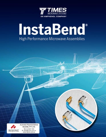
InstaBend
High Performance Microwave Assemblies
Index
PAGE:
InstaBend® 047
InstaBend® 086
InstaBend® 141 6 4 8
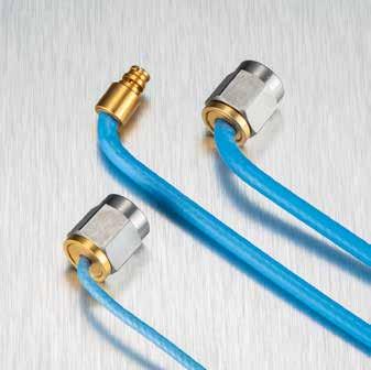
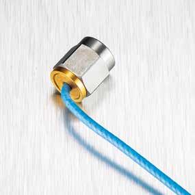
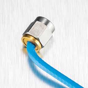
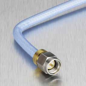
InstaBend® microwave cable assemblies are flexible, high-performance solutions designed to connect RF circuit cards, modules, and enclosure panels. Built to perform over a wide operating frequency range and with connectors designed to support lowprofile bends, InstaBend simplifies cable routing for applications with space constraints. Readily available in a variety of lengths and connector types, InstaBend is the versatile choice for a wide range of applications.
Applications:
• Cellular base stations
• Radar systems
• Satellite communications
• Medical imaging
• Test and measurement equipment
Higher performance stability
Great connector retention (≥25 lbs)
No center conductor deformation when bent
Ready for harsh environment
Excellent durability
Cable Assembly Comparison Chart
CableMax.FrequencyCable DiameterFlexure Loss Power Handling TemperatureRange
InstaBend® 047 50 GHz 0.061 in (1.55 mm)
InstaBend® 086 50 GHz 0.105 in (2.67 mm)
InstaBend® 141 32 GHz 0.163 in (4.14 mm)
Cable Assembly Guide
Selecting the correct assembly for the right application is not always an easy task. Below are some considerations when selecting High Performance Microwave Assemblies.
800-867-2629 2 3 www.timesmicrowave.com
Frequency (GHz) InstaBend
InstaBend® 086 InstaBend® 047 0 Higher Small Lower Large 18 50 32 LOSS CABLE DIAMETER
® 141
Rev. 4 : 06/2023
CABLE-CONNECTOR OPTIMIZATION
GROUND-UP RUGGEDIZATION
InstaBend® 047
High Performance Microwave Assemblies
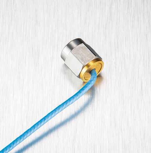
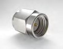
InstaBend® 047 are flexible coaxial microwave assemblies designed for interconnects between RF circuit cards, medical equipment, and enclosure panels. This cable's low profile and flexure allows for bending close behind the connector which simplifies cable routing. IB-047 assemblies are available in a variety of lengths and connector types, making them a versatile solution for a wide range of applications.
Features:
• Readily Available
• Low-profile bending close to the connector back-end for minimal footprint
• Lightweight
Specifications
K1
K2
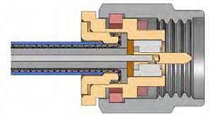
CENTER CONDUCTOR
Silver Plated Copper
DIELECTRIC PTFE
SHIELD
Silver Plated Copper Clad Steel
OUTER BRAID
Silver Plated Copper Clad Steel
JACKET
Blue FEP
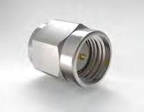
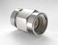
800-867-2629 45 www.timesmicrowave.com ConnectorsCodePart-Number Stock Code Description VSWR max KM IB-047-KM 47425 2.92 mm, male, straight 1.35 @ DC-12.4 GHz 1.50 @ 12.4- 18 GHz SM IB-047-SM 47396 SMA, male, straight 1.20 @ DC-6.0 GHz 1.35 @ 6.0-26.5 GHz SMPF IB-047-SMPF 47432 SMP, female, straight 1.20 @ DC-6.0 GHz 1.35 @ 6.0-26.5 GHz 1.40 @ 26.5-40.0 GHz
dB/ft dB/m
0.011950.03920795
0.0000130.000042653 Calculation IL = (K1 x √(f) + K2 x f) x Cable Length + Connector Loss Cable Insertion Loss f = Frequency (MHz) Typical Connector Loss K values Use K values with matching length unit Units Diameter in (mm)0.061 (1.55) Weight lb/ft (g/m)0.004 (6.0) Minimum Bend Radius in (mm)0.130 (3.30)
Frequency GHz50 Maximum Operating Voltage VACrms 100 Capacitance pF/ft (pF/m)29.9 (98.1) Delay ns/ft (ns/m)1.45 (4.76) Shielding dBc -90
Maximum
Op Temp -85 to 257ºF -65 to 125ºC Impedance 50 Ohms Frequency (MHz) dB/pr Frequency (MHz) dB/pr 500 0.04 10000 0.19 1000 0.06 12000 0.21 2000 0.08 14000 0.22 4000 0.12 16000 0.24 6000 0.15 18000 0.25 8000 0.17 Ordering Guide IB047 -XX XX- XX.X XX - Connector A Connector B - Length in / ft / cm / m
Features:
• Readily available
• Extreme bending from the back of the connector for minimal footprint
• 90º torque resistance
• Highly stable VSWR
• Ruggedized backend
DIELECTRIC PTFE
CENTER CONDUCTOR
Silver Plated Copper Clad Steel SHIELD
Silver Plated Copper Braid
INTERLAYER Metalized Polyester Tape
Ordering Guide
K2
JACKET
Blue FEP
OUTER BRAID
Silver Plated Copper Clad Steel
800-867-2629 67 www.timesmicrowave.com
dB/ft
dB/m K1 0.0064460.021148
= (K1 x √(f) + K2 x f) x Cable Length + Connector Loss Cable Insertion Loss f = Frequency (MHz) Typical Connector Loss K values Use K values with matching length unit Units Diameter in (mm)0.105
lb/ft (g/m)0.013
Bend Radius in (mm)0.25
Frequency
Maximum Operating Voltage VACrms 100 Velocity of Propagation % 70 Capacitance pF/ft (pF/m)29
ns/ft (ns/m)1.45
dB>90
Op Temp -85 to 257ºF -65 to 125ºC Impedance 50 Ohms
0.0000130.000043 Calculation IL
(2.67) Weight
(19.3) Minimum
(6.35) Maximum
GHz50
(95.1) Delay
(4.76) Shielding
Specifications
Frequency (MHz) dB/pr Frequency (MHz) dB/pr 500 0.04 10000 0.19 1000 0.06 12000 0.21 2000 0.08 14000 0.22 4000 0.12 16000 0.24 6000 0.15 18000 0.25 8000 0.17 IB086 -XX XX- XX.X XX - Connector A Connector B - Length in / ft / cm / m InstaBend® 086
Performance Microwave
High
Assemblies
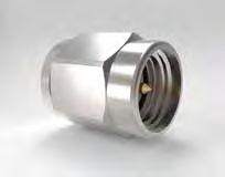
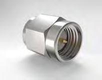
InstaBend®086 are flexible coaxial microwave assemblies designed for interconnects between RF circuit cards, modules, and enclosure panels. This cable is an optimal compromise between flexure, loss, and power handling. ConnectorsCodePart-Number Stock Code Description VSWR max KM IB-086-KM 47393 2.92 mm, male, straight 1.25 @ DC-27 GHz 1.40 @ 27-40 GHz SM IB-086-SM 47388 SMA, male, straight1.25 @ DC-27 GHz SMPF IB-086-SMPF 47389 SMP, female, straight 1.35 @ DC-12.4 GHz 1.50 @ 12.4- 18 GHz 1.70 @ 18- 40 GHz
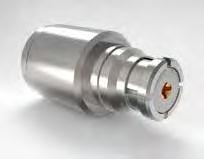
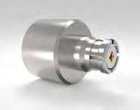
InstaBend®141 is a flexible, coaxial microwave assembly designed for interconnects between RF circuit cards, modules, and enclosure panels. This cable is best for applications requiring low loss and power handling.
Features:
• Readily available
• Low-profile bending for minimal footprint
• Weight savings vs. semi-rigid
• Highly ruggedized
Specifications
DIELECTRIC Extruded PTFE
CENTER CONDUCTOR
Silver Plated Copper SHIELD
Silver Plated CopperBraid
INTERLAYER Metalized Polyester Tape
OUTER BRAID
Silver Plated Copper Clad Steel Braid
JACKET
Blue FEP
Shielding dB>90
K1 0.0036260.011897
K2 0.0000130.000043
800-867-2629 89 www.timesmicrowave.com
dB/ft dB/m
IL = (K1 x √(f) + K2 x f) x Cable Length + Connector Loss Cable Insertion Loss f = Frequency (MHz) Typical Connector Loss K values Use K values with matching length unit Units Diameter in (mm)0.163 (4.14) Weight lb/ft (g/m)0.028 (41.7) Minimum Bend Radius in (mm)0.5 (12.7) Maximum Frequency GHz 27 Maximum Operating Voltage VACrms250 Velocity of Propagation % 70 Capacitance pF/ft (pF/m)29.3 (98.1)
ns/ft (ns/m)1.45 (4.77)
Calculation
Delay
Op Temp -85 to 257ºF -65 to 125ºC Impedance 50 Ohms
Frequency (MHz) dB/pr Frequency (MHz) dB/pr 500 0.04 10000 0.19 1000 0.06 12000 0.21 2000 0.08 14000 0.22 4000 0.12 16000 0.24 6000 0.15 18000 0.25 8000 0.17
XX- XX.X XX - Connector
Connector B
Length in / ft / cm / m
Performance
ConnectorsCodePart-Number Stock Code Description VSWR max SM IB-141-KM 47426 SMA, male, straight 1.2 @ DC - 12 GHz 1.3 @ 12 - 27 GHz
Ordering Guide IB141 -XX
A
-
InstaBend® 141 High
Microwave Assemblies

Times Microwave Systems 358 Hall Avenue Wallingford, CT 06492 USA T 800. 867.2629