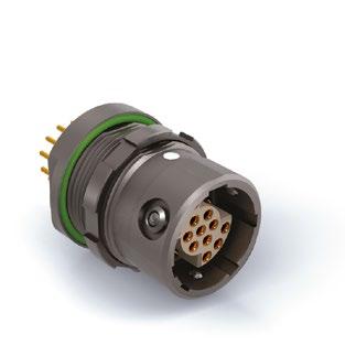
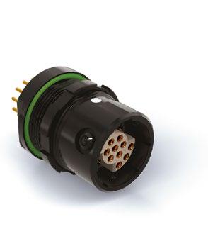
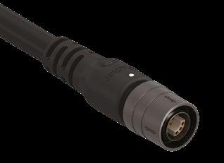
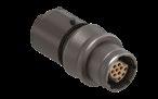
J FISCHER
RECEPTACLES
■ Unique combinations of signal and power
■ Replace multiple large connectors with fewer and smaller ones
■ Combine multiple protocols into one connector
UP TO 45% SMALLER
SIZE 08
COMPARED TO STANDARD RECEPTACLES WITH SIMILAR NUMBER OF CONTACTS
UP TO 75% LIGHTER
SIZE 08
Competitor O
Competitor L
11
dimensions and images shown are in millimeters and are for reference only.
PLUGS & RECEPTACLES WEIGHT COMPARISON WITH SIMILAR NUMBER OF CONTACTS
UltiMate 11/13
MiniMax 08
Receptacle Plug
HIGH-SPEED DATA TRANSFER
USB 2.0
USB 3.2 GEN 1 (5 Gbit/s)
USB 3.2 GEN 2 (10 Gbit/s)
ETHERNET (10 Gbit/s)
Standard audio/ video protocol (10.2 Gbit/s)
Standard audio/ video protocol (18.0 Gbit/s)
Single pair
Ethernet (1 Gbit/s)
* Application dependent
Note that for USB 3.2 the full spec is set with 1 m cable
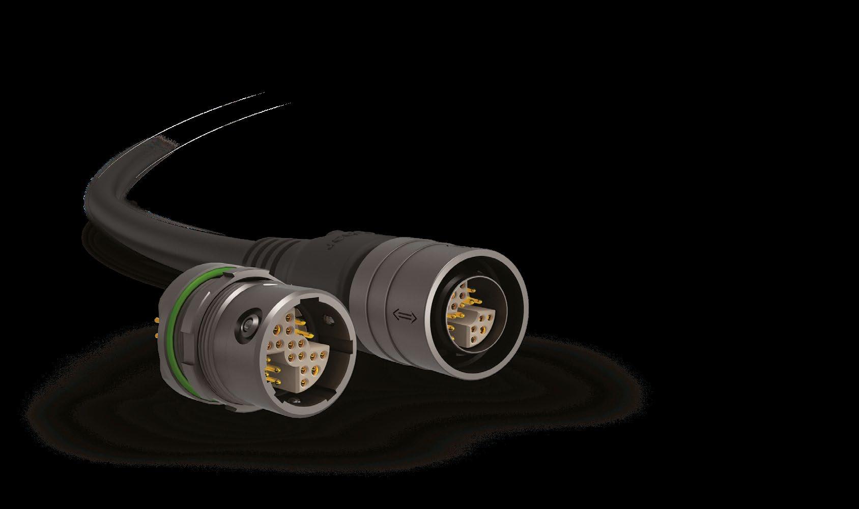
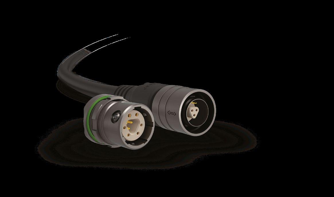
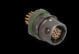
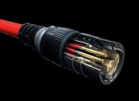
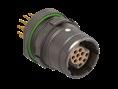
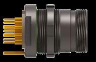
ETHERNET SIZE 08 | 8 PINS
A unique robust and sealed miniature connector for Ethernet applications in harsh environments.
■ AWG24, compatible with long range standard Ethernet cables
■ Symmetrical hermaphroditic contact block
■ 0.5 mm contacts
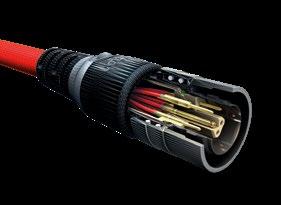
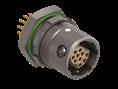
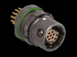
USB 3.2 SIZE 08 | 9 PINS + SIZE
Optimized design for full USB 3.2 Gen 1 and Gen 2 performance, successfully tested to the full S-parameter standards with cables up to 1 m.
■ Advanced power contacts
■ Hermaphroditic contact block
■ 0.5 mm contacts
RELIABILITY
■ IP68, -20m/24h* water sealing <10-6 mbar l/s gas sealing
■ 5,000 mating cycles
■ 1,000 h salt mist spray
*The standard sealing level can be achieved on all MiniMax panel mounted receptacles when correctly integrated.
For all cabled mounted connectors, the sealing level depends on the quality of the assembly process and the size and type of cable being used. For MiniMax, Fischer Connectors guarantees an IP64 cable assembly sealing as standard. Upon request, MiniMax cable assemblies with an IP68 sealing rating -20 m for a duration of 24 hours are available and might require additional testing.
HOUSING COLORS
MiniMax is available in two housing colors: ANTHRACITE Nickel and BLACK Chrome 1)
■ Both color solutions are non-reflective and offer a discreet connector solution for military applications.
■ The anthracite treatment offers an improved panel grounding of <5 mΩ as required by MIL specs.
Ground contact connected to housing:
- Pin for PCB contact (P) versions
- Solder barrel for solder contact (S) versions
CONTACT COMBINATIONS
The MiniMax contact block is specified by a combination of 4 digits:
- First digit indicates the number of advanced contacts for first mate / last break.
- Second digit indicates the number of larger contacts (and with larger solder cup) for power.
- Digits 3 and 4 are to be considered as one number and will indicate the number of remaining contacts (of standard size and not advanced).
MiniMax uses a hermaphroditic contact block for all configurations except for the 4-pin (2 power + 2 signal) and the 7-pin (3 power + 4 signal) in size 06.
For the 4-pin and 7-pin in size 06, a polarity choice2) has to be specified and the mating part will reflect an opposite polarity (F mating M; M mating F).
For clarity reasons, the 4-pin in size 06 with 2 power contacts that are also advanced is designated by the digits 0202 and not 2202. A designation by the digits 2202 may confusingly suggest it has 6 contacts instead of the actual 4.
The table on the right shows all available standard contact block combinations to help specify the correct product designation. (Also see page J-20).
1) MR12 body style not available in BLACK. Please contact your local sales representative.
2) Size 06 7-pin configuration is receptacle with female contacts and plug with male contacts. For customization please contact your local sales representative.
Body styles
PLUGS
Body style
Protection
Locking system
Sealed up to IP68
Hermetic
Push-pull
Quick-release
Screw
Termination Crimp contact
References to detailed information
Sealing categories, page A-6
Electrical & contact configurations, page J-16 Solder contact
Housing color ANTHRACITE Nickel
Part numbering, page J -20 BLACK Chrome
Shortened body
60° angle 1)
Design
Straight Right-angle 1)
Cabling
Body styles, chapter J
Cable clamp sets - Overmoldable
Heat shrinkable
Cable bend reliefs 1)
Accessories
Protective sleeves
Sealing caps
Size
1) Not available for size 10.
All dimensions and images shown are in millimeters and are for reference only.
Accessories, page J-21 and J-22
Technical dimensions, page J-8 and J-9 For more information visit our website www.fischerconnectors.com/technical
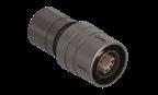
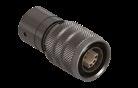
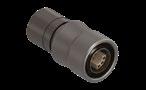
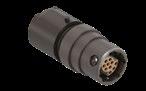
PLUGS
MP11-L / PUSH-PULL
BODY STYLE
MP11-S / SCREW-LOCKING
BODY
MP11-Q / QUICK-RELEASE
BODY STYLE
DIMENSIONS OF OVERMOLDING 1)
MP11-L/S/Q – MR50-L/S/Q STRAIGHT OVERMOLDING
1) Overmolding available on request. Contact your Fischer Connectors sales representative for details.
dimensions and images shown are in millimeters and are for reference only.
White Dot (keying orientation) (View from B) 8 POSITIONS ORIENTATION
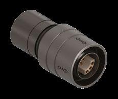
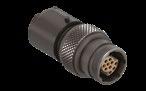
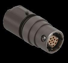
RECEPTACLES
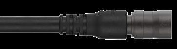
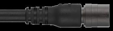
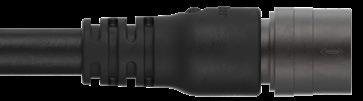
CABLE MOUNTED
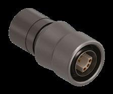
MR50-L / PUSH-PULL BODY STYLE
MR50-S / SCREW-LOCKING BODY STYLE
All dimensions and images shown are in millimeters and are for reference only.
MR50-Q / QUICK-RELEASE BODY STYLE
RECEPTACLES
Body style
Protection
Termination
Sealed up to IP68
Hermetic
References to detailed information
Sealing categories, page A-6
Crimp contact Electrical & contact configurations, page J-16
page J -20
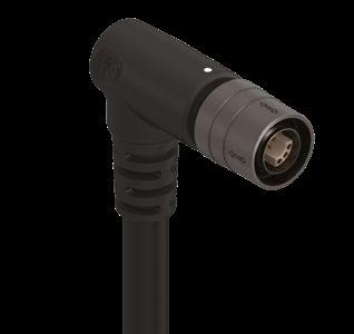
Design Right-angle Body styles, chapter J Flush
Assembly
Accessories
Front-projecting
Bulkhead feedthrough
Front-mounting
Rear-mounting
Sealing caps
Spacers
Color-coded washers
Grounding washers
Locking washers
Accessories, page J-21 and J-22
page J-13 to J-15 For more information visit our website
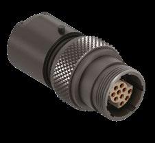
RECEPTACLES
PANEL REAR MOUNTED
MR11-L / PUSH-PULL BODY STYLE
MR12-L
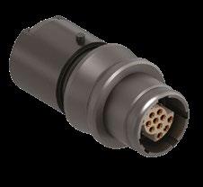
RECEPTACLES
PANEL REAR MOUNTED
MR11-Q / QUICK-RELEASE BODY STYLE
MR12-Q / QUICK-RELEASE BODY STYLE
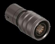
RECEPTACLES
MR11-S / SCREW-LOCKING
1) Stranding values in brackets.
2) Current per contact at 40 °C temperature rise measured on the basic curve according to IEC 60512-5-2-5b. For the max. operating current a reduction factor must be used and limitations due to the size of the wires and the permissible upper temperature limit of the materials employed must be taken into account. See page A-12 for details.
3) Recommended operating voltage at sea level. This rated voltage is a general guideline where no other electrical safety standard applies. In
cases where other standards rule a specific use of the connector, the application-specific safety criteria shall be considered first. This must be evaluated in the framework of equipment engineering.
4) Two advanced signal contacts for USB power are available for Solder (S) or PCB (P) receptacles.
5) USB 3.2 contact blocks come with two advanced power contacts on the plug side (MP11) as standard (size 08 plug 9-pin contact block 2007 and size 10 plug 12-pin contact block 2307).
6) Test voltage between contacts 0.9 and contacts 0.5 for configuration
MiniMax size 10 2307/0309.
7) Test voltage between contacts 0.7 and contacts 0.5 for configuration
MiniMax size 06 0304.
8) Contacts 0.7mm suitable for SPE data protocol 1 Gbit/s.
9) Layout dedicated to 4K UHD Audio / Video Protocol 18.0 Gbit/s.
10) Current of 1.4 A at a maximum temperature rise of 30 °C according to UHD specifications.
MECHANICAL AND VISUAL CODING
The mechanical coding for MiniMax is available as standard in 4 different variants : code 1, 2, 3, 4.
When size, body type, configuration and code matches the plug and receptacle will mate by aligning the exterior white marks (coding guide).
For additional differentiation, the odd codes are visually identified by a beige contact block while the even codes will vary with a black insulator.
06
3
4
All dimensions and images shown are in millimeters and are for reference only.
Visual coding
08
1 Code 2
4 Visual coding
4
Visual coding
PCB hole layout and recommended wiring
Ground contact connected to housing:
- Pin for PCB contact (P) versions - Solder barrel for solder contact (S) versions
Recommended wiring
1) Recommended 2) Optional on MR11 / MR12
1/6; 3/10; 7/8; 11/12 1) 1/2; 3/4; 5/6; 7/8 1) 8/19; 10/11; 13/14; 16/17 1) 15/16; 18/19; 21/22; 13/24 1) Any other 1)
08, configuration 9 contacts
USB Signal name 3) 3) RX/TX labelling of Fischer Rugged Flash Drive. The RX of one device must always connect to the TX of the other device and vice versa.
UHD 18.0 Gbit/s protocol
Size 08, configuration 19 contacts
DDC/CEC Ground 3) Utility 4) Hot plug detect 5) SDA 6) SCL 7) CEC (delayed contact) 8) TMDS data 29) TMDS data 1 shield
10) TMDS data 1+
Size 10, configuration 12 contacts
11) TMDS data 112) TMDS data 0 shield 13) TMDS data 0+ 14) TMDS data 015) TMDS data CLK shield
16) TMDS data CLK + 17) TMDS data CLK18) TMDS data 2 shield 19) TMDS data 2+
View from the back of the plug/front of receptacle (guide mark at 12 o’clock)
All contacts are male or female depending on polarity.
Contacts
Plugs Receptacles
Male Female
Female Male
dimensions and images shown are in millimeters and are for reference only.
View from the back of the plug/front of receptacle (guide mark at 12 o’clock)
Plugs Receptacles
Male Female
View from the back of the plug/front of receptacle (guide mark at 12 o’clock)
Contacts Plugs Receptacles
dimensions and images shown are in millimeters and are for reference only.
PLUGS & RECEPTACLES
Body style
MiniMax plug = MP
■ MP11 = Cable mounted
MiniMax receptacle = MR
■ MR11 = Panel mounted
■ MR12 = Panel mounted
■ MR50 = Cable mounted
Sealing level
MP11, MR50
■ Z = not applicable
Locking system
MiniMax plug & receptacle
■ L = Push-pull locking
■ S = Screw-locking
■ Q = Quick-release
MR11, MR12
■ W = water sealing (IP68)
Connector size
■ 06 = Size 6
■ 08 = Size 8
■ 10 = Size 10
Number of contacts (see page J-6)
■ Digit 1 = Advanced contacts (if applicable)
■ Digit 2 = Power contacts (where physically larger than the other contacts)
■ Digit 3+4 = Remaining contacts
1) MR12 body style not available in Black (BK). Please contact your local sales representative.
2) Configuration 0304 is standard with F for receptacle and M for plug. For customization please contact your local sales representative.
Termination
MP11, MR50
■ S = Solder contact MR11, MR12
■ P = PCB contact
■ S = Solder contact
Contact bloc
■ A = Hermaphroditic (both MR and MP need to be “A”)
■ F* = Female contacts
■ M* = Male contacts
* only for size 06 configuration 0202 and 0304 2) (if MR = “F” then MP = “M”; if MR = “M” then MP = “F”)
Insulating material
■ 1 = PEEK
Interface O-ring material
MP11
■ Z = Not applicable
Keying code
MR11, MR12, MR50
■ E = EPDM
■ 1 = Code 1 (insulator= Beige)
■ 2 = Code 2 (insulator= Black)
■ 3 = Code 3 (insulator= Beige)
■ 4 = Code 4 (insulator= Black)
Housing color
■ AN = Anthracite
■ BK = Black 1)
All dimensions and images shown are in millimeters and are for reference only.
To avoid getting debris into the caps when the connectors are mated, please mate the caps together. Please make sure that the cap is in place when the plug or the receptacle is in unmated position.
STRAIGHT BEND RELIEF
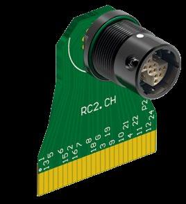
PC-BOARD TERMINATION
■ Rigid flex solution available for SMD connectors
■ Compatible with signal & power
■ Available for 19 & 24 pin configuration.1)
CUTTING DIAMETERS
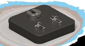
Assembled Rigid Flex with MR11 receptacle push-pull size 08 24 pins with PCB terminations, black, code 1
1) Custom design and other configurations available upon request. Contact your Fischer Connectors sales representative.
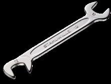
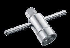
SPANNER & NUT DRIVER
NUT DRIVER WITH T-HANDLE AND HEX DRIVE
Material – Hardened Tool Steel, Nickel plated.
SINGLE SIDED HEX NUT DRIVER
Material – Hardened Tool Steel, Nickel plated and plastic.
Material – Chrome Alloy Steel, Chrome plated, Fork Angles – 15° and 75°.
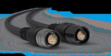
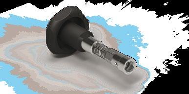
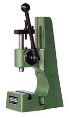
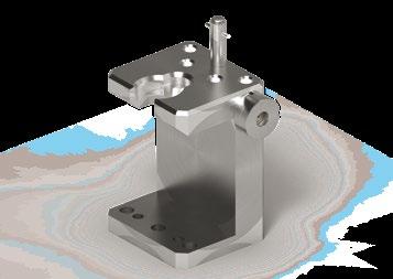
CABLE ASSEMBLY
Note: Cable assembly is only possible with special tooling developed by Fischer Connectors. Due to the complexity of the connector purchase costs may be significant. As an alternative solution, Fischer Connectors offers premium cable assembly services.
dimensions and images shown are in millimeters and are for reference only.
MATERIAL & SURFACE FINISH
Metal components
Housing, Nut Brass CuZn39Pb3
Back nut (MP11, MR50)
Brass CuZn39Pb3
Ground contact Brass CuZn39Pb3
Push-pull locking spring
CW614N UNS C 38500
CW614N UNS C 38500
CW614N UNS C 38500
Quick-release locking spring Stainless steel X10CrNi18-8 (1.4310)
Contacts
- Male, Ground Pin - Female Brass CuZn39Pb3 Bronze CuSn4Zn4Pb4
Ball-locking Ceramic Si3N4
CW614N; UNS C 38500
CW456K; ASTM B139 UNS C 54400
Insulator and sealing International symbol Flammability
Insulators PEEK1) UL 94 V-0
O-rings - General - Interface FPM (Viton®) EPDM
Sealant - Cable connectors - Panel receptacles Epoxy compound Silicone/Epoxy2) compound
UL 94 V-0
Bend relief - Cable connectors SantopreneTM TPV 101-73 UL 94 HB
Cap - Cable connectors - Panel receptacles TPV (SantopreneTM ) UL 94 HB
1) Or any material in the PAEK family that provides equal or better overall performances.
2) For panel receptacle size 10.
Chrome over Nickel Anthracite Nickel
SAE-AMS2460
SAE-AMS2404
SAE-AMS-QQ-N-290
SAE-AMS-QQ-N-290B SAE-AMS2404G
MIL-DTL-45204D Type I; ASTM B488
MIL-DTL-45204D Type I; ASTM B488
ENVIRONMENTAL & MECHANICAL DATA
Characteristic Performance Standard
Sealing performance mated and unmated
Sealing performance Soft Cap
IP68, -20m/24h water sealing <10-6 mbar l/s gas sealing
IP67; 15 cm submersion for 30 min
Operating temperature range 1) -40 °C to +135 °C
Corrosion resistance mated Salt mist 1,000 hours ; 5% salt solution, 35 °C
Plug and receptacle in mated position or with cap when unmated.
Appearance may change over time without impacting mechanical or electrical functions.
5,000 mating cycles
Endurance
Vibration
Screw-locking version only
Vibration
Push-pull version
Unlocking Force
Quick-release version only
Preserved mechanical and electrical functionality. Normal wear will appear.
10 to 2,000 Hz, 1.5 mm or 15 g, 12 sweep cycles per axis, 20 minutes per 10-2,000-10 Hz sweep cycle, no discontinuity >1 μs, no visible signs of damage
10 to 500 Hz, (1.5 mm or 10 g, 12 sweep cycles per axis, 15 minutes per 10-500-10 Hz sweep cycle, no discontinuity >1 μs, no visible signs of damage
Size 06 = Typical 25 N±40%
Size 08 = Typical 35 N±40%
Size 10 = Typical 60 N±40%
Shock 300 g
1) Max temperature of +85 °C for soft caps.
ELECTRICAL DATA
Characteristic
Contact resistance 5 mΩ (typical value) IEC 60512-2-1-2a; IEC 60512-2-2-2b
Shell resistance 2) ANTHRACITE <5 mΩ (Cabled) IEC 60512-2-6-2f BLACK <50 mΩ (Cabled) IEC 60512-2-6-2f
Insulation resistance >1010 Ω IEC 60512-3-1-3a
Shielding effectiveness 360° shielded -
2) Measured for a mated pair of panel receptacle and cable plug between the grounding pin and the cable shielding.
All dimensions and images shown are in millimeters and are for reference only.
IEC 60529
IEC 60068-2-17 Test Qk, Method 3
IEC 60529
IEC 60512-6-1
IEC 60068-2-14-Nb
IEC 60068-2-11 Test Ka; MIL-STD-202 Method 101; EIA-364-26
IEC 60512-9-1
MIL-STD-202 Method 204 Condition B
MIL-STD-202 Method 204 Condition A
MIL-STD-202 Method 213; EIA-364-27