Fischer Connectors Ultimate Series Technical Catalogue

Page 1


CHAPTER

FISCHER ULTIMATETM SERIES

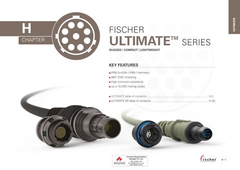
RUGGED | COMPACT | LIGHTWEIGHT

KEY FEATURES

■ IP68 2m/24h / IP69 / Hermetic

■ 360° EMC shielding

■ High corrosion resistance

■ Up to 10,000 mating cycles

■ ULTIMATE table of contents

■ ULTIMATE 80 table of contents

H- 2 / H- 32

PLUGS

ULTIMATE

CABLE MOUNTED

RECEPTACLES

FOR ALL ULTIMATE

For specific requests, including hybrid or custom connectors, please contact your local sales representative.

AVAILABLE SIZES

CONNECTOR SIZE VERSUS CABLE DIAMETER

PLUGS

Body style

Protection Sealed up to IP68

References to detailed information

Sealing categories, page A-6 Hermetic

Locking system Friction

Locking systems, page A-5 Push-pull Quick-release Lanyard

Tamperproof

Crimp contact

Termination

Electrical & contact configurations, pages H-13 to H-18 Solder contact

Housing material Brass

Part numbering, page H-26 Aluminum

Housing material Anthracite

Part numbering, page H-26 Black

Shortened body

Design

Body styles, chapter H Straight Right-angle

Cabling Cable clamp sets

Overmoldable

Heat shrinkable

Accessories Cable bend reliefs

Accessories, page H-27 Protective

Technical dimensions, page H-5 For

CABLE MOUNTED UP01 BODY STYLE PLUGS

PLUGS

Body style

Protection Sealed up to IP68

References to detailed information

Sealing categories, page A-6 Hermetic

Locking system Friction

Push-pull Quick-release

Lanyard

Tamperproof

Crimp contact

Termination

Locking systems, page A-5

Electrical & contact configurations, pages H-13 and H-15 Solder contact

Housing material Brass

Part numbering, page H-26 Aluminum

Housing color Anthracite

Part numbering, page H-26 Black

Shortened body

Design

Body styles, chapter H Straight Right-angle

Assembly Front-mounting

Rear-mounting

Accessories Cable bend reliefs

Accessories, page H-27 Protective sleeves

Sealing caps

Size 07

Technical dimensions, page H-7 For more information visit our website www.fischerconnectors.com/technical 11

PANEL FRONT MOUNTED

BODY STYLE PLUGS

dimensions and images shown are

Body

Protection Sealed up to IP68

References

Sealing categories, page A-6 Hermetic

Termination Crimp contact

Electrical & contact configurations, pages H-13 to H-16 Solder contact

Housing material Brass

Part numbering, page H-26 Aluminum

Housing color Anthracite

Part numbering, page H-26 Black

Design Shortened body

Body styles, chapter H Straight Right-angle

Cabling Cable clamp sets Overmoldable

Accessories

Accessories, page H-27

Technical dimensions, page H-9

For more information visit our website

RECEPTACLES

All dimensions and images shown are in millimeters and are for reference only. Technical dimensions CABLE MOUNTED UR50 BODY STYLE

Body

Protection

Termination

Housing material

Housing color

Sealed up to IP68

Hermetic

Crimp contact

Solder contact

PCB contact

Brass

Aluminum

Anthracite

Black

Right-angle

Flush

Design

Assembly

Accessories

Front-projecting

Bulkhead feedthrough

Front-mounting

Rear-mounting

Sealing caps

Spacers

Color-coded washers

Grounding washers

Locking washers

References to detailed information

Sealing categories, page A-6

Electrical & contact configurations, page H-13 to H-18

Part numbering, page H-26

Part numbering, page H-26

Body styles, chapter H

Accessories, page H-27

Technical dimensions, page H-11 and H-12

For more information visit our website www.fischerconnectors.com/technical

RECEPTACLES

PANEL REAR MOUNTED*

UR01

BODY STYLE

* Standard version with PCB contacts and grounding pin. For solder contact version, a special solder ground contact pin is included for AWG22[7/30].

1) Solder & PCB ground pins are always equal or larger than the largest contact of corresponding contact bloc layout (except size 13 config. 203 AWG12 [7/20] )

2) 3.6 mm for size 15

dimensions and images shown are

RECEPTACLES

PANEL FRONT MOUNTED* UR03

BODY STYLE

* Standard version with solder contacts.

Electrical & contact configurations

1) Stranding values are in brackets.

2) See dedicated crimping instructions document for further information.

3) For a given AWG, the diameter of some stranded cable designs could be larger than the hole diameter of the barrel. Testing may be required.

4) Current per contact at 40 °C temperature rise measured on the basic curve according to IEC 60512-5-2-5b. For maximum operating current, a reduction factor must be used and limitations due to the size of the wires and the permissible upper temperature limit of the materials employed must be taken into account. See page A-12 for details.

5) Recommended operating voltage at sea level. This rated voltage is a general guideline where no other electrical safety standard applies. In cases where other standards rule a specific use of the connector, the application-specific safety criteria shall be considered first. This must be evaluated in the framework of equipment engineering.

6) Standard polarity only.

7) Layout dedicated to SPE data protocol 1 Gbit/s

1) Stranding values are in brackets.

2) See dedicated crimping instructions document for further information.

3) For a given AWG, the diameter of some stranded cable designs could be larger than the hole diameter of the barrel. Testing may be required.

4) Current per contact at 40 °C temperature rise measured on the basic curve according to IEC 60512-5-2-5b. For maximum operating current, a reduction factor must be used and limitations due to the size of the wires and the permissible upper temperature limit of the materials employed must be taken into account. See page A-12 for details.

5) Recommended operating voltage at sea level. This rated voltage is a general guideline where no other electrical safety standard applies. In cases where other standards rule a specific use of the connector, the application-specific safety criteria shall be considered first. This must be evaluated in the framework of equipment engineering.

Electrical & contact configurations

1) Stranding values are in brackets.

2) See dedicated wire gauge crimping instructions document for further information.

3) For a given AWG, the diameter of some stranded cable designs could be larger than the hole diameter of the barrel. Testing may be required.

4) Current per contact at 40 °C temperature rise measured on the basic curve according to IEC 60512-5-2-5b. For maximum operating current, a reduction factor must be used and limitations due to the size of the wires and the permissible upper temperature limit of the materials employed must be taken into account. See page A-12 for details.

5) Recommended operating voltage at sea level. This rated voltage is a general guideline where no other electrical safety standard applies. In cases where other standards rule a specific use of the connector, the application-specific safety criteria shall be considered first. This must be evaluated in the framework of equipment engineering.

6) Not valid for UP50.

7) UR0x: standard polarity only.

1) Stranding values are in brackets.

2) See dedicated wire gauge crimping instructions document for further information.

3) For a given AWG, the diameter of some stranded conductor designs could exceptionally be larger than the hole diameter of the barrel. Testing may be required.

4) Current per contact at 40 °C temperature rise measured on the basic curve according to IEC 60512-5-2-5b. For the max. operating current a reduction factor must be used and limitations due to the size of the wires and the permissible upper temperature limit of the materials employed must be taken into account. See page A-12 for details.

5) Recommended operating voltage at sea level. This rated voltage is a general purpose guideline where no other electrical safety standard applies. In cases where other standards rule a specific use of the connector, the application-specific safety criteria shall be considered first. This must be evaluated in the framework of equipment engineering.

6) UR0x: standard polarity only.

7) Only valid for UP01.

8) Contact block with male contacts comes standard with advanced power contacts.

9) UR0x: only available in "V" (Vacuum sealing) version, not in "W" (Water sealing) nor in "N" (Non sealing) versions.

Electrical & contact configurations

1) Stranding values are in brackets.

2) For a given AWG, the diameter of some stranded conductor designs could exceptionally be larger than the hole diameter of the barrel. Testing may be required.

3) Current per contact at 40 °C temperature rise measured on the basic curve according to IEC 60512-5-2-5b. For the max. operating current a reduction factor must be used and limitations due to the size of the wires and the permissible upper temperature limit of the materials employed must be taken into account. See page A-12 for details.

4) Recommended operating voltage at sea level. This rated voltage is a general purpose guideline where no other electrical safety standard applies. In cases where other standards rule a specific use of the connector, the application-specific safety criteria shall be considered first. This must be evaluated in the framework of equipment engineering.

5) Standard polarity only.

6) Contacts dia. 1.6 are positioned to make contact first and break last.

7) Please refer to www.fischerconnectors.com/technical for technical specification of coax insert.

8) Max 500 mating cycles due to coax insert characteristics.

9) UR0x: only available in "V" (Vacuum sealing) version, not in "W" (Water sealing) nor in "N" (Non sealing) versions.

1) Stranding values are in brackets.

2) See dedicated wire gauge crimping instructions document for further information.

3) For a given AWG, the diameter of some stranded cable designs could be larger than the hole diameter of the barrel. Testing may be required.

4) Current per contact at 40 °C temperature rise measured on the basic curve according to IEC 60512-5-2-5b. For maximum operating current, a reduction factor must be used and limitations due to the size of the wires and the permissible upper temperature limit of the materials employed must be taken into account. See page A-12 for details.

5) Recommended operating voltage at sea level. This rated voltage is a general guideline where no other electrical safety standard applies. In cases where other standards rule a specific use of the connector, the application-specific safety criteria shall be considered first. This must be evaluated in the framework of equipment engineering.

6) Standard polarity only.

MECHANICAL CODING

POLARITY

BODY STYLES

POLARITY

Standard polarity: male contacts on plug / female contacts on receptacle

Inverted polarity: female contacts on plug / male contacts on receptacle.

WARNING: for high-current applications, make sure to choose the correct polarity (female contacts on device that is supplying the power).

PCB / PIN LAYOUT

1) Recommended PCB hole dimensions may be adjusted to application.

a) For optional ground pin.

View from F 1)

Technical dimensions

PCB / PIN LAYOUT

View from F 1)

1) Recommended PCB hole dimensions may be adjusted to application.

a) For optional ground pin.

All dimensions and images shown are in millimeters and are for reference only.

PCB / PIN LAYOUT

View from F 1)

1) Recommended PCB hole dimensions may be adjusted to application.

a) For optional ground pin.

1) Recommended PCB hole dimensions may be adjusted to application.

a) For optional ground pin.

All dimensions and images shown are in millimeters and are for reference only.

PCB / PIN LAYOUT

View from F 1) 2)

1) Recommended PCB hole dimensions may be adjusted to application.

2) N/A for pin layout 204H.

a) For optional ground pin.

PCB / PIN LAYOUT

View from F 1)

1) Recommended PCB hole dimensions may be adjusted to application.

a) For optional ground pin.

All dimensions and images shown are in millimeters and are for reference only.

PLUGS & RECEPTACLES

Housing Material

■ A = ALUMINUM ■ B = BRASS (Standard)

Grounding

Panel mounted :

Cable mounted :

UltiMate Plug = UP

■ UP01 = Cable mounted

■ UP50 = Panel mounted

UltiMate Receptacle = UR

■ UR01 = Panel rear mounted low profile

■ UR02 = Panel rear mounted

■ UR03 = Panel front mounted low profile

■ UR50 = Cable mounted

Panel mounted :

■ V = Vacuum sealing 1)

■ W (IP68/69) = Water sealing

■ N = Non sealing 2)

Cable mounted :

■ Not applicable = Nothing Sealing level Body style

Locking system

Cable mounted plug :

■ L = Push-pull locking

■ Q = Quick release

Cable mounted receptacle :

■ Z = Not applicable

Panel mounted :

■ No locking = Nothing

Connector size

■ 07 = Size 07

■ 08 = Size 08

■ 11 = Size 11

■ A = Grounding pin (for UR01/UR02)

■ Z = Not applicable

■ N = None (for UR03/UP50)

Insulator Material

■ 1 = PBT. Size 08/11/13/18 ■ 2 = PEEK. Size 07/15

O-ring material

Receptacle : O-ring at plug interface

■ E = FVMQ (Fluorosilicone)

Keying code

■ Code 1 =

■ Code 2 = Standard keying = Code 1

Housing color

■ BK = Standard (Anthracite)

Contact Type

■ S = Solder

■ P = PCB

Layout references

■ Size 07 : 002, 0S2, 003, 004, 005,007, 009, 010

■ Size 08 : 002, 003, 004, 005, 007, 009

Plug : ■ Z = Not applicable

■ Code 3 = ■ Code 4 = Standard guide mark = White

■ 13 = Size 13

■ 15 = Size 15

■ 18 = Size 18

1) UR0x: only available in "V" version for layout references size 13: 203 and size 15: 002, 004 (no "W" nor "N" versions).

2) Only option for pin layout 204H.

3) Coax contacts must be ordered separately. Please refer to www.fischerconnectors.com/technical for Coax inserts details.

4) On request for panel receptacles

■ C = Crimp 4)

■ H = Hybrid

■ Size 13 : 203, 303, 027

■ Size 15 : 002, 004, 204 3) , 008, 412, 027

■ Size 18 : 042

■ Size 11 : 008, 012, 016, 019

Polarity of contacts

■ M = Male contacts

Standard polarity : Male contacts in plug, female contacts in receptacle

■ F = Female contacts

Accessories

BEND RELIEF

Top performance, no hassle

■ No tool required : 5 steps to assemble

■ Clean cut : perfectly adjust the bend relief to your cable diameter with a simple blade

Long lasting

■ Resists 10,000 flex cycles at a 90° angle

■ Operating temperature -55 °C to +135 °C

■ UV resistant

Please contact your Fischer Connectors sales representative.

All dimensions and images shown are in millimeters and are for reference only.

CUTTING DIAMETERS

SOFT CAPS - LANYARD WITH POLYESTER CORD

1

Crimp ferrule and heat shrink tube are included.

2

Crimp ferrule and heat shrink tube are included.

3

Crimp ferrule and heat shrink tube are included.

FIGURE
FIGURE
FIGURE

SOFT CAPS - LANYARD WITH POLYESTER CORD

• Recommended for optimal sealing.

❍ Compatible but not recommended for optimal sealing.

dimensions and images shown are in millimeters and are for reference only.

FIGURE 4

SPANNER & NUT DRIVER

MATERIAL & SURFACE

FINISH Technical information

Components

Spring sleeve (plug), shell (plug), Mounting nut (receptacle)1), bodies (all)

Back nut (plug & cable mounted receptacle), Mounting nut (receptacle) 2)

Ground contact

Contacts - Male, ground pin - Female

Insulator and sealing

Aluminum AlMgSiSn1Bi

Brass CuZn39Pb3

Aluminum AlMgSiSn1Bi

Brass CuZn39Pb3

Brass CuZn39Pb3

Brass ; CuZn39Pb3 Bronze ; CuSn4Zn4Pb4

EN - AW - 6023

CW614N UNS C 38500

EN - AW - 6023

CW614N UNS C 38500

CW614N UNS C 38500

CW614N ; UNS C 38500

CW456K ; ASTM B 139 UNS C 54400

International symbol Flammability

Insulator - Molded PBT, PEEK 3) UL 94 V- 0

Inner sleeve - Cable connectors POM UL 94 HB

Sealant materials - «V» Vacuum sealed connectors Bi-component Epoxy compound UL 94 HB - «W» Water sealed connectors Silicon compound UL 94 V- 0

Bend relief - Cable connectors

Soft caps

Cap

Cord

Fixing lug

Crimp ferrule

O-rings

SantopreneTM TPV 101-64 UL 94 HB

Material Flammability

TPV (SantopreneTM) UL 94 HB

Polyester -

Black Chrome plated brass (ISO CuZn37) -

Nickel plated copper -

International symbol Chemical name

General FPM (Viton®) Fluoro elastomer

Interface FVMQ Fluorosilicone rubber

1) For UR01 & UR02.

2) For UR03 & UP50.

3) PBT for size 08, 11, 13 and 18. PEEK for size 07 and 15.

All dimensions and images shown are in millimeters and are for reference only.

SAE-AMS-QQ-N-290 SAE-AMS 2404

SAE- AMS- QQ- N- 290 SAE- AMS 2404

SAE- AMS- QQ- N- 290 SAE- AMS 2404

1 µm Gold over Nickel MIL- DTL- 45204D Type I ; ASTM B488

ENVIRONMENTAL & MECHANICAL DATA

Characteristic

Sealing performance mated and unmated 4)

Sealing performance soft caps

IP68/IP69 2 m submersion for 24 h 1)

"V" sealing level : Hermetic : Tested : <10 -8 mbar l/s

IP68, 2 m submersion for 24 hours; IP69;

Operating temperature range -55 °C to +135 °C 2)

Corrosion resistance 3) Salt mist, 1,000 hours, 5% salt solution, 35 °C ;

Endurance 10,000 mating cycles 5)

Vibration, random (Size 08, 11, 13, 15, 18) 37.80 Grms

Vibration (Size 07)

10 to 2,000 Hz, 1.5 mm or 15 g, 12 sweep cycles per axis, 20 minutes per 10-2,000-10 Hz sweep cycle, no discontinuity > 1 us ;

Shock 300g amplitude, half sine pulse of 3 ms, no discontinuity > 1 µs

1) 120 m/24 h or other depth/duration requirements available on request, please contact your local sales office.

IEC 60529

IEC 60068-2-17 Test Qk, Method 3

IEC 60529

IEC 60068-2-14-Nb

IEC 60068-2-11 Test Ka; MIL-STD-202 Method 101 ; EIA-364-26

IEC 60512-9-1; EIA-364-09

MIL-STD-202 Method 214A Condition I ; EIA-364-28 Condition V

MIL-STD-202 Method 204 Condition B

MIL-STD-202 Method 213 ; EIA-364-27

2) Temperature range of -40 °C to +125 °C for cable connectors overmolded with TPU material. Max. temperature of +85 °C for soft caps.

3) Plug and receptacle in mated position or with cap when unmated. For Brass connectors only.

Aluminum version not recommended for Marine use. Preserved mechanical and electrical functionality. Visual aspect might be altered.

4) Sealing performance of pin layout 204H valid only in mated condition due to coax insert.

5) 500 mating cycles for pin layout 204H due to coax insert.

ELECTRICAL DATA 8)

Characteristic

Contact resistance over 10,000 mating cycles

ø0.5 mm

ø0.7 mm

ø0.9 mm

ø1.6 mm

ø2.3 mm

60512- 2- 1- 2a

60512- 2- 2- 2b Shell resistance 6) < 5.0 mΩ IEC 60512-2-6-2f

Insulation resistance > 1010 Ω IEC 60512- 3- 1- 3a Method C

Shielding effectiveness 7 > 54 dB up to 1 GHz, IEC 60512- 23- 3

6) Measurement points on Figure 1.

7) Size 08 connector pair.

8) Please refer to www.fischerconnectors.com/technical for technical specification of coax insert.

FIGURE 1

< 5mΩ

DATA TRANSMISSION

Cat 5e (1 Gbit/s)

audio/video protocol (10.2 Gbit/s)

yes

The data transmission performance of the Fischer UltiMate™ Series has been tested for most popular protocols that are used in a variety of applications today.

9) Test with your application to confirm acceptable functionality

H- 33 / H- 45

ULTIMATE 80 PLUGS

RECEPTACLES

FOR ULTIMATE 80

This catalog covers our standard connector solutions. For specific requests, including hybrid or custom connectors, please contact your local sales representative.

All dimensions and images shown are in millimeters and are for reference only.

PLUGS

PRE-CABLED

Body style

Protection Sealed up to IP68

Locking system Quick-release

Termination Crimp contact

Housing material Aluminum

Housing color Black 1)

Design Straight

References to detailed information

Sealing categories, page A-6

Electrical & contact configurations, page H-39

Part numbering, page H-40

Part numbering, page H-40

Body styles, page H-40 Right-angle

Cabling Overmolded

Accessories Sealing caps

Size 08

Accessories, page H-43

Technical dimensions, page H-35

1) Due to surface treatment process, color may slightly differ from one product to another without impacting technical specifications or product properties.

CONNECTOR

Technical dimensions

PLUGS

PRE-CABLED

UP81 BODY STYLE

All dimensions and images shown are in millimeters and are for reference only.

CONNECTOR

UP81

BODY STYLE

RECEPTACLES

PRE-CABLED SOLUTION

Body

Protection Sealed up to IP68

Crimp contact

Termination

Solder contact

PCB contact

Housing material Aluminum

Housing color Black 2)

Design Straight

CONNECTORS CABLE MOUNTED PANEL MOUNTED

References to detailed information

Sealing categories, page A-6

Electrical & contact configurations, page H-39

Part numbering, page H-40

Part numbering, page H-40

Body styles, page H-33 Right-angle Flush

Assembly Rear-mounting

Cabling Overmolded

Accessories Sealing caps

Size 08

1) KIT is delivered with receptacle body, contact block, crimp contacts and crimp shield ferule. SAP 139351

2) Due to surface treatment process, color may slightly differ from one product to another without impacting technical specifications or product properties.

Accessories, page H-43

Technical dimensions, page H-37

RECEPTACLES

PRE-CABLED SOLUTION

UR80

BODY STYLE

All dimensions and images shown are in millimeters and are for reference only.

CONNECTORS

RECEPTACLES

PANEL REAR MOUNTED UR81

BODY STYLE

Electrical & contact configurations - PCB hole layout

ELECTRICAL & CONTACT CONFIGURATIONS

1) First digit indicates the number of first mate last break (FMLB) contacts.

2) Solder contacts option only for UR81 in replacement of the standard PCB contacts.

3) For a given AWG, the diameter of some stranded cable designs could be larger than the hole diameter of the barrel. Testing may be required.

4) Current per contact at 40 °C temperature rise measured on the basic curve according to IEC 60512-5-2-5b. For maximum operating current, a reduction factor must be used and limitations due to the size of the wires and the permissible upper temperature limit of the materials employed must be taken into account. See page A-12 for details.

5) Recommended operating voltage at sea level. This rated voltage is a general guideline where no other electrical safety standard applies. In cases where other standards rule a specific use of the connector, the application-specific safety criteria shall be considered first. This must be evaluated in the framework of equipment engineering.

6) Alternatively, only 2 contacts loaded : 2x 10 A

View from the front of the receptacle 7) Number of contacts (layout reference)

LAYOUT 006 (105) LAYOUT 007 (106)

PCB / PIN LAYOUT PLUGS

MECHANICAL CODING 8)

Code Y

7) Recommended PCB hole dimensions may be adjusted to application.

8) View from front of connectors. For further details see part numbering.

Code Y

PLUGS & RECEPTACLES

Body style

UltiMate Plug = UP

■ UP81 = Cable mounted

UltiMate Receptacle = UR

■ UR80 = Cable mounted

■ UR81 = Panel rear mounted

Sealing level

Panel mounted :

■ W (IP68) = Water sealing

Cable mounted receptacle:

■ Z = Not applicable

Cable mounted plug:

■ Nothing

■ Q = Quick release

■ A = ALUMINUM

Grounding

Housing Material Panel mounted : ■ N = None (UR81)

Insulator Material

■ 2 = PEEK

O-ring material

Receptacle :

O-rings at plug and panel interfaces

■ S = FVMQ (Fluorosilicone)

Keying code

■ Code Y Standard keying = Code Y (95° / 230°)

Housing color

mounted :

Z = Not applicable (UP81, UR80)

Z = Not applicable

■ BB = Black

Contact Type Cable mounted plug :

Cable mounted receptacle :

■ Quick release = Nothing

Panel mounted :

■ Quick release = Nothing Locking system

■ S = Solder

■ P = PCB

■ C = Crimp

Size 08:

of

■ M = Male contacts

F = Female contacts

4

CABLE SPECIFICATION FOR PRE-CABLED 6 CONTACTS

■ PUR halogen free, flame retardant outer sheath, nominal thickness 0.55 mm, TAN (RAL 7002 matt) / BLACK (RAL 9005 matt)

■ Working voltage: 300 V

■ Weight: 52 kg/km

■ Breaking strength: 800 N (Vectran central strength member)

■ Minimum bending radius: 27 mm static / 60 mm dynamic

■ Working temperature: -40 °C to +90 °C

■ Overall diameter: nominal 5.40 mm +/-0.20 mm

AWG22

Tinned copper conductor 19x0.16 mm / FEP insulation, nominal diameter 1.20 mm, color blue, brown, black

AWG24

Tinned copper conductor 19x0.13 mm / FEP insulation, nominal diameter 0.86 mm, color red

AWG28

Tinned copper conductor 7x0.13 mm / FEP insulation, nominal diameter 0.90 mm, color white, green / Cores twisted in a pair 90 ohm / Screen of aluminium/polyester tape, tinned copper drain wire 7x0.13 mm, polyester tape

Shield

Overall screen of aluminium/polyester tape, tinned copper drain wire 7x0.13 mm / Overall tinned copper shield, nominal coverage >= 90%

WIRING DIAGRAM FOR STANDARD PRE-CABLED 6 CONTACTS

Pre-cabled

CABLE SPECIFICATION FOR PRE-CABLED 7 CONTACTS

■ PUR halogen free, flame retardant outer sheath, nominal thickness 0.55 mm, TAN (RAL 7002 matt) / BLACK (RAL 9005 matt)

■ Working voltage: 300 V

■ Weight: 52 kg/km

Pre-cabled plug 6 contacts (UP81)

■ Breaking strength: 800 N (Vectran central strength member)

■ Minimum bending radius: 27 mm static / 60 mm dynamic

■ Working temperature: -40 °C to +90 °C

■ Overall diameter: nominal 5.40 mm +/-0.20 mm

Pre-cabled receptacle 6 contacts (UR80)

AWG22

Tinned copper conductor 19x0.16 mm / FEP insulation, nominal diameter 1.20 mm, color blue, brown, black

AWG24

Tinned copper conductor 19x0.13 mm / FEP insulation, nominal diameter 0.86 mm, color red

AWG28

Tinned copper conductor 7x0.13 mm / FEP insulation, nominal diameter 0.90 mm, color white, green / Cores twisted in a pair 90 ohm / Screen of aluminium/polyester tape, tinned copper drain wire 7x0.13 mm, polyester tape

Shield

Overall screen of aluminium/polyester tape, tinned copper drain wire 7x0.13 mm / Overall tinned copper shield, nominal coverage >= 90%

WIRING DIAGRAM FOR STANDARD PRE-CABLED 7 CONTACTS

Accessories - Tooling

SOFT CAPS - LANYARD WITH STAINLESS STEEL CABLE

NUT DRIVER (FOR UR81)

DRIVER

WITH SQUARE SOCKET*

1) Crimp ferrule and heat shrink tube are included. * For use with torque wrenches 1/4“ (6.4 mm).

All dimensions and images shown are in millimeters and are for reference only.

ENVIRONMENTAL & MECHANICAL DATA

Characteristic

Sealing performance mated and unmated

IP68 2m/24h

Operating temperature range -55 °C to +135 °C

Corrosion resistance

Endurance

Salt mist, 500 hours 1) 2), 5% salt solution, 35 °C ;

10.000 mating cycles (plug), 5.000 mating cycles (receptacle) 3)

Vibration, random 7.7 Grms

Unmating force

Shock

Typical 55 ± 15 N

100g half sine pulse amplitude 6 ms duration, no discontinuity > 1 µs

1) Corrosion resistance dependent on body style. 400h for UR81 (panel rear mounted receptacle).

2) Cosmetic changes may appear over time without impacting mechanical or electrical functions.

3) Preserved mechanical and electrical functionality. Normal wear could appear.

ELECTRICAL DATA

Characteristic

Contact resistance (typical value)

< 10 mΩ (typical value)

Shell resistance (typical value) < 10 mΩ (cabled; new condition)

Insulation resistance > 1010 Ω

Shielding effectiveness 360° shielded. The equipment under test, with two different Fischer Connectors systems that use both UltiMate 80 plug and receptacle, is compliant according to limits of MIL-Standard.

IEC 60529; MIL-STD-810 Method 512.6

MIL-STD-810 Method 501.6 and 502.6

MIL-STD-810 Method 509.6

IEC 60512-9-1

MIL-STD-810 Method 514.7

IEC 60512-13-1

MIL-STD-810 Method 516.7 Condition I

MIL-STD-202 Method 307

MIL-STD-202 Method 307

MIL-STD-883 Method 1003

MIL-STD-202 Method 302

MIL-STD-461G (CE101, CE102, CS101, RE101, RE102, RS101, RS102)

Technical information

MATERIAL & SURFACE FINISH

Components

Housing, nut Aluminum AlMg1SiCu

Locking spring (receptacles) Stainless steel X5CrNiMo18-10

Crimping ring (cable connectors) Brass CuZn39Pb3

Contacts - Male or Female (Crimp) - Female (Solder or PCB)

SAE-AMS-QQ-N-290 SAE-AMS 2404

0.64 µm Gold over Copper -

CW614N UNS C 38500 - -

CuNi1Pb1P UNS C 19160 ASTM C 19160 1 µm Gold over Nickel MIL-DTL-45204D Type I ; ASTM B488

Insulator and sealing International symbol Flammability

Insulator - Molded PEEK 1)

Sealant materials - Cable connectors Bi-component Epoxy compound- Panel connectors Silicone compound

O-rings & seals International symbol Chemical name

O-rings

FVMQ

Fluorosilicone rubber

Interfacial seal (plug) FVMQ Fluorosilicone rubber

Pre-cabled solutions Material Flammability

Overmolding TPU (Estane®) UL94 V-0

Cable jacket PUR UL94 V-2

Soft caps Material Flammability

Cap TPV (SantopreneTM) UL 94 HB

Cable FEP coated stainless steel -

Fixing lug

Crimp ferrule

Heat shrink tube

Black Chrome plated brass (ISO CuZn37) -

Aluminum -

Polyolefin -

1) Or any material in the PAEK family that provides equal or better overall performances.

All dimensions and images shown are in millimeters and are for reference only.

Turn static files into dynamic content formats.

Create a flipbook
Issuu converts static files into: digital portfolios, online yearbooks, online catalogs, digital photo albums and more. Sign up and create your flipbook.