TECHNICAL SPECIFICATIONS
VOLUME 1
BRASS
STAINLESS STEEL
ALULITE
PLASTIC
DISPOSABLE


ALULITE
PLASTIC
DISPOSABLE
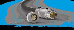
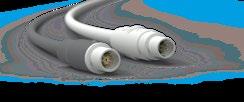
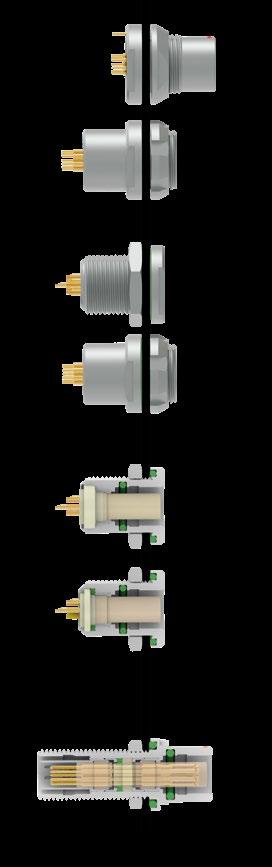
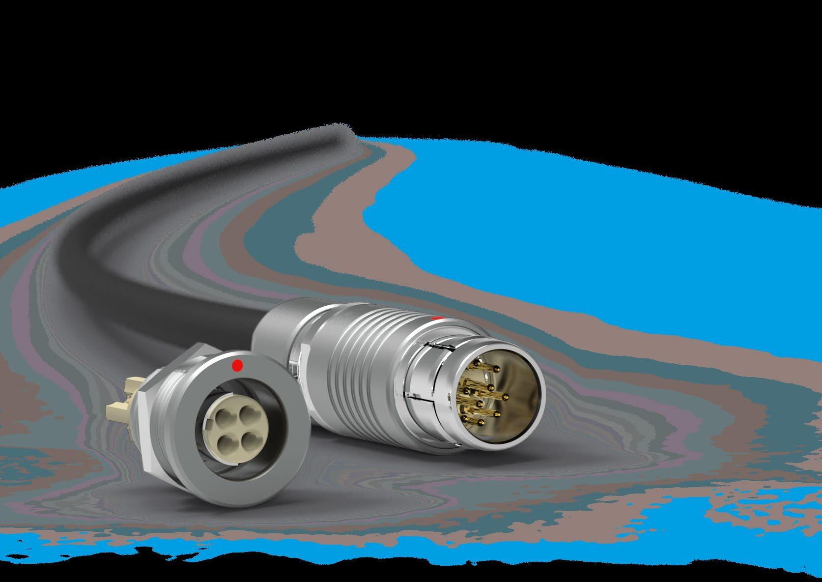
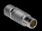
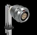
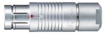
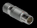
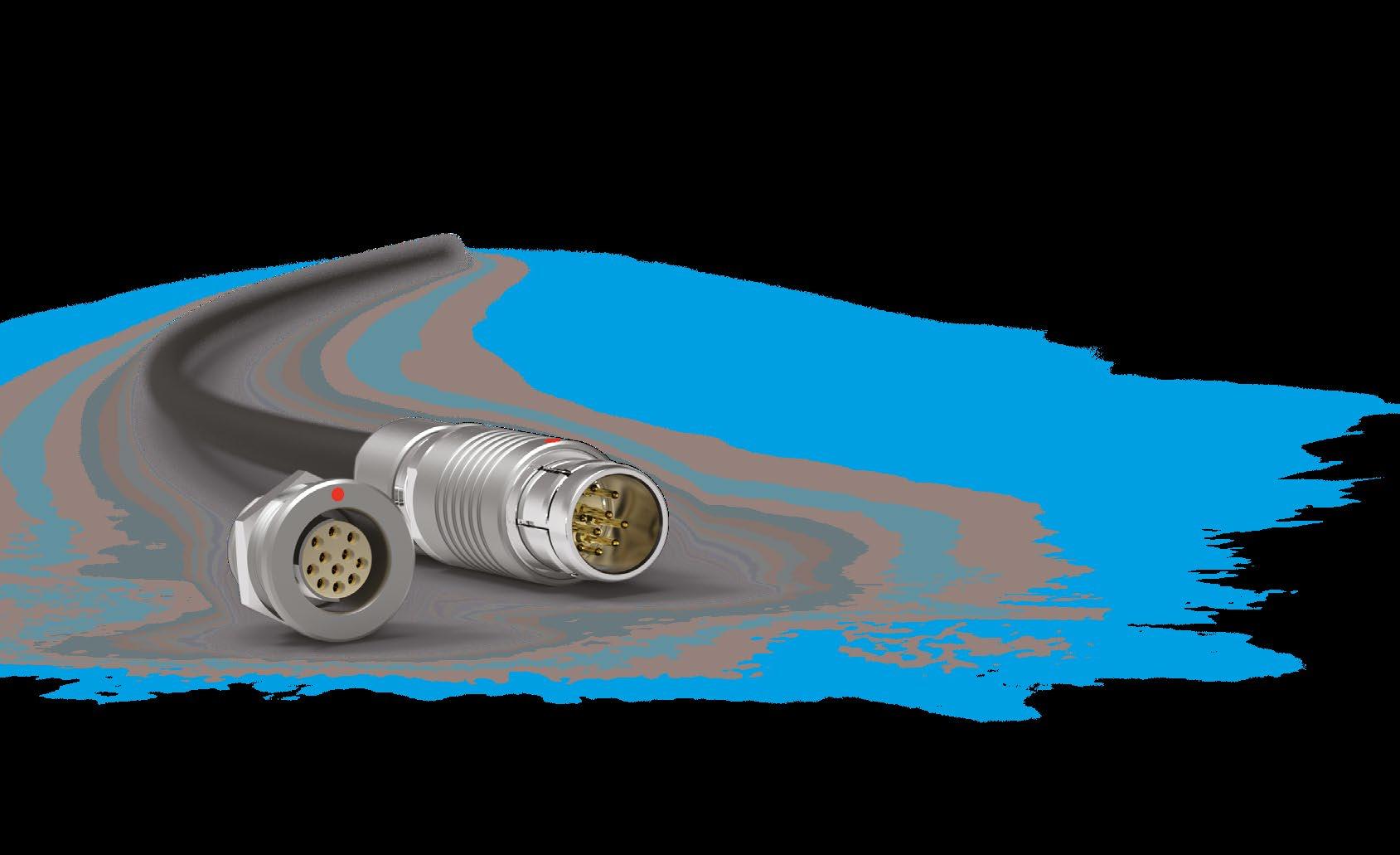
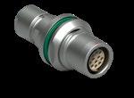
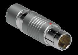
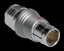
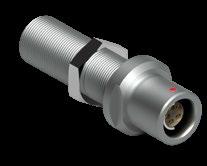
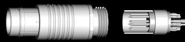
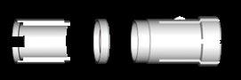
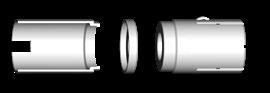
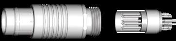
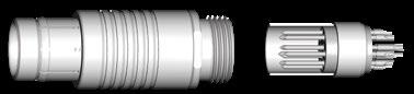
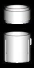
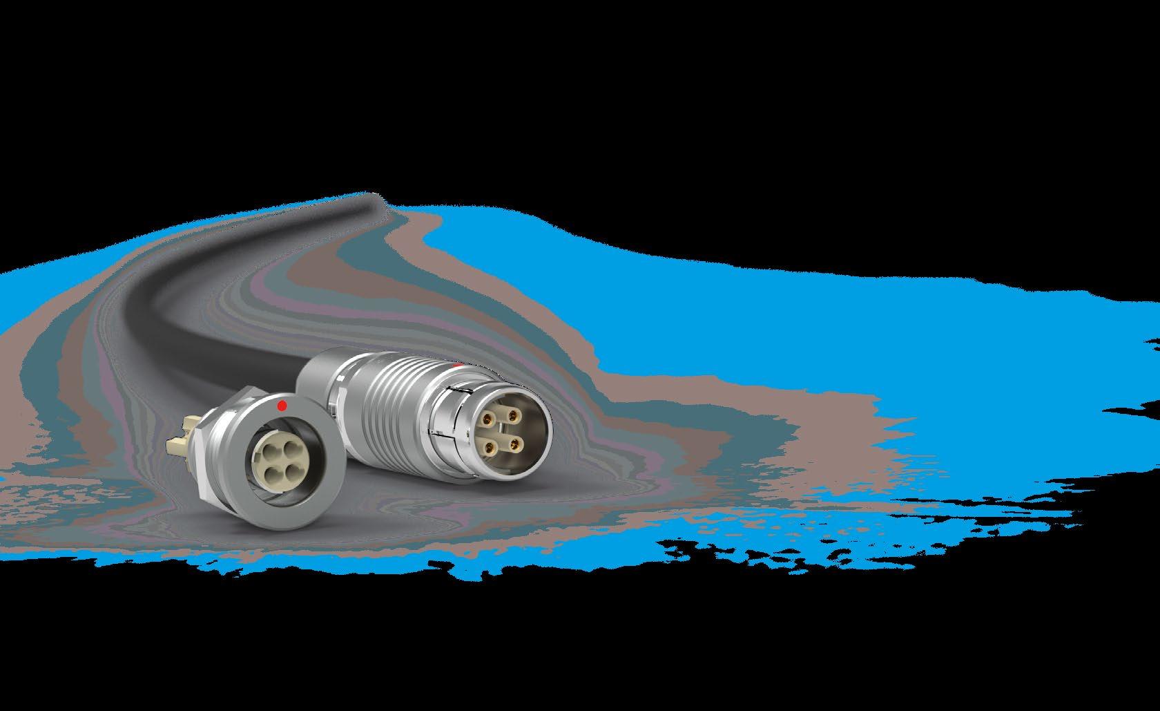
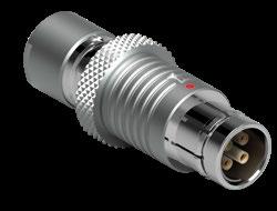
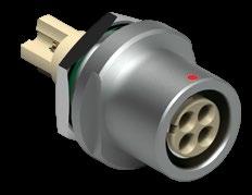
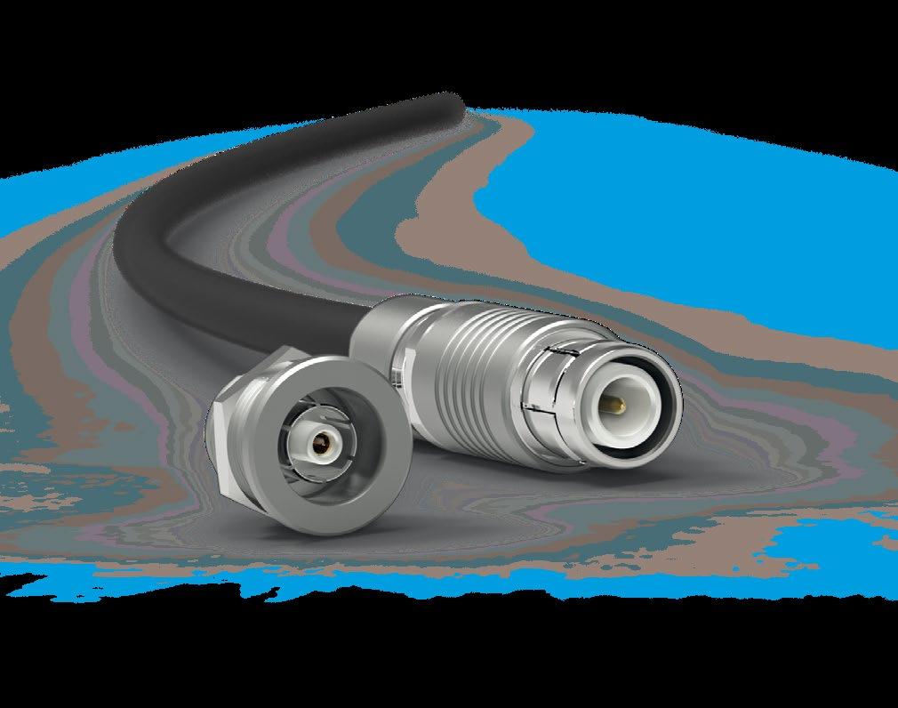
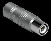
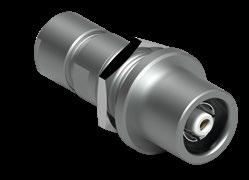
Fischer Connectors’ original push-pull automatic locking system is widely adopted by the industry for its ease of use, safety of mating and speed in connection and disconnection.
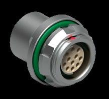
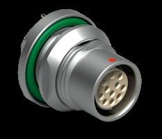
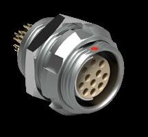
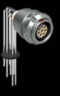
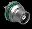
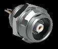
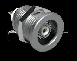
Receptacle
Receptacle
Receptacle
Receptacle
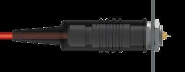
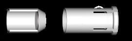
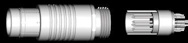
The plug has an outer sleeve, with flexible fingers, which slides forwards and backwards along the plug body.
The beveled edges are firmly captured by a locking groove located inside the receptacle.
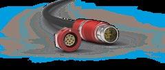
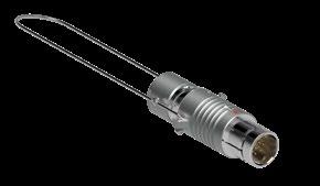
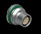
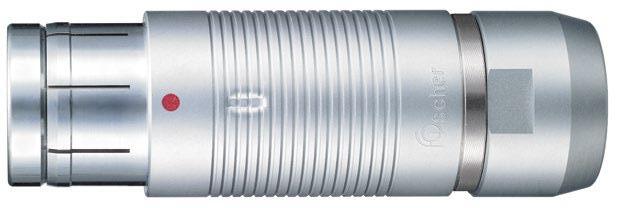
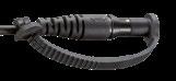
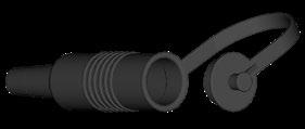
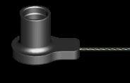
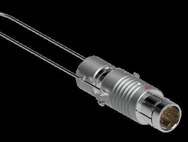
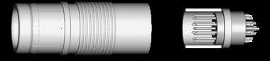
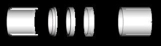
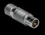
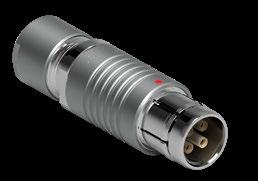
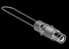
LANYARD
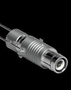
Combines push-pull automatic locking with an emergency release lanyard.
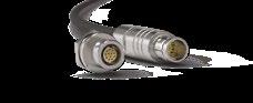
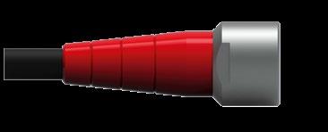
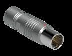
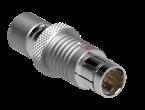
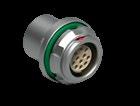
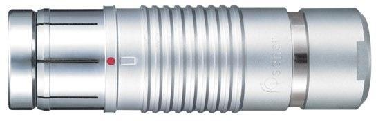
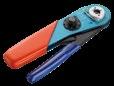
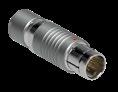
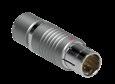
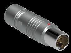
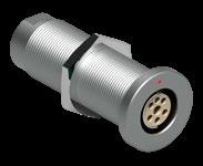
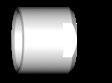
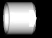
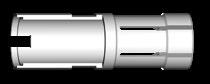
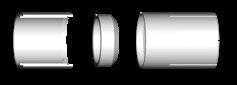
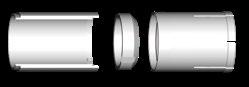
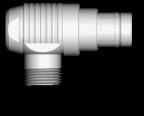
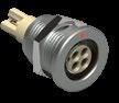
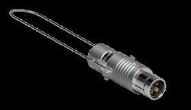
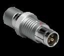
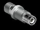
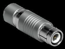
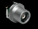
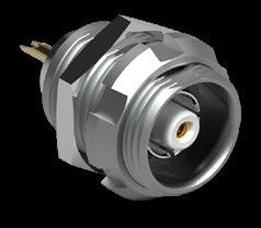
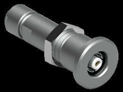
QUICK-RELEASE
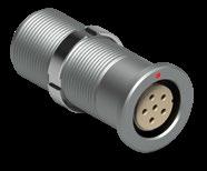
Designed without a locking mechanism for emergency release.
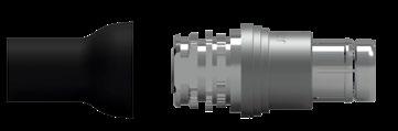
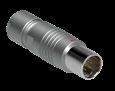
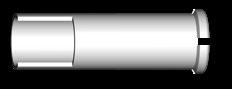
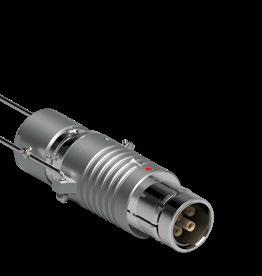
Designed without a snapping mechanism.
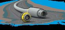
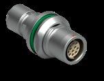
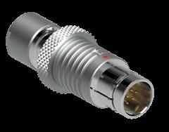
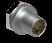
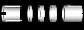
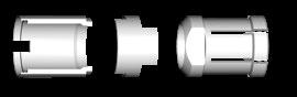
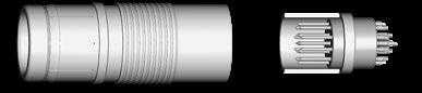
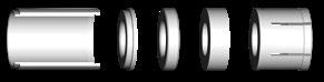
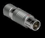
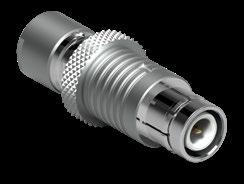
Features an integral safety locking ring to prevent unauthorized or unintentional disengagement.
Enables firm locking by circular movement with the plug’s outer sleeve and receptacle feature threading.
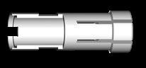
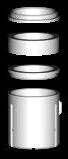
The beveled edges of the fingers are forced into the groove, securing the connection.
Pulling on the outer sleeve of the plug unlocks the latching mechanism.
The IP (Ingress Protection) classification system provides a reliable method of comparing relative levels of sealing between various connector products.
The protection level offered by a typical envelope is described in IEC 60529, published by the International Electrotechnical Commission (IEC).
While the first number describes the level of protection from solid objects, the second one relates to protection from liquids.
Tests performed during the design and qualification of Fischer Connectors’ environmentally sealed products are standardized to IP68 at a depth of 2 meters and for duration of 24 hours. Fischer Connectors’ hermetically sealed products achieve IP69.
The digits indicate conformity with the conditions summarized in the tables aside.
Non-protected
Protected against solid objects greater than 50 mm
Protected against solid objects greater than 12 mm
Protected against solid objects greater than 2.5 mm
Protected against solid objects greater than 1.0 mm
Dust protected Dust tight
2 3 4 5 6 7 8 9
Non-protected
Protected against dripping water
Protected against dripping water when filled, up to 15°
Protected against spraying water
Protected against splashing water
Protected against water jets
Protected against heavy seas
Protected against immersion effects
Protected against submersion
Protected against intense water jets SOLIDS 0 1 2 3 4 5 6
IP50 indoor unexposed applications
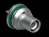
IP68 watertight sealing
Hermetic sealing
Each requires different sealing levels and, therefore, different connector solutions.
Typically for indoor or industrial applications, the required sealing level is IP50, since the device needs to be protected against dust but not exposed to water.
The IP50 rating can be improved with additional accessories like boots or protective sleeves.
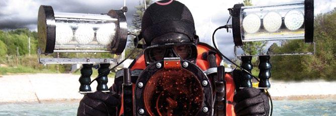
Typically for applications requiring outdoor use where they might be exposed to water submersion, rain, sand, mud or any other environmental stress.
Typically for applications requiring gas tightness like vacuum applications and pressurized vessels, immersed for long periods of time or exposed to strong jets.
100% of the hermetic pieces are tested with a leak testing instrument to ensure a leak smaller than 10-8 mbar l/s.


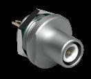
Depending on whether you need the space saving inside or outside the device
Also available in front or rear mounting
Depending on how you need to process your assembly
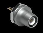
Rear mounting is commonly used for PCB mount
Hermetic has a specific sealing material for best sealing under high pressures
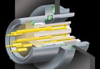
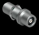
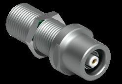
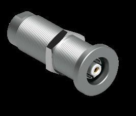
Hermetic panel bulkhead feedthrough
MATERIAL NAME
Chromium-plated brass Ruggedness -100 to +200°C Salt mist and mechanical resistance, cost efficiency, electrical conductivity
Aluminum Lightweight -100 to +200°C Lightweight
Stainless steel Cleaning / Radiation -100 to +350°C
PEI Sterilization -65 to +200°C
Corrosion resistance, surface cleanability, nuclear radiation and mechanical resistance
Sterilization in autoclave, EtO, Cidex, gamma radiation, Steris®, Sterrad®
PBT Insulation -65 to +135°C Electrical insulation, low temperature manipulation
ABS Cost efficiency -20 to +65°C
Disposable solutions, medical applications
PEEK High temperature -65 to +250°C
High temperature, high chemical and high radiation resistance
LCP High temperature -65 to +200°C High temperature and high chemical resistance
PBT Cost efficiency -65 to +135°C High chemical resistance, cost efficiency
PTFE Electrical insulation -65 to +160°C High dielectric strength, high chemical resistance
ABS Cost efficiency -20 to +65°C
Disposable solutions, good stability
FPM (Viton®) Hermeticity -20 to +200°C
Acids, weather, ozone, fuels, mineral and silicone oils, high vacuum, gamma rays
EPDM Low temperature -50 to +160°C Alcohol, weather, hot water, vapour, detergents, gamma rays
NBR Oil resistance -30 to +110°C Acids, mineral oils, petrol, weather, detergents
FVMQ High temperature oil resistance -55 to +200°C Mineral oils, alcohol, weather, hot water, detergents
TPE Soft accessories -55 to +130°C Very resistant, except to aromatic and chlorinated hydrocarbon
Silicone based resin IP68 sealing -55 to +200°C Mineral oils, acids, alkalines, inorganic saline solutions
Epoxy based resin Hermeticity -65 to +150°C High chemical and radiation resistance
To protect users from contact with dangerous voltage, most of Fischer Connectors’ products are available in two versions :
STANDARD A POLARITY
The contacts of the receptacle are protected against accidental touch. Recommended when voltage is present on the receptacle.
INVERTED Z POLARITY
The contacts of the plug are protected against accidental touch. Recommended when voltage is present on the plug.
Maximum voltage difference that can be applied before the occurrence of a disruptive discharge between mutually insulated portions of a connector or between insulated portions and the ground.
Voltage level at which the connector is tested during the qualification test. This value represents the upper physical limit. It is usually set at 75% of breakdown value.
Voltage under which the connector will actually work in the equipment over the normal expected lifetime and in typical environmental conditions.
For connectors in common applications, IEC60664 is in particular recommended. This specification uses creepage distance instead of test voltage as a calculation basis for the operating voltage, taking into account the above-mentioned long-term effects. It is similar to German VDE 0110; typical applications are classified in insulation groups depending on their exposure to pollution.
Fischer Connectors recommends the use of IEC60664 in general multipole connector specifications, unless other more specific standards or regulations are applicable to the design. For example, IEC 60601 provides adequate special guidelines for medical devices.
All values given here are valid for mated connectors, provided that termination of connectors has been completed with adequate cable and following correct termination procedures. Other standards recommend a calculation using the test voltage as a basis with the application of a safety factor. For example, BS 9520 recommends setting the operating voltage at:
0.33 x test voltage for 500V <test voltage <3kV
0.66 x test voltage for test voltage >3kV
Similar recommendations are provided in EIA-364-20 and former MILSTD-1344 method 3001.
DERATING CURVE DERIVED FROM THE BASIC CURVE
cable)
When selecting a connector, attention must be paid to the fact that the temperature rise caused by current must be added to the ambient temperature and that the resulting value shall not exceed the upper temperature limit of the materials, listed under the “Operating temperatures” sections and plotted as a vertical line on the graphs shown in Figure 1.
The current-carrying capacity may be further limited by external factors, for example the size of the wire and the cable characteristics. This upper current limit is plotted as a horizontal line on the graphs shown in Figure 1.
The current values listed under “Electrical & contact configurations” were measured in our test laboratory according to IEC 60512-5-2: Current-carrying capacity test, Test 5b: Current-temperature derating. They are the currents that create a temperature rise of 40 °C (unless otherwise specified) within the connectors due to the self-generated heat, and they belong to the basic curve shown in Figure 1.
The maximum permissible current (I) as defined by the above mentioned IEC standard is the basic curve derated by a factor of 0.8 to account for manufacturing tolerances and uncertainty in measurements.
The operating area is defined by the surface below the derated curve and limited on top by the upper current limit.
The current values listed under “Electrical & contact configurations” are valid for each contact. For coaxial and triaxial connectors, the current is valid for the center and the outer contact.
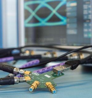
When a signal is emitted at the transmitter, it must undergo minimal distortion across the system (transmitter, connectors, cable, receiver) to be properly recovered at the receiver.
Types of signal distortion across the transmission link:
Return loss: When the impedances of two interfaced media do not match (i.e., transmitter/connector, connector/cable, ...), some parts of the signal will reflect back towards the source and be lost. The amount of this loss comes from impedance mismatch and is characterized by the return loss.
Insertion loss: Insertion loss describes the attenuation of the signal along the transmission path. This mainly arises from losses both in the dielectric and the conductors.
Crosstalk: Signals running in close-lying channels are likely to couple to one another. This is described as crosstalk terms.
Noise: Unwanted interferences which could either be external or internal to the system itself might add up to the original signal and cause distortion. For instance, internal interferences can be linked to the noise generated from the transmitter or receiver.
CONNECTOR DESIGN RULES TO OPTIMIZE DATA TRANSMISSION
At a system level, the return loss, insertion loss, crosstalk and noise are critical parameters to ensure high quality data transmission. However, impedance and crosstalk play a more prominent role at the connector level.
Connector with optimized impedance
To optimize impedance matching, the following factors must be considered: Contact diameter, interaxial contact distance, contact form factor, and the dielectric constant of all the components (i.e., type of material).
Figures 1 and 2 illustrate the notion of impedance matching in which the green area depicts the tolerated range: Fig. 1 shows a connector with poor impedance-matching, while Fig. 2, shows a connector with optimized impedance matching.
To minimize crosstalk, the geometrical distribution of the contacts as well as the contact layout (i.e., signal attribution to specific contacts) are critical.
Figures 3 and 4 illustrate the latter by displaying the crosstalk for two different contact layouts: Fig. 3 shows a connector where the contact layout was not optimized, while Fig. 4 shows a reduced crosstalk noise level which was achieved as a result of an optimized contact layout.
DATA PROTOCOLS
Data protocols provide us the normative values of data transmission parameters (ex. Insertion Loss, Return Loss, Crosstalk, Noise). This provides a means of ensuring that the various components of a system (transmitter, connectors, cable, receiver) work together and allow for an optimized transmission of the data streams.
Two complementary methods can be used to assess the system’s capability of transmitting a certain high-speed data transmission protocol in terms of signal quality and transmission speeds: Numerical simulations (connector only) and Vector Network Analyzer (VNA) measurements (i.e., cable and connector).
Typical high-speed data transmision protocols are USB, Ethernet and standard protocol for the simultaneous transmission of audio and video.
SYMBOL
4 wires for USB 2.0 up to 480 Mbit/s
9 wires for USB 3.2 Gen 1 up to 5 Gbit/s
9 wires for USB 3.2 Gen 2 up to 10 Gbit/s
FISCHER SERIES PERFORMANCE UP TO:
2 wires for SPE up to 1 Gbit/s (1000BASE-T1)
4 wires for Ethernet up to 100 Mbit/s (100BASE-TX)
8 wires for Ethernet up to 10 Gbit/s (10GBASE-T)
19 wires for standard audio/video protocol up to 10.2 Gbit/s
SERIES
2.0
Fischer Connectors’ skilled technical and support teams can help you build the perfect system by analyzing your specific application and needs. Please contact your local sales representative for more details.
Most versatile
Pre-installed contacts
Qualified assemblers required
Can be produced with any type of contact block material and accept a wide range of wire sizes.
Contacts are pre-installed in the insulator block, and the wires can be terminated with any appropriately sized soldering iron.
May require operators who are qualified in specialized soldering techniques.
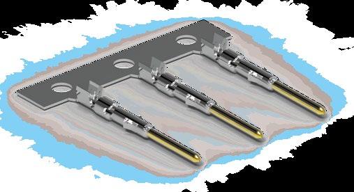
PCB CONTACTS
PCB or Flex circuit mount
Reduced pin diameter
Wave soldering
Selectively annealed area
Special tools required
Limited range of wire sizes
Designed to be mounted directly onto a PCB or flex circuit, can be used in wave soldering operations for faster production assembly.
Preferred for high rates of data transmission due to the low distance to the board that their integration allows. This helps reducing signal perturbations.
PCB pins are generally used on rear mounted panel connectors.
Each contact has a selectively annealed area which is deformed during assembly by specialized tooling to assure proper termination of the wire to the contact.
Commonly used for field termination or repair, as no soldering process is required.
Not available for sealed or hermetic connectors.
High volume
Automated cable assembly
Disposable applications
High optical performance
IP67 unmated
UPC & APC polishing
Optimized for very high volume and automated cable assembly.
Come on specific reels to be accommodated in automated cable assembly machines.
Mainly used in disposable applications due to their limited number of mating cycles.
The FiberOptic termini rely on butt-joint technology commonly used in the telecom industry to ensure ultra-low insertion and return losses.
A unique sealing feature on the termini allows easy cleaning and device protection even unmated (IP67) without compromising on the alignment once mated.
Guaranteed, tested and certified optical performance platform using high precision polishing process.
The alignment sleeve parts are located in a removable mate adapter for easy maintenance, replacement and cleaning.
OVERMOLDED STRAIGHT & RIGHT ANGLE BEND RELIEF
Can accommodate a wide range of cable diameters
Wide choice of colors and materials (e.g. polyurethane, silicon, etc.)
Best protection to improve cable flex life
Improves mechanical protection on the whole interface :
Prevents contamination in highly dusty environments
Protects both plug and receptacle
Enhances sealing
CABLE BEND RELIEF
Tool-free terminations for field installations :
High quality and improved protection
Wide range of colors for easy cable identification
Can accommodate a wide range of cable diameters
Allows submersion with adhesive versions :
Ideal for quick prototyping
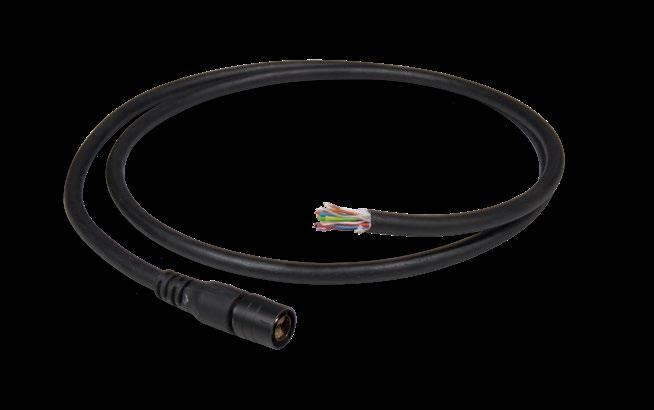
Can accommodate a wide range of cable diameters and multiple cable output
Protects exposed wires
VERTICAL
INTEGRATION
Connectors
Components
Cables
Fischer Connectors provides system designers with everything they need to put together the right
Thanks to the most modern ISO certified cable assembly facilities in Europe, North America and Asia Pacific, our engineering and manufacturing experts ensure short lead times to meet your
EXPERTISE
Design
Manufacturing
Testing
RELIABILITY
Sealing
Sterilization
Data transmission
Our engineers work closely with your team to find the right solution for the most demanding applications by integrating precision connectors, components, parts, and engineered cables.
Fischer Connectors’ skilled technical and support teams help you build the perfect cable assembly for your unique application, providing advice through design, prototype, assembly, testing, manufacturing, installation, and beyond.
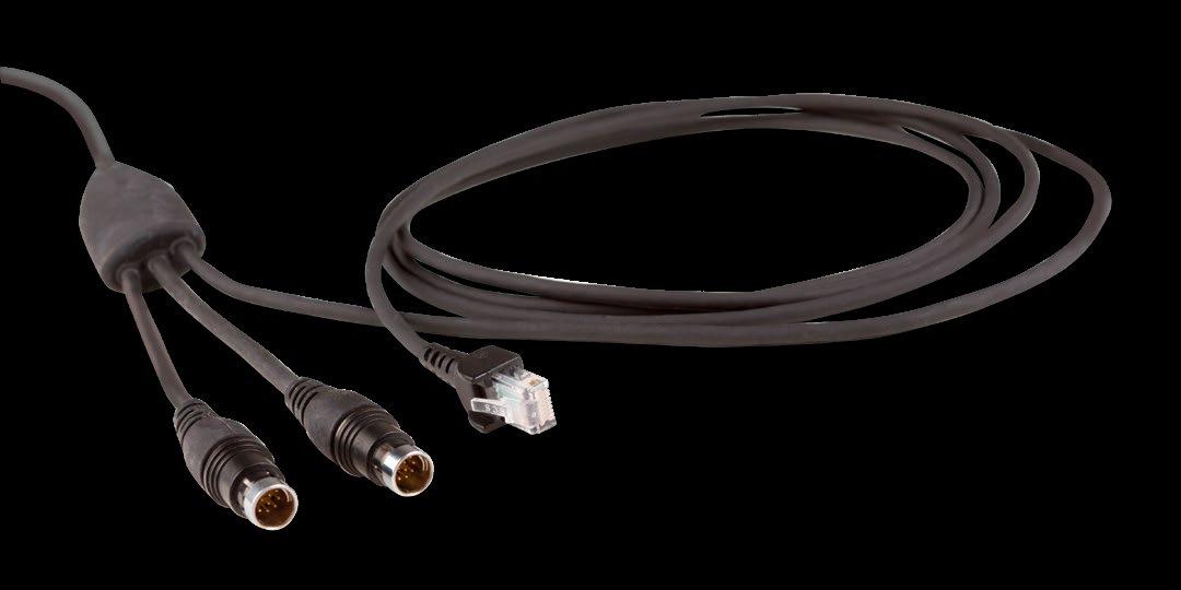
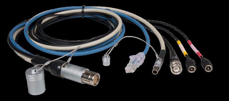
High-performance rugged and submersible cable assemblies for the defense and marine markets
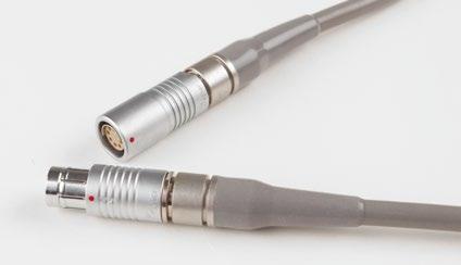
Silicone overmolded solution for high heat protection and maximum flexibility in the medical industry
High-speed transmission of electrical, power, and optical signals
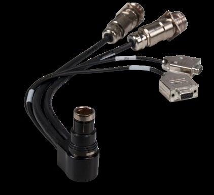
Custom and application-specific cable harnesses
Integration in medical devices
High temperature applications
Overmolded cable assemblies, including thermoplastic & silicone
Wiring harness assemblies
Rugged & submersible cable solutions
Third-party connector integration
Right-angle overmolds
Custom overmolds with multi-cable exits
Potting or heat shrink
Automated strip and crimp
Colored overmolding
Low cost and disposable options
With our worldwide connectors and cable assembly network, located in Europe, North America and Asia Pacific, we provide our customers with quick turnarounds around the globe.
By purchasing cable assemblies, connectors and manufacturing from one place, you deal with one vendor, pay one bill, and reduce the time and the risk it takes to coordinate your project.
Overmolding, including right-angle and custom connections, silicone and low friction cables, are all part of the business. We have overmolding machines for both polyurethane and silicone.
Companies that use Fischer Connectors for both their connectors and assembly solutions can see significant savings over the cost of handling each vendor separately.

We build cable assemblies to the same rigorous quality standards as we build our connectors. Whether you’re looking for a simple or complex assembly, Fischer Connectors is able to deliver exactly what you need, when you need it.
Fischer Connectors has helped hundreds of customers find their unique cable assembly solution that fulfills technical, quality and cost requirements.
From prototyping, design validation, testing and delivery, we support your project from the beginning to the end.
Our team of experts is at your service to recommend the best solution for your connectivity challenges and turn them into a success story.
Thermoplastic overmolds for the Fischer Core Series, Fischer MiniMaxTM Series and Fischer FiberOptic Series
Silicone overmolds with low friction coatings for medical and high temperature applications
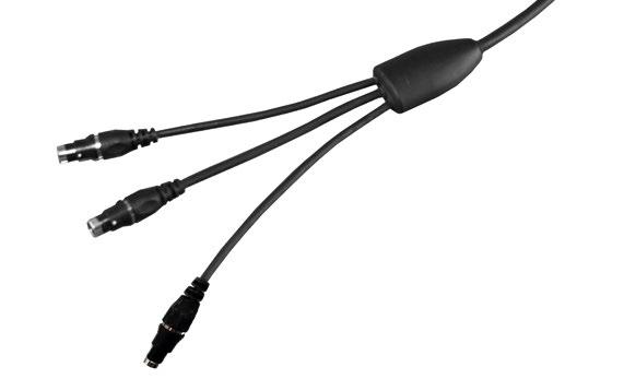
Thermoplastic overmolds with custom cable breakouts
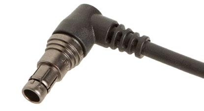
Right-angle thermoplastic overmolds for the Fischer Core Series and Fischer UltiMateTM Series
Thermoplastic overmolds for the Fischer UltiMateTM Series
Custom thermoplastic overmolds for multi-cable exits
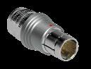
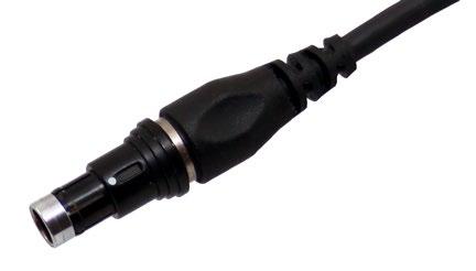
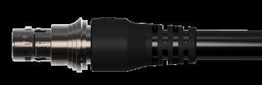
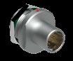
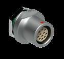
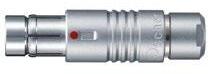
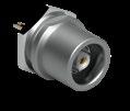
BODY STYLES S SC SOV SA SV SS
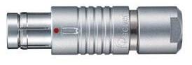
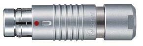
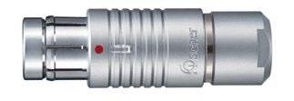
Locking system Push-pull Quick-release Non-locking Push-pull Push-pull Push-pull
Sealing IP50 / IP68 IP50 / IP68 IP50 / IP68 IP50 / IP68 IP50 / IP68 IP50 / IP68
Design Standard Standard Standard Lanyard Tamperproof Short/Overmolding
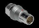
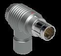
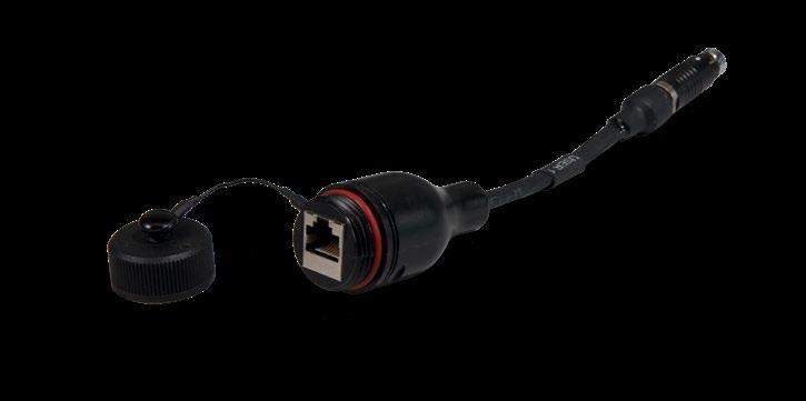
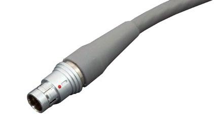
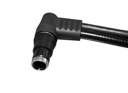
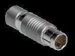
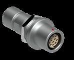
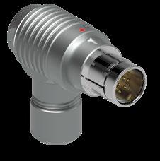
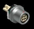
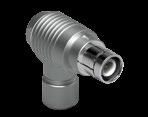
BODY STYLES SSC WSO
Locking system Quick-release Push-pull
Sealing IP50 / IP68 IP50 / IP68
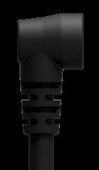
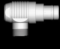
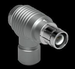
Design Short/Overmolding Right-angle
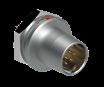
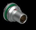
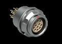
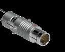
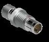
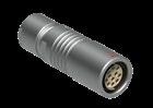
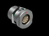
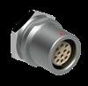
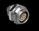
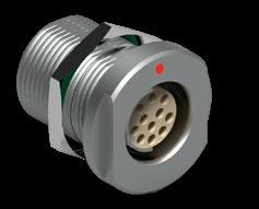
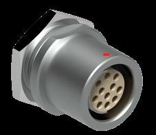
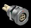
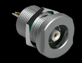
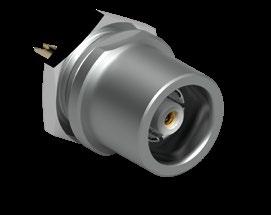
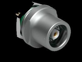
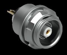
BODY STYLES SF SFU SFE
Locking system Non-locking Non-locking
Sealing IP50 IP68 Hermetic
Design Front-projecting Front-projecting
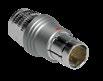
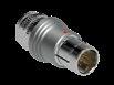
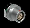
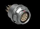
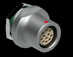
BODY STYLES SFPU SFPE
Locking system Non-locking
Sealing IP68 Hermetic
Design Front-projecting
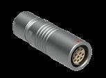
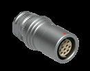
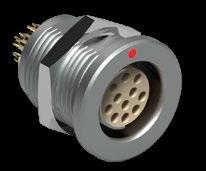
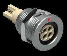
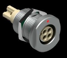
BODY STYLES K KE KS KSE
Sealing IP50 IP68 IP50 IP68
Design Standard Short/Overmolding

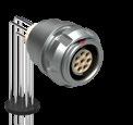
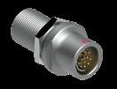
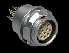
BODY STYLES DG DGP WDE
Sealing IP50 IP50 Hermetic
Design Completely threaded Bulkhead feedthrough Solder/Crimp PCB
PANEL FRONT MOUNTED
BODY STYLES
Sealing IP50 IP50 IP68 Hermetic IP68 Hermetic IP50 IP68
Design Rear-projecting Front-projecting Rear-projecting Front-projecting Cable mounted Cable mounted
PANEL REAR MOUNTED
BODY STYLES
Sealing IP50 IP50 IP68 Hermetic IP68 Hermetic IP68
Design Rear-projecting Right-angle PCB Rear-projecting Front-projecting Cable mounted
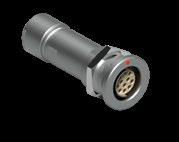
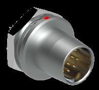
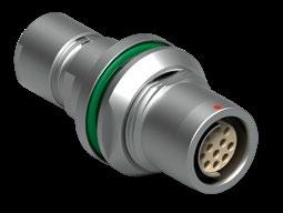
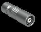
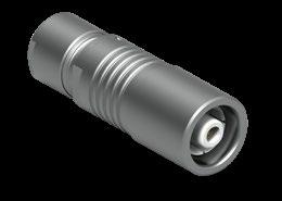
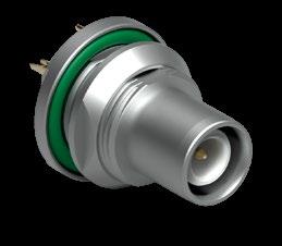
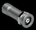
S - SS - WSO
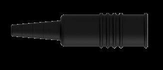
Fischer Connectors’ original push-pull automatic locking is widely adopted by the industry for its ease of use, safety of mating and speed in connection and disconnection.
Fully secured against accidental disconnection, it provides unparalleled signal integrity.
Integrated into the connector housing, it is ideal for compact product design.
For more details on Fischer Connectors’ locking systems, visit: www.fischerconnectors.com
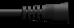
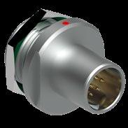
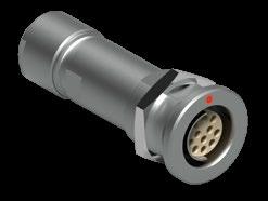
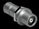
Fischer Connectors’ quick-release plugs are designed without locking mechanism for emergency release.
Quick-release plugs snap into the receptacle with an audible “click”.
A strong pull on the cable will allow unmating of the plug.
Specially suited to avoid injuries to the users and damages to the material in case of accidental stress.
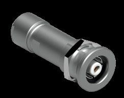
The lanyard plug combines push-pull automatic locking with an release lanyard.
A strong pull on the lanyard will unlock the latching mechanism.
Specially suited to allow quick unmating on the field.
Secure locking when cable pulled Pull the lanyard to unlock
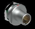
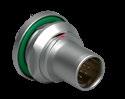
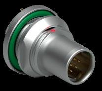
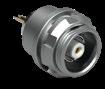
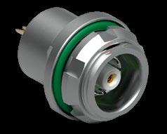
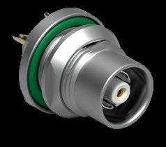
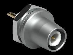
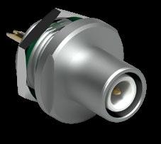
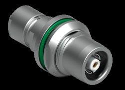
SOV - SF - SFE/SFU - SFPE/SFPU
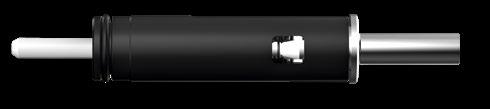
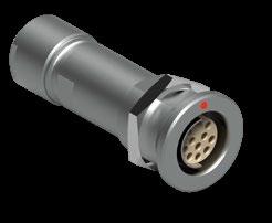
Our non-locking plugs are designed without clicking mechanism.
A soft pull on the connector will release the plug.
Specially suitable for connections with limited accessibility and/or requiring no locking.
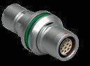
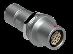
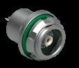
Our tamperproof plug features an integral safety locking ring to prevent unauthorized or unintentional release.
When tightened, the knurled ring will prevent unmating of the plug.
Specially suitable for applications involving high voltage or current.
No clicking
Plug released when connector pulled
Secure locking when knurled ring tightened
Untighten the knurled ring and pull the outer sleeve to unlock
1) Pictures represent standard S plug, but values can be extended to all cable mounted plugs, except for SS/SSC body styles.
2) For max cable ø, values in parenthesis are valid for sealed connectors (IP68).
How to build a part number Fischer Connectors Core Series Brass is built on a modular design and offers over 20,000 standard configurations. Refer to the table aside to find the information you need to build the part number to order your selected connector. For customized solutions, please contact us.
NUMBER EXAMPLES
S 102 A
S cable mounted plug in Size 102 with 7 (multipole) low voltage male contacts and following options.
D 102 A
D panel mounted receptacle in Size 102 with 7 (multipole) low voltage female contacts and following options.
Cable mounted plugs Size As standard rule
S/SC SOV SA SV SS/SSC WSO 102 103
Cable mounted receptacles
K/KE KS/KSE
A = male contacts on plug and female contacts on receptacle
Z = female contacts on plug and male contacts on receptacle
Panel mounted cable receptacles Exceptions
DK/DKE DKBE
Multipole high voltage Mixed high voltage Panel mounted receptacles
D DEU/DEE DB DBEU/DBEE DBP DBPU/DBPE DBPLU/ DBPLE DG/DGP DBPC WDE
Panel mounted plugs
SF SFU/SFE SFPU/SFPE
Contact configuration Options* Cable clamp sets for cable mounted plugs & receptacles
See page B2-42 for multipole low voltage / See page B3-24 for others
056 130 +
Natural chrome housing, PEEK contact blocks with solder contacts, keying code 1 and clamp nut without bend relief.
056 130 Not applicable as panel mounted
Natural chrome housing, PEEK contact blocks with solder contacts and keying code 1.
Three-digit number specific for each pin layout
Specific suffix corresponding to selected options
Housing color
Below cable clamp sets should be ordered separately
Multipole low voltage Triax
Natural chrome Black chrome Example : S 102 A056 - 130 +
Contact block insulating material Clamp set ordering line E3 102.5/2.0
PEEK PTFE PBT See page B 2-42
Contact type
Solder Crimp PCB
Mechanical coding of the contact block
Clamp nut type & color
Other options
Below cable clamp sets are included with connector
Coax low voltage Coax high voltage
Multipole high voltage Mixed high voltage Mixed coax
Shielded (S) or Environmental (E) cable clamp set diameter should be added to the connector part number separated by ø. Insulating clamp set ø (104, 105 and 106 Sizes) should be added to the connector part number separated by ø and followed by UI (Unshielded Insulated).
Examples : for Shielded S clamp sets K 103 A002-600 ø6.2 or environmental E clamp sets KE 103 A002-600 ø6.2
Example : S 104 A062-130 ø6.6 - UI
Cable bend reliefs
Protective sleeves
Soft caps
Metal caps
Spacers
Washers
Mounting nuts
Spanners / Wrenches
Crimping tools
Tools for crimp contacts and high voltage contacts
See Accessories section, page B 6-2. See Tooling section, page B 6-19.
5) Ethernet 1 Gbit/s
6) Standard protocol for simultaneous transmission of audio and video,
5) UHD-Video 18 Gbit/s
to 10.2 Gbit/s
7)
The dimension of panel cut-outs varies according to the body style and size of the panel mounted connector.
Refer to the tables aside and below for more details.
Check details in technical drawings on our web site: www.fischerconnectors.com
PANEL MOUNTED RECEPTACLES
1) Coax High Voltage DEE 102 AZ 025: ø11.1 (see page B 3-33).
All dimensions and images shown are in millimeters and are for reference only.
PANEL MOUNTED PLUGS
PANEL MOUNTED CABLE RECEPTACLES
The standard Fischer Connectors shells are nickel plated brass with natural (silver) chrome finish. Black chrome finish is available as an option; see Options pages B 2-35 and B 3-26. Internal piece parts are nickel plated brass. When warranted by an extreme environment, in most cases stainless steel can be substituted for all metal parts.
Metal parts
Shell (Housing), clamp nut, decorative slotted nut
Plug body, cable clamp, inner sleeve, spacers and rings, nuts and washers Brass CuZn39Pb3
/ UNS C
CW614N / UNS C 38500 Nickel SAE-AMS-QQ-N-290 / SAE-AMS2404
Contacts Male (solder) Brass CuZn39Pb3 CW614N / UNS C 38500 1 µm Gold over Nickel MIL-DTL-45204D / Type 1 + ASTM B488
Female, Male (crimp) Bronze CuSn4Zn4Pb4 CW456K / ASTM B 139 / UNS C 54400
Other material and surface treatments are available on request.
Contact blocks and other insulators for our standard connectors are manufactured from high performance engineering plastic materials. The standard materials of each connector series are listed under Electrical & Contact configurations in pages B 2-2 through B 5-2. Ceramics and other dielectrics are available on special order.
Insulator and sealing International symbol Flammability
Insulator PEEK - PTFE - PBT UL 94 V-O
Interface O-rings (receptacles) FPM (Viton ®) / EPDM -
Sealant material - IP68 (receptacles) - Hermetic Silicon compound Epoxy compound UL 94 V-O UL 94 HB
Cable sealing (plugs) - IP68
TPE-S UL 94 HB
Our products are RoHs compliant and conform with the EC Directives 2002/95/EC.
Sealed connectors are fitted with O-rings and cable sealing gaskets.
The standard materials are:
FPM (Viton®) for O-rings
TPE (Thermoplastic Elastomers) for cable seals, protective sleeves and strain reliefs.
Compound and trade name
Chemical name Excellent resistance to FPM (Viton®)
Fluoro Elastomer
EPDM, EPM or EPR
TPE-S, TPE-O (Thermoplastic Elastomer)
Ethylene Propylene
Diene Elastomer
Styrene-EthyleneButadiene-Styrene
Acids, weather, ozone, fuels, mineral and silicone oils, high vacuum, gamma rays
Alcohol, weather, hot water, vapor, brake fluids, detergents, gamma rays
Very resistant, except to aromated and chlorinated hydrocarbons
Please note that as an elastomer reaches its lower temperature limit, it becomes rigid and loses the flexibility required for connector mating and unmating. If sealed connectors have to be manipulated at low temperatures, the O-rings in the mating area has to be of a material with a considerably lower temperature limit.
The elastomers listed below represent presently available materials, which Fischer Connectors can substitute when required by an application. Not all materials are available in all shapes and sizes so please check with us for details.
Characteristic
Sealing performance
Unsealed connectors (mated)
Plugs (mated) with general purpose sealed clamps 1)
Receptacles "U" body style
Receptacles "E" body style
Operating temperature range
Corrosion resistance 3)
IP50
IP68
IP69
IP68
IEC 60529
Hermetic: Tested: <10-8 mbar l/s IEC 60068-2-17 test Qk method 3, alternative b
IP69 IEC 60529
See details on page A-9 and B1-15 IEC 60512-6-11 i+j / IEC 60068-2-14-Nb
Salt mist, 1,000 hours, 5% salt solution, 35°C IEC 60068-2-11 test Ka MIL-STD-202 method 101 EIA-364-26
Endurance 10,000 mating cycles IEC 60512-9-1 / EIA-364-09
Vibration
10 to 2000 Hz, 1.5 mm or 15g, 12 sweep cycles per axis, 20 minutes per 10-2000-10 Hz sweep cycle, no discontinuity > 1us MIL-STD-202 method 204 condition B
Radiation resistance 2) Unsealed connectors PEEK: 107 Gy(=1000M Rads)
Sealed receptacles "E" FPM (Viton®) O-rings 105 Gy (=10M Rads)
1) The sealing performance can be affected by the long term quality of the cable.
2) For information only. Not tested by Fischer Connectors.
3) Plug and receptacle in mated position or with cap when unmated. For Brass connectors only. Aluminum version not recommended for Marine use. Preserved mechanical and electrical functionality. Visual aspect might be altered.
Most of our connectors are completely sterilizable in autoclave, Cidex® , EtO, gamma radiation, Steris® or Sterrad®. Please contact us for more details. For more information visit: www.fischerconnectors.com
Characteristic
60512-2-1, Test 2a IEC 60512-2-2, Test 2b
Insulation resistance > 1010Ω IEC 60512-3-1-3a Method C
All dimensions and images shown are in millimeters and are for reference only.
1)
The temperature ranges quoted by the manufacturers of the plastic materials are usually the absolute maximum values. When exposed to the mechanical and electrical stresses present in a connector, these values are often unrealistic. If a composite connector system including accessories is used, then the item with the lowest temperature performance will dictate the operating temperature limit of the system. The table below shows our recommended operating temperature ranges.
1 Sealant
2 Insulator
3
4
5 Cable clamp
7 Protective
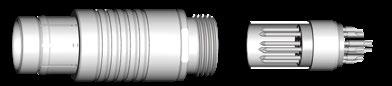
Our contact blocks are engineered with arc-shape metal guides, which ensure precise alignment of connectors during the mating process.
This guiding mechanism provides:
Increased safety and user friendliness by preventing misconnection. Easy mating cycles, can be blind-mated.
Increased equipment life span by optimally protecting the contacts.
All multipole body styles are mechanically coded. Code 1 is the standard, but other codes can be requested.
Other keying codes are available on request, please contact us. Images are here for information only and do not reflect always the reality.
Keying codes options
All multipole body styles are mechanically coded. Code 1 is the standard, but other codes can be requested.
All dimensions and images shown are in millimeters and are for reference only.
CABLE MOUNTED
styles (S/SC; SOV; SA; SV; SS/SSC; WSO)
2- 3
2- 4
PANEL MOUNTED
(SF; SFU/E; SFPU/E)
CABLE MOUNTED
styles (D; DEU/E; DB; DBEU/E; DBP; DBPU/E; DBPLU/E; DG; DGP; DBPC; WDE)
MOUNTED CABLE

Protection
Unsealed (IP50)
Sealed up to IP68
Locking system Friction
Push-pull
Quick-release
Lanyard
Tamperproof
Crimp
Contacts
Housing color
Design
Solder
Natural chrome
References to detailed information
Sealing categories, page A-6
Locking systems, page A-5
Electrical & configurations, page B 2-23
Options, page B 2-35 Black chrome
Shortened body
Straight Right-angle
Cable clamp sets
Cabling
Overmoldable
Heat shrinkable
Cable
Accessories
Body styles, chapter B1-2
Cable clamp sets, page B 2-39
reliefs Accessories, section B 6-2 Protective
Sealing
Technical dimensions, page B 2-4
For more information visit our website www.fischerconnectors.com/ technical
BODY STYLE
Torque [Nm] are recommended values that may be influenced by the characteristics of the cable jacket. Tests have to be made to evaluate the exact values. To secure the cable clamp nut, we recommend the use of thread locking adhesive.
All dimensions and images shown are in millimeters and are for reference only.
SS/SSC
BODY STYLES
WSO
BODY STYLE
WSO is available for different cable orientations. When ordering, choose which suffix to use in cable orientations figure. Example: WSO 102 A056 -130+ with standard down cable orientation WSO 102 A056 -130 -9H with left cable orientation
Body style
Protection
Unsealed (IP50)
Sealed up to IP68
Contacts Crimp
Solder
Natural chrome
Housing
Design
Cabling
Black chrome
Shortened body
Straight
Right-angle
Cable clamp sets
Overmoldable
Heat shrinkable
Cable bend reliefs
Accessories
Protective sleeves
Sealing caps
102 Size
Size
References to detailed information
Sealing categories, page A-6
Electrical & contact configurations, page B 2-23
Options, page B 2-35
Body styles, chapter B 1-3
Cable clamp set, page B 2-39
Accessories, section B 6-2
Technical dimensions, page B 2-8
For more information visit our website www.fischerconnectors.com/technical 103 Size
K/KE
BODY STYLES
KS/KSE
BODY STYLES
Torque [Nm] are recommended values that may be influenced by the characteristics of the cable jacket. Tests have to be made to evaluate the exact values. To secure the cable clamp nut, we recommend the use of thread locking adhesive.
Unsealed (IP50)
Protection
Sealed up to IP68
Hermetic
Crimp
Contacts
Housing
Design
Assembly
Right-angle
Flush
Front-projecting
Bulkhead feedthrough
Front-mounting
Rear-mounting
Sealing caps
Spacers
Accessories
Color-coded washers
Grounding washers
Locking washers
References to detailed information
Sealing categories, page A-6
Electrical & contact configurations, page B 2-23
Options, page B 2-38
Body styles, chapter B1-3
Accessories, section B 6-2
Technical dimensions, page B 2-11
For more information


Protection
Unsealed (IP50)
Sealed up to IP68
Hermetic
Crimp
Contacts
Housing
Design
Solder
PCB
Natural chrome
Assembly
Accessories
Sealing categories, page A-6
Electrical & contact configurations, page B 2-23
Options, page B 2-38 Black chrome
Right-angle
Flush
Front-projecting
Bulkhead feedthrough
Front-mounting
Rear-mounting
Sealing caps
Spacers
Color-coded washers
Grounding washers
Locking washers
Body styles, chapter B 1-3
Accessories, section B 6-2
Technical dimensions, page B 2-13
For more information visit our website www.fischerconnectors.com/ technical
Torque [Nm] are recommended values that may be influenced by the quality of the panel surface under the nut. Tests have to be made to evaluate the exact values.
All dimensions and images shown are in millimeters and are for reference only.
Torque [Nm] are recommended values that may be influenced by the quality of the panel surface under the nut. Tests
DBP BODY STYLE
Please contact
1 Assembly tool for decorative slotted nut, see Tooling section, page B 6-20, for details.
Torque [Nm] are recommended values that may be influenced by the quality of the panel surface under the nut.
Tests have to be made to evaluate the exact values.
All dimensions and images shown are in millimeters and are for reference only.
DBPU/DBPE BODY STYLES
Please contact us for additional information
DBPLU/DBPLE
BODY STYLES
* – Pin for PCB contacts versions; all Sizes.
– Tag for solder contact versions; Sizes 103 to 107.
– Barrel for solder contact versions; Size 102.
1) Assembly tool for decorative slotted nut, see Tooling section, page B 6-20 , for details.
DG/DGP BODY STYLES
RECEPTACLES PANEL MOUNTED
1) Please refer to online technical drawings at www.fischerconnectors.com/technical for precise value and layout dimensions.
2) Assembly tool for decorative slotted nut, see Tooling section, page B 6-20, for details.
Enables mounting directly to PCB with two screws
Improves grounding of body to the PCB
The bulkhead feedthrough connector allows the passing of electrical signals and power through a panel via two cable plugs.
The "AZ" version of the feedthrough accepts a type "A" plug on the flange side and a type "Z" plug on the threaded end, which is typically oriented toward the interior of the chassis. In the version "ZA", the connections "A" and "Z" are inverted.
Dimension "B max" specifies the maximum panel thickness. For panels thinner than the unthreaded section "E min", we can provide spacers as shown in Accessories chapter B 6.
1) Feedthroughs of sizes 106 and 107 are supplied with slotted nuts. For nuts dimensions see Accessories section B 6-2.
2) Assembly tool for side slotted nut, see Tooling section, section B 6-20, for details.
3) For Size WDE 106 the interface is not sealed (no interface O-ring).
Body style
Protection
Contacts
Housing color
Assembly
Unsealed (IP50)
Sealed up to IP68
Hermetic
Crimp
Solder
PCB
Natural chrome
Sealing categories, page A-6
Electrical & contact configurations, B 2-23
Options, page B 2-38 Black chrome
Front-mounting
Rear-mounting
Sealing caps
Spacers
Color-coded washers
Accessories
Insulating washers
Grounding washers
Locking washers
102 Size
Size
Body style selection, chapter B 1-2
Accessories, section B 6-2
Technical dimensions, page B 2-18
For more information visit our website
Please
Torque [Nm] are recommended values that may be influenced by the quality of the panel surface under the nut. Tests have to be made to evaluate the exact values.
Body style
Protection
Contacts
Unsealed (IP50)
Sealed up to IP68
Crimp
Solder
Housing color Natural chrome
Design
Assembly
References to detailed information
Sealing categories, section A-6
Electrical & contact configurations, page B 2-23
Options, page B 2-38 Black chrome
Flush
Front-projecting
Panel mounted
Front-mounting
Rear-mounting
Cable clamp sets
Cable bend reliefs
Sealing caps
Spacers
Accessories
Color-coded washers
Insulating washers
Grounding washers
Locking washers
102 Size
Size
Body styles, chapter B 1-3
Cable clamp sets, page B 2-42
Accessories, section B 6-2
Technical dimensions, page B 2-21
For more information visit our website
PANEL REAR MOUNTED CABLE
DKBE
BODY STYLE
PANEL FRONT MOUNTED CABLE
DK BODY STYLE
Torque [Nm] are recommended values that may be influenced by the characteristics of the cable. Tests have to be made to evaluate the exact values. To secure the cable clamp nut, we recommend the use of thread locking adhesive.
1 Cable assembly operation possible only after housing mounted on panel
DKE - 102, 103 & 1031 SIZE
BODY STYLE
DKE - 104, 105, 106 & 107 SIZE
BODY STYLE
For all body styles except WDE
2-24 For WDE body style
2-24
To protect users from contact with dangerous voltages, most of our connectors exist in two versions:
STANDARD "A" POLARITY
The contacts of the receptacle are protected against accidental touch.
Recommended when voltage is present on the receptacle.
INVERTED "Z" POLARITY
The contacts of the plug are protected against accidental touch.
Recommended when voltage is present on the plug.
Type "A"
Standard Polarity
Receptacle D Plug S
Type "Z"
Inverted Polarity
IMPORTANT : AN "A" TYPE CONNECTOR CAN NEVER BE MATED WITH A "Z" TYPE CONNECTOR.
A plug "S" has the same housing in type "A" as in type "Z", but type "A" comes with unprotected contacts while type "Z" is equipped with touch-
protected contacts. In most cases these are female contacts which are recessed in the insulator.
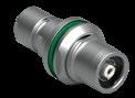
BULKHEAD FEEDTHROUGH WDE
Type "AZ" is the standard version of the WDE. The flange side accepts an "A" type plug, and the threaded side accepts a "Z" type plug.
The "ZA" version of the WDE accepts a type "Z" plug at the flange side and accepts a type "A" plug at the threaded end.
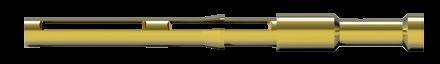
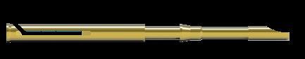
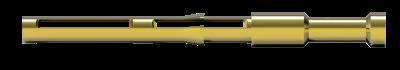
Fischer Connectors’ contacts are highly reliable and are guaranteed up to 10,000 mating cycles.
All standard brass and bronze contacts for use in the Core Series Brass are screw machined, and are gold plated over a nickel underplate.
Most connectors are available with solder, crimp or PCB contacts, and each type is optimized for a particular application.
Most versatile
Pre-installed contacts
Qualified assemblers required
Can be produced with any type of contact block material and accept a wide range of wire sizes.
Contacts are pre-installed in the insulator block, and the wires can be terminated with any appropriately sized soldering iron.
May require operators who are qualified in specialized soldering techniques.
PCB or Flex circuit mount
Reduced pin diameter
Wave soldering

Designed to be mounted directly onto a PCB or flex circuit; can be used in wave soldering operations for faster production assembly.
Preferred for high rates of data transmission due to the low distance to the board that their integration allows. This helps reducing signal interferences.
PCB pins are generally used on rear mounted panel connectors.
Selectively annealed area
Special tools required
Limited range of wire sizes
Each contact has a selectively annealed area which is deformed during assembly by specialized tooling to assure proper termination of the wire to the contact.
Commonly used for field termination or repair, as no soldering process is required.
Not available for sealed or hermetic connectors.
See section Tooling, section B 6-21, for description of Crimping Tool and Positioner. Please refer to www.fischerconnectors.com/technical for detailed information and assembly instructions.
= Standard = Option
102
[1]
[19/40]
[1]
1) Stranding values are in brackets.
2) Testing may be required. For a given AWG, the diameter of some stranded conductor designs could exceptionally be larger than the hole diameter of the barrel.
3) Current per contact at 40°C temperature rise measured on the basic curve according to IEC 60512-5-2-5b. For the max. operating current a reduction factor must be used and limitations due to the size of the wires and the permissible upper temperature limit of the materials employed must be taken into account. See page A-12 for details.
4) Recommended operating voltage at sea level measured according to IEC 60664-1.
5) Measured with S plug and D receptacle. Please contact us for ratings for WSO right-angle plugs and WDE bulkhead feedthroughs.
6) Plug with crimp contacts must be used with unshielded clamps only. See page B 2-43.
7) Only available for A polarity plugs.
8) Solder contact version of DBPLE/DBPLU with ground contact: Ground contact for wire size: max 0.79mm AWG 21 [1] / AWG 22 [7/30].
9) Layout dedicated to SPE data protocol 1 Gbit/s
103 A 062 Z 12
1) Stranding values are in brackets.
2) For a given AWG, the diameter of some stranded conductor designs could exceptionally be larger than the hole diameter of the barrel. Testing may be required.
3) Current per contact at 40°C temperature rise measured on the basic curve according to IEC 60512-5-2-5b. For the max. operating current a reduction factor must be used and limitations due to the size of the wires and the permissible upper temperature limit of the materials employed must be taken into account. See page A-12 for details.
4) Recommended operating voltage at sea level measured according to IEC 60664-1.
5) Measured with S plug and D receptacle. Please contact us for rating for WSO right-angle plugs and WDE bulkhead feedthroughs.
6) Not available in sealed version.
7) The 3 power contacts 0.9 mm as well as contact 0.5 mm No. 1 are positioned to make contact first & break last.
1) Stranding values are in brackets.
2) For a given AWG, the diameter of some stranded conductor designs could exceptionally be larger than the hole diameter of the barrel. Testing may be required.
3) Current per contact at 40°C temperature rise measured on the basic curve according to IEC 60512-5-2-5b. For the max. operating current a reduction factor must be used and limitations due to the size of the wires and the permissible upper temperature limit of the materials employed must be taken into account. See page A-12 for details.
4) Recommended operating voltage at sea level measured according to IEC 60664-1.
5) Measured with S plug and D receptacle. Please contact us for rating for WSO right-angle plugs and WDE bulkhead feedthroughs.
6) Not available in sealed version.
1) Stranding values are in brackets.
2) For a given AWG, the diameter of some stranded conductor designs could exceptionally be larger than the hole diameter of the barrel. Testing may be required.
3) Current per contact at 40°C temperature rise measured on the basic curve according to IEC 60512-5-2-5b. For the max. operating current a reduction factor must be used and limitations due to the size of the wires and the permissible upper temperature limit of the materials employed must be taken into account. See page A-12 for details.
4) Recommended operating voltage at sea level measured according to IEC 60664-1.
5) Measured with S plug and D receptacle. Please contact us for rating for WSO right-angle plugs and WDE bulkhead feedthroughs.
6) Test voltages between the contacts with the shortest distance.
1) Stranding values are in brackets.
2) For a given AWG, the diameter of some stranded conductor designs could exceptionally be larger than the hole diameter of the barrel. Testing may be required.
3) Current per contact at 40°C temperature rise measured on the basic curve according to IEC 60512-5-2-5b. For the max. operating current a reduction factor must be used and limitations due to the size of the wires and the permissible upper temperature limit of the materials employed must be taken into account. See page A-12 for details.
4) Recommended operating voltage at sea level measured according to IEC 60664-1.
5) Measured with S plug and D receptacle. Please contact us for rating for WSO right-angle plugs and WDE bulkhead feedthroughs.
6) Not available in sealed version.
7) Contact No. 1 is positioned to make contact first & break last. Only available in sealed version.
[1]
1) Stranding values are in brackets.
2) For a given AWG, the diameter of some stranded conductor designs could exceptionally be larger than the hole diameter of the barrel. Testing may be required.
3) Current per contact at 40°C temperature rise measured on the basic curve according to IEC 60512-5-2-5b. For the max. operating current a reduction factor must be used and limitations due to the size of the wires and the permissible upper temperature limit of the materials employed must be taken into account. See page A-12 for details.
4) Recommended operating voltage at sea level measured according to IEC 60664-1.
5) Measured with S plug and D receptacle. Please contact us for rating for WSO right-angle plugs and WDE bulkhead feedthroughs.
6) Solder and PCB contact types available only for DBPU and DBPLU receptacles. Crimp contact type available only for plugs.
7) Layout dedicated to UHD-Video 18 Gbit/s. Only available in sealed version.
8) The 3 power contacts 0.9 mm as well as contact 0.5 mm No. 1 are positioned to make contact first & break last. Only available in sealed version.
9) Current of 1.8 A at maximum temperature rise of 30 °C according to UHD specifications.
1) Stranding values are in brackets.
2) For a given AWG, the diameter of some stranded conductor designs could exceptionally be larger than the hole diameter of the barrel. Testing may be required.
3) Current per contact at 40°C temperature rise measured on the basic curve according to IEC 60512-5-2-5b. For the max. operating current a reduction factor must be used and limitations due to the size of the wires and the permissible upper temperature limit of the materials employed must be taken into account. See page A-12 for details.
4) Recommended operating voltage at sea level measured according to IEC 60664-1.
5) Contact dia. 2.0 is positioned to make contact first and break last.
6) Measured with S plug and D receptacle. Please contact us for rating for WSO right-angle
= Standard = Option
1) Stranding values are in brackets.
2) For a given AWG, the diameter of some stranded conductor designs could exceptionally be larger than the hole diameter of the barrel. Testing may be required.
3) Current per contact at 40°C temperature rise measured on the basic curve according to IEC 60512-5-2-5b. For the max. operating current a reduction factor must be used and limitations due to the size of the wires and the permissible upper temperature limit of the materials employed must be taken into account. See page A-12 for details.
4) Recommended operating voltage at sea level measured according to IEC 60664-1.
5) Contacts dia. 1.3 are positioned to make contact first and break last.
6) Contacts dia. 1.6 are positioned to make contact first and break last.
7) Inverted polarity: female contacts on plug/male contact on receptacle.
8) Measured with S plug and D receptacle. Please contact us for rating for WSO right-angle plugs and WDE bulkhead feedthroughs.
All dimensions and images shown are in millimeters and are for reference only.
1) Stranding values are in brackets.
2) For a given AWG, the diameter of some stranded conductor designs could exceptionally be larger than the hole diameter of the barrel. Testing may be required.
3)Current per contact at 40°C temperature rise measured on the basic curve according to IEC 60512-5-2-5b. For the max. operating current a reduction factor must be used and limitations due to the size of the wires and the permissible upper temperature limit of the materials employed must be taken into account. See page A-12 for details.
4) Recommended operating voltage at sea level measured according to IEC 60664-1.
5) The contact solder cups are specially insulated.
6) Contact Number 1 is positioned to make contact first and break last.
7) Measured with S plug and D receptacle. Please contact us for rating for WDE bulkhead feedthroughs.
[1]
AWG21 [1] AWG22 [7/30]
ø0.88mm AWG20 [1] AWG22 [19/34]
1) Stranding values are in brackets.
2) For a given AWG, the diameter of some stranded conductor designs could exceptionally be larger than the hole diameter of the barrel. Testing may be required.
3) Current per contact at 40°C temperature rise measured on the basic curve according to IEC 60512-5-2-5b. For the max. operating current a reduction factor must be used and limitations due to the size of the wires and the permissible upper temperature limit of the materials employed must be taken into account. See page A-12 for details.
4) Recommended operating voltage at sea level measured according to IEC 60664-1.
5) Measured with S plug and D receptacle. Please contact us for rating for WDE bulkhead feedthroughs.
Housing colors
Cable bend reliefs and clamp nut types
Cable bend relief part numbering
B 2-39
B 2-39
B 2-41
All the body styles of our Core Series Brass Product Line are available in two colors:
A cable bend relief is a useful accessory for connectors mounted with cable clamp sets (S/SC; SOV; SA; SV; WSO; K/KE; DK; DKE; DBKE).
Natural chrome connector housing with red guide mark.
Non reflective black chrome housing with white guide mark.
Guide mark is standard for Multipole Low and High Voltage, Mixed Multipole and Mixed Coax connectors.
Color-coding is achieved by using accessories:
Cable bend reliefs for cable connectors.
Washers for panel receptacles.
It helps to:
Reduce bending stress on the cable and inner wires, enhancing durability
Color-code your connectors for easy identification.
Cable bend reliefs require special clamp nuts, thus are linked with your selection of options.
1 Housing color Which housing color do you need ?
2 Contact block material Which contact block material do you need ?
3 Contact type Which contact type do you need ?
4 Keying code Which keying code do you need ?
1) Crimp contacts are not an option for sealed or hermetic connectors.
DESIGN AND ACCESSORIES
Applicable for Last digit Description
Front mounted :
Applicable Last mounted DBEU
-
/ E -
- SFU/E 0 Standard : solder contacts
SFU / E
Rear mounted :
DBP - DBPU/E - DBPLU/EDGP - SFPU/E
9 With PCB (Printed Circuit Board) contacts instead of solder contacts
0 Standard : PCB (Printed Circuit Board) contacts
DBPU / E - DBPLU / ESFPU E Board)
9 With solder contacts instead of PCB (Printed Circuit Board) contacts
Options are available on request, please contact us.
Applicable for Extensions Description Receptacles
Nickel plated body with bright finish
EPDM interface O-ring
Ground tag if solder contact or ground pin if PCB contact B Black nut D Decorative slotted nut F Decorative nut (with 2 flats)
CABLE BEND RELIEF
Do you need a cable bend relief, and if yes which color ?
Applicable for Last digit Description
Cable mounted plugs & receptacles using cable clamp sets except SS / SSC - KS / KSE
0 Clamp nut without bend relief
1 Clamp nut with white bend relief
2 Clamp nut with black bend relief
3 Clamp nut with green bend relief
4 Clamp nut with blue bend relief
5 Clamp nut with yellow bend relief
6 Clamp nut with red bend relief
7 Clamp nut with grey bend relief
PLUGS
S 102 A056 -130+
Natural chrome housing color with PEEK contact block, solder contacts, keying code 1, clamp nut without bend relief and without cable clamp set (To be ordered separately)
S 102 A056 -232+
Natural chrome housing color with PEEK contact block, solder contacts, keying code 2, clamp nut with black bend relief, without cable clamp set
SS 102 A056 -260
Black chrome housing color with PEEK contact block, crimp contacts, keying code 2
D 102 A056 -130
Natural chrome housing color with PEEK contact block, solder contacts, keying code 1
D 102 A056 -260
Black chrome housing color with PEEK contact block, crimp contacts, keying code 2
DBPU 102 A056 -130G
Natural chrome housing color with PEEK contact block, PCB contacts, keying code 1 and ground pin
DBPU 102 A056 -130NBE
Nickel plated body with PEEK contact block, PCB contacts, keying code 1, with black nut and EPDM interface O-ring
dimensions and images shown are in millimeters and are for reference only.
S/SC; SOV; SA; SV; K/KE; DK; DKE & DKBE; BODY STYLES
103, 1031, 104 & 105 Size
2-51
To guarantee excellent cable retention and strain relief, Fischer Connectors provides robust and high quality cable clamp sets :
Collet style clamp system retaining cable over large jacket surface area.
Protection of small diameters and delicate conductors.
Can be combined with cable bend reliefs for optimal performance.
Cable clamp sets are suitable for all cable mounted connectors, except SS/SSC and KS/KSE.
Fischer Connectors offers three types of cable clamps sets. The table below will help you select the one corresponding to your needs.
Do you need the interface between the cable and the connector to be sealed ?
Do you need the connector to be terminated to the cable shield ?
Cable clamp set
S - Shielded
U - Unshielded
E - Environmental
For 106 and 107 connector sizes, only S and E cable clamp sets are available.
Below cable clamp sets should be ordered separately
S 102 A056-130+
Examples connector ordering line
Below cable clamp sets are included with connector
high voltage
Shielded (S) or Environmental (E) cable clamp set diameter should be added to the connector part number separated by ø.
Examples for S - Shielded clamp sets
Clamp set ordering line For E - Environmental clamp sets
See following pages for cable clamp sets set selection.
All dimensions and images shown are in millimeters and are for reference only.
See following pages for S or E cable clamp sets set selection.
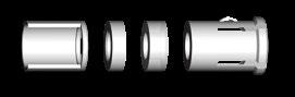
Shielded cable clamp with sleeve and clamp.
UNSHIELDED
Unshielded, one-piece cable clamp.
Environmentally sealed clamp for use with shielded or unshielded cables.
1) For ordering information see page B 2-43.
SHIELDED
Shielded cable clamp with with sleeve, washer and clamp.
Sleeve
Unshielded, one-piece cable clamp.
Environmentally sealed clamp for use with shielded or unshielded cables.
Clamp Sleeve
1) For ordering information see page B 2-43.
All dimensions and images shown are in millimeters and are for reference only.
Shielded cable clamp with with sleeve, washer and clamp.
Unshielded, one-piece cable clamp.
Environmentally sealed clamp for use with shielded or unshielded cables.
1) For ordering information see page B 2-43.
Clamp Sleeve
Seal Washer Ring Clamp Sleeve
Shielded cable clamp with with sleeve, spacer and clamp. U UNSHIELDED
Unshielded, one-piece cable clamp.
Environmentally sealed clamp for use with shielded or unshielded cables.
1) For ordering information see page B 2-43.
All dimensions and images shown are in millimeters and are for reference only.
Shielded cable clamp with sleeve, spacer and clamp.
UNSHIELDED
Unshielded, one-piece cable clamp.
Environmentally sealed clamp for use with shielded or unshielded cables.
1) For ordering information see page B 2-43.
Clamp Sleeve
Spacer
Shielded cable clamp with sleeve, spacer and clamp.

8.2
Shielded cable clamps with washers and sleeves.
Environmentally sealed clamp for use with shielded or unshielded cables.
1) For ordering information see page B 2-43.
Shielded cable clamp with sleeve, spacer and clamp.
Environmentally sealed clamp for use with shielded or unshielded cables.
For ordering information see page B 2-43.


2.2 - 2.7 2.7 E3 1031.12/2.7 E3 1031.13/2.7
2.7 - 3.2 3.2 E3 1031.12/3.2 E3 1031.13/3.2
3.2 - 3.7 3.7 E3 1031.12/3.7 E3 1031.13/3.7
3.7 - 4.2 4.2 E3 1031.12/4.2 E3 1031.13/4.2
4.2 - 4.7 4.7 E3 1031.12/4.7 E3 1031.13/4.7
4.7 - 5.2 5.2 E3 1031.12/5.2 E3 1031.13/5.2
5.2 - 5.7 5.7 E3 1031.12/5.7 E3 1031.13/5.7
5.7 - 6.2 6.2 E3 1031.12/6.2 E3 1031.13/6.2
6.2 - 6.7 6.7 E3 1031.12/6.7 E3 1031.13/6.7 6.7 - 7.2 7.2 E3 1031.12/7.2 -
1) For ordering information see page B 2-43.
All dimensions and images shown are in millimeters and are for reference only.
Body
Protection
Locking system
Unsealed (IP50)
Friction
Push-pull
Quick-release
Lanyard
Tamperproof
Contacts
Housing color
Sealing categories, page A-6
Locking systems, page A-5
Electrical & contact configurations, page B 2-57 Solder
chrome
Design Shortened body
Cabling
Options, page B 2-35
Body styles, chapter B 1-2 Right-angle
Cable clamp sets
Overmoldable
Heat shrinkable
Accessories Cable bend reliefs
Sealing
Insulating cable clamps, B 2-59
Accessories, section B 6-2
Dimensions, page B 2-52
1) Clamp sets for sealed or shielded connectors are available on request.
Torque [Nm] are recommended values that may be influenced by the characteristics of the cable jacket. Tests have to be made to evaluate the exact values. To secure the cable clamp nut, we recommend the use of thread locking adhesive.
dimensions and images shown are in millimeters and are for reference only.

Body
Protection
Unsealed (IP50)
Sealed up to IP681)
Hermetic1)
Crimp
Contacts
Housing
References
Sealing categories, page A-6
Electrical & contact configurations, page B 2-57 Solder PCB
Options, page B 2-35
Design
Assembly
Right-angle
Flush
Front-projecting
Bulkhead feedthrough
Front-mounting
Rear-mounting
Sealing caps
Spacers
Accessories
Color-coded washers
Grounding washers
Locking washers Size
1) Please contact us.
Body styles, chapter B 1-3
Accessories, section B 6-2
Technical dimensions, page B 2-55
BODY STYLE
Receptacles of 106 and 107 Sizes are supplied with slotted nuts.
For nut dimensions see Accessories section B 6-2.
For wrenches see section Tooling section, page B 6-19. Torque [Nm] are recommended values that may be influenced by the quality of the panel surface under the nut. Tests have to be made to evaluate the exact values.
Other connector styles and contact configurations are available on request.
BODY STYLE
All dimensions and images shown are in millimeters and are for reference only.
For Multipole High Voltage connectors, it is essential to pay attention to the differences between type "A" and "Z".
Type "A" standard polarity
The contacts of the receptacle are recessed to reduce the possibility of electric shock in the unmated position.
This version should be used when the voltage is sourced from the receptacle.
Type "Z" inverted polarity
The contacts of the plug are recessed to reduce the possibility of electric shock in the unmated position.
This version should be used when the voltage is sourced from the plug.
Protected contacts are usually female contacts recessed in the insulator.
For Multipole High Voltage connectors, however, it is safer to recess the male contacts. In these cases, the plug type "A" is equipped with female contacts and the receptacle with protected male contacts.
dimensions and images shown are in millimeters and are for reference only.
1) Current per contact at 40°C temperature rise measured on the basic curve according to IEC 60512-5-2-5b. For the max. operating current a reduction factor must be used and limitations due to the size of the wires and the permissible upper temperature limit of the materials employed must be taken into account. See page A-12 for details.
2) For clamp sets selection see page B 2-50.
3) See Tooling section, page B 6-24, for insertion tool of contacts.
4) Measured with S plug and D receptacle.
5) Only PTFE insulator and "A" polarity for DEE and DBEE body styles.
6) Only available in D body style with "A" polarity.
7) Only available in D body style. Contact us for other body style additional information.
8) For DEE "A" polarity, the contact block is composed of two parts : one is PEEK and the second one is PTFE.
9) DBEE only available with PEEK insulator and "A" polarity.
10) Only available "A" polarity.
Multipole High Voltage connectors, as well as Mixed High Voltage and Mixed Coax connectors, are equipped with POM (Delrin®) collet type cable clamps.
These insulated one-piece clamps are fitted for optimal High-Voltage ratings.
Material
POM (Polyoxymethylene) Delrin®
Insulating cable clamp set is included with connector
Multipole high voltage Mixed high voltage Mixed coax
Insulating clamp set ø should be added to the connector part number separated by ø (select the collet ø according to the cable clamping range) and followed by- UI (Unshielded Insulated). Example S 104 A062-130 ø 6.6-UI
104 size 4 pole high voltage S plug with insulating cable clamp set allowing cable diameter included between 4.7 & 6.6 mm
Insulating cable clamps set. Not available. See page B2-50
Insulating cable clamps set, not available. See page B 2-50.
All dimensions and images shown are in millimeters and are for reference only.
Protection
Unsealed (IP50)
Sealed up to IP68
References to detailed information
Sealing categories, page A-6
Locking system
Tamperproof
Contacts
Housing
Design
Locking systems, page A-5
Electrical & contact configurations, page B 3-22
Options, page B 3-26
Body styles, page B 1-2
Cable clamp set included in product except for WSO, page B 2-39
Accessories, page B 6-2
Technical dimensions, page B 3-4
S/SE/SC/SCE
Torque [Nm] are recommended values that may be influenced by the characteristics of the cable jacket. Tests have to be made to evaluate the exact values. To secure the cable clamp nut, we recommend the use of thread locking adhesive.
SA/SAE
BODY STYLE
SV/SVE
BODY STYLE
Torque [Nm] are recommended values that may be influenced by the characteristics of the cable jacket. Tests must be conducted to evaluate the exact values. To secure the cable clamp nut, we recommend the use of thread locking adhesive.
All dimensions and images shown are in millimeters and are for reference only.
Remark: Layout 102 A017, 104 A002, 104 A060, 105 A090, 105 Z090 are not available in WSO body style.
Body
Protection
Unsealed (IP50)
Sealed up to IP68
Contacts Crimp
Solder
Natural chrome
Housing
Black chrome
Shortened body
Cable clamp sets
Cabling
Overmoldable
Heat shrinkable
Cable bend reliefs
Accessories
Protective sleeves
Sealing caps
References to detailed information
Sealing categories, page A-6
Electrical & contact configurations, page B 3-22
Options, page B 3-26
Body styles, page B 1-3
Cable clamp set included in product, pages B2-39
Accessories, page B 6-2
Technical dimensions, page B 3-8
For more information visit :
1) Environmental cable clamp set included.
Recommended values that may be influenced by the characteristics of the cable jacket. Tests must be conducted to evaluate the exact values. To secure the cable clamp nut, we recommend the use of thread locking adhesive.
Protection
Contacts
Housing color
Design
Assembly
Unsealed (IP50)
Sealed up to IP68
Hermetic
Crimp
Solder
PCB
Natural chrome
Black chrome
Right-angle
Flush
Front projecting
Bulkhead feedthrough
Front-mounting
Rear-mounting
Sealing caps
Spacers
Accessories
Color-coded washers
Grounding washers
Locking washers
Size
References to detailed information
Sealing categories, page A-6
Electrical & contact configurations, page B 3-22
Options, page B 3-26
Body style selection, page B 1-3
Accessories, page B 6-2
Technical dimensions, page B 3-11
For more information visit: www.fischerconnectors. com/technical
Unsealed (IP50)
Protection
Sealed up to IP68
Hermetic
Contacts
Design
Assembly
Right-angle
Flush
Front projecting
Bulkhead feedthrough
Front-mounting
Rear-mounting
Sealing caps
Spacers
Accessories
Color-coded washers
Grounding washers
Locking washers
References to detailed information
Sealing categories, page A-6
Electrical & contact configurations, page B 3-22
Options, page B 3-26
Body styles, page B 1-3
Accessories, page B 6-2
Technical dimensions, page B 3-13
For more information visit: www.fischerconnectors. com/technical
Torque [Nm] are recommended values that may be influenced by the quality of the panel surface under the nut. Tests must be conducted to evaluate the exact values.
All dimensions and images shown are in millimeters and are for reference only.
BODY STYLE
DBEU/DBEE BODY STYLES
1) Assembly tool for decorative slotted nut, see Tooling section, page B 6-20 for details.
Torque [Nm] are recommended values that may be influenced by the quality of the panel surface under the nut.
Tests must be conducted to evaluate the exact values.
All dimensions and images shown are in millimeters and are for reference only.
DBPLU/DBPLE
1) Assembly tool for decorative slotted nut, see Tooling section, page B 6-20, for details.
WDE FOR 102, 103 & 104 SIZE
BODY STYLE
WDE FOR 105 SIZE
BODY STYLE
The bulkhead feedthrough connector allows the passing of electrical signals and power through a panel via two cable plugs.
The "AZ" version of the feedthrough accepts a type "A" plug on the flange side and a type "Z" plug on the threaded end, which is typically oriented toward the interior of the chassis. In the version "ZA", the connections "A" and "Z" are inverted, see "A/Z Polarity" on page A-10.
Dimension "B max" specifies the maximum panel thickness.
All dimensions and images shown are in millimeters and are for reference only.
Protection
Unsealed (IP50)
Sealed up to IP68
Hermetic
Crimp
Contacts
Solder
PCB
Housing color
Assembly
Accessories
Sealing categories, page A-6
Electrical & contact configurations, page B 3-22
chrome Options, page B 3-26
Front-mounting Body styles, page B 1-2
Rear-mounting
Sealing caps
Spacers
Color-coded washers
Insulating washers
Grounding washers
Locking washers
dimensions, page B 3-17
Torque [Nm] are recommended values that may be influenced by the quality of the panel surface under the nut. Tests must be conducted to evaluate the exact values.
All dimensions and images shown are in millimeters and are for reference only.
Protection
Unsealed (IP50)
Sealed up to IP68
Links to detailed information
Sealing categories, page A-6
Contacts Crimp Electrical & contact configurations, page B 3-22
Housing color
Design
Assembly
Solder
chrome
chrome
Flush
Front-projecting
Panel-mounted
Front-mounting
Rear-mounting
Cable mounted
Cable clamp sets
Cable bend reliefs
Sealing caps
Spacers
Accessories
Color-coded washers
Insulating washers
Grounding washers
Locking washers
1) Environmental cable clamp set
Options, page B 3-26
Body styles, page B 1-3
Cable clamp set included in product, pages B2-39
Accessories, page B 6-2
Technical dimensions, page B 3-20
BODY STYLE
Torque [Nm] are recommended values that may be influenced by the characteristics of the cable jacket. Tests have to be made to evaluate the exact values. To secure the cable clamp nut, we recommend the use of thread locking adhesive.
1) Cable assembly operation possible only after housing mounted on panel
DKE FOR 102 & 103 SIZE
BODY STYLES
DKE FOR 104 & 105 SIZE
BODY STYLES
1) See list of recommended cables on page B 3-24.
2) Current per contact at 40°C temperature rise measured on the basic curve according to IEC 60512-5-2-5b. For the max. operating current a reduction
wires and the permissible upper temperature limit of the materials employed must be taken into account. See page A-12 for details.
3) Measured with S plug and D receptacle. Please contact us for ratings for WSO right-angle plugs and WDE bulkhead feedthroughs.
4) PEEK is mainly used for hermetic connectors.
5) Solder contact version of DBPLE/DBPLU with ground contact: Ground contact for wire size: max 0.79mm AWG 21 [1] / AWG 22 [7/30].
must
1) See list of recommended cables on page B 3-24.
2) Current per contact at 40°C temperature rise measured on the basic curve according to IEC 60512-5-2-5b. For the max. operating current a reduction factor must be used and limitations due to the size of the wires and the permissible upper temperature limit of the materials employed must be taken into account. See page A-12 for details.
3) Measured with S plug and D receptacle. Please contact us for ratings for WSO right-angle plugs and WDE bulkhead feedthroughs.
4) PEEK is mainly used for hermetic connectors.
5) Solder contact version of DBPLE/DBPLU with ground contact: Ground contact for wire size: max 0.79mm / AWG 21 [1] / AWG 22 [7/30]. = Standard = Option
3
2
1
RG-174A/U
RG-174/U
RG-178B/U
RG-188A/U
RG-196A/U
RG-316/U
RG-179B/U
5
4
1 Place for notes 1 Gr.
1) Insulated, stranded wires with screen and jacket, standardized by the German VDE 0812, for low frequency applications when no defined impedance is required.
2) Insulated, highly flexible stranded wires with screen and jacket, for low frequency applications when no defined impedance is required.
Legend
Cu Plain copper wire FEP Fluorethylenepropylene CSM Hypalon® (DuPont)
CuAg Silver plated copper wire FPE Foam polyethylene
CuSn Tin plated copper wire PE Polyethylene
StCu Copper-clad steel wire PTFE Polytetrafluorethylene
StCuAg Copper-clad steel wire, silver plated PVC Polyvinyl chloride
7 RG-212/U
RG-222/U
8 RG-115A/U
RG-214/U
RG-217/U
RG-280/U
RG-12A/U RG-34B/U
RG-403/U Triaxal
RG-178 Type Triax
SUHNER G 02332 Triaxial
12 BELDEN 9222 RG-58 Type Triax
All dimensions and images shown are in millimeters and are for reference only.
2. screen and jacket : 2. screen and jacket : 2. screen and jacket : 2. screen and jacket :
Solder contacts
Solder contacts Applicable for Extensions Description
Other options are available on request, please contact us.
Plugs
SV 103 A002-600 Ø6.7
Natural chrome housing color with PTFE contact block, solder contacts and cable clamp set (diameter 6.7 mm)
S 104 A060-600 Ø3.4 - UI
Natural chrome housing color with PTFE contact block, solder contacts and insulating clamp set (diameter 3.4 mm)
DBPLE 102 A002 - 709EGD
Black chrome housing color with PTFE contact block, solder contacts, EPDM interface O-ring, ground tag and decorative slotted nut
DKBE 103 A026 - 600 Ø6.2E
Natural chrome housing color with PTFE contact block, solder contacts, cable clamp set (diameter 6.2 mm) and EPDM interface O-ring
All dimensions and images shown are in millimeters and are for reference only.
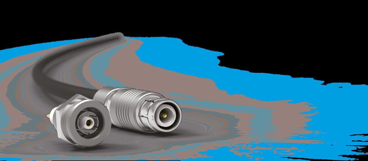
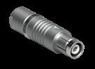
Body style
Protection
Locking system
Unsealed (IP50)
Sealed up to IP68
None
Push-pull
Quick-release
Lanyard
Tamperproof
Crimp
Contacts
Housing color
Design
Cabling
Solder
Natural chrome
Black chrome
Shortened body
Right-angle
Cable clamp sets
Overmoldable
Heat shrinkable
Accessories
References to detailed information
Sealing categories, page A-6
Locking systems, page A-5
Electrical & contact
page B 3-34
Options, page B 3-26
Body styles, page B 1-2
Cable clamp set included in product, page B 2-39
Cable bend reliefs Accessories, page B 6-2
Sealing
Size
1) Environmental cable clamp set included.
dimensions, page B 3-30 For
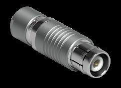
1) Cable screen and jacket (e.g. RG-58) are retained by hex-crimp to the plug shell.
2) For improved safety, the center contact is further recessed than in the S 105 A049.
3) Two wrenches with an opening of 32 mm are required for SV/SVE 107 size.
4) For insertion of center contact which has to be assembled after wiring, we recommend tool TP00.000, as shown on the
page B 6-24.
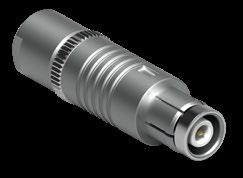
Suitable Coax cables are indicated in the column "Cable Group" in Electrical & Contact specifications. The cable specifications are listed on page B 3-24. If required, we will supply adapter sleeves which must be placed over the cable dielectric during assembly in order to guarantee proper performance. For cable clamps sets see page B 2-39. For non-sealed Coax connectors, the collet diameter has to be selected from the tables of type "S-Shielded", and for sealed Coax connectors from the tables of type "Environmental".
Torque [Nm] are recommended values that may be influenced by the characteristics of the cable jacket. Tests have to be made to evaluate the exact values. To secure the cable clamp nut, we recommend the use of thread locking adhesive.
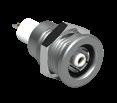
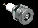
Body style D DEE
Unsealed (IP50)
Protection
Sealed up to IP68
Hermetic
Crimp
Contacts
Housing color
Solder
PCB
Natural chrome
Black chrome
Right-angle
Flush
Design
Assembly
Accessories
Front-projecting
Bulkhead feedthrough
Front-mounting
Rear-mounting
Sealing caps
Spacers
Color-coded washers
Grounding washers
Locking washers
102 Size
Size
References to detailed information
Sealing categories, page A-6
Electrical & contact configurations, page B 3-34
Options, page B 3-26
Body styles, page B 1-3
Accessories, page B 6-2
Technical dimensions, page B 3-32
For more information visit: www.fischerconnectors.com/technical
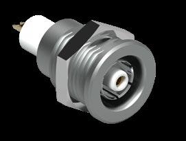
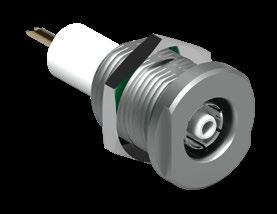
1) Non standard dimension of panel cut-out: ø11.1
2) Also available with an optional micro switch.
Receptacles of 106 and 107 sizes are supplied with slotted nuts. For wrenches see Tooling section page B 6-19.
Torque [Nm] are recommended values that may be influenced by the quality of the panel surface. Tests have to be made to evaluate the exact values.
All dimensions and images shown are in millimeters and are for reference only.
1) See list of recommended cables on page B 3-24.
2) Current per contact at 40°C temperature rise measured on the basic curve according to IEC 605125-2-5b. For the max. operating current a reduction factor must be used and limitations due to the size of the wires and the permissible upper temperature limit of the materials employed must be taken into account. See page A-12 for details.
3) Plug: center contact-crimp Outer contact-crimp ferrule. Receptacle: center contact-solder Outer contact-washer with solder tag.
4) Plug contains additionally recessed contacts.
5) See Tooling section, page B 6-23, for insertion tool of contact.
6) Measured with S plug and D receptacle.
7) PEEK is mainly used for hermetic connectors.
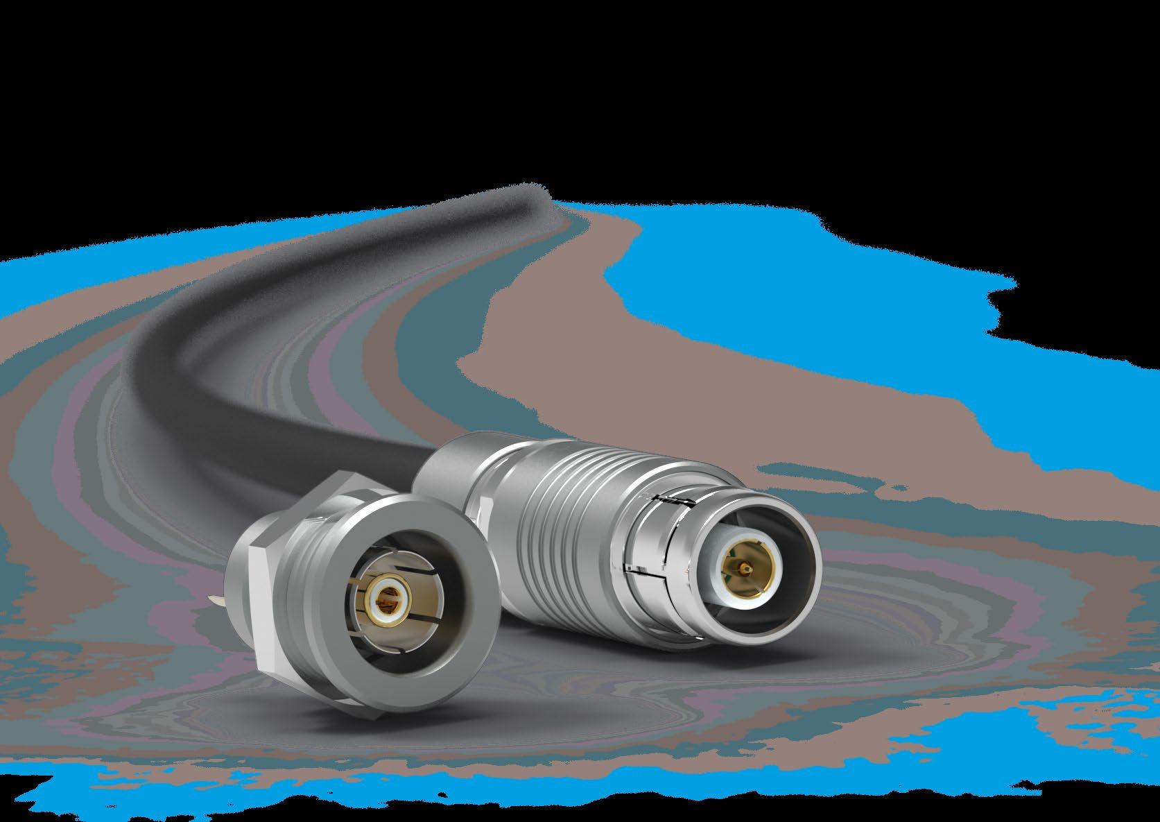
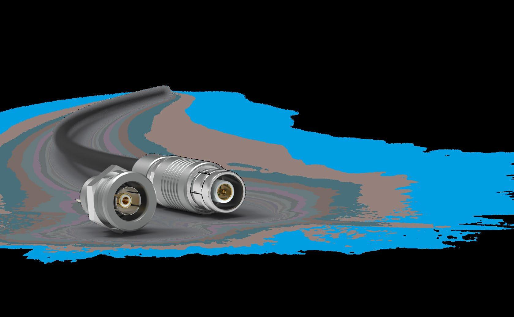
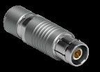

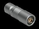

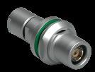
Sealed
Locking
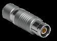
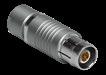
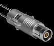
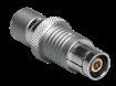
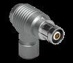
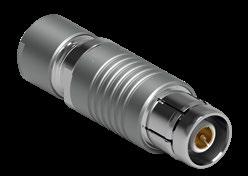
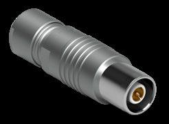
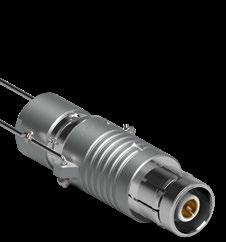
Torque [Nm] are recommended values that may be influenced by the characteristics of the cable jacket. Tests must be conducted to evaluate the exact values.
To secure the cable clamp nut, we recommend the use of thread locking adhesive.
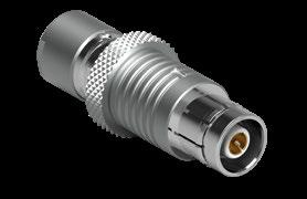
All dimensions and images shown are in millimeters and are for reference only.
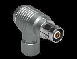
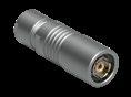
Body style
Protection
Contacts
Housing
Unsealed (IP50)
Sealed up to IP68
Crimp
Solder
Natural chrome
Black chrome
Shortened body
Cable clamp sets
Cabling
Overmoldable
Heat shrinkable
Cable bend reliefs
Accessories
Protective sleeves
Sealing caps Size
References to detailed information
Sealing categories, page A-6
Electrical & contact configurations, page B 4-18
Options, page B 3-26
Cable clamp set, page B 2-39
Accessories, page B 6-2
Technical dimensions, page B 4-8
For more information visit: www.fischerconnectors.com/technical
K/KE
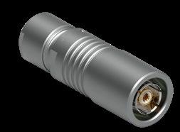
Torque [Nm] are recommended values that may be influenced by the characteristics of the cable jacket. Tests must be conducted to evaluate the exact values. To secure the cable clamp nut, we recommend the use of thread locking adhesive.
Protection


Unsealed (IP50)
Sealed up to IP68
Hermetic
Crimp
Contacts
Solder
PCB
Natural chrome
Housing color
Design
Assembly
Accessories
Sealing categories, page A-6
Electrical & contact configurations, page B 4-18
Options, page B 3-26 Black chrome
Right-angle
Flush
Front projecting
Bulkhead feedthrough
Front-mounting
Rear-mounting
Sealing caps
Spacers
Color-coded washers
Insulating washers
Grounding washers
Locking washers
Body styles, page B 1-3
Accessories, page B 6-2
Technical dimensions, page B 4-10
For more information visit:
BODY STYLE
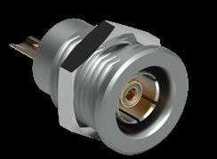
DEU/DEE BODY STYLES
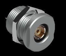
1)Not applicable for 102 A021.
PANEL MOUNTED
DB BODY STYLE
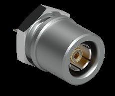
Torque [Nm] are recommended values that may be influenced by the quality of the panel surface. Tests must be conducted to evaluate the exact values.
DBEU/DBEE BODY STYLES
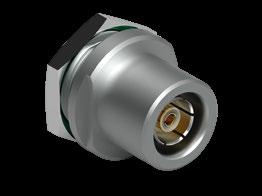
All dimensions and images shown are in millimeters and are for reference only.
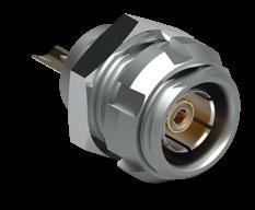


Body style
Protection
Contacts
Housing color
Assembly
Accessories
Unsealed (IP50)
Sealed up to IP68
Hermetic
Crimp
Solder
PCB
Natural chrome
Black chrome
Front-mounting
Rear-mounting
Sealing caps
Spacers
Color-coded washers
Insulating washers
Grounding washers
Locking washers Size
102 Size
References to detailed information
Sealing categories, page A-6
Electrical & contact configurations, page B 4-18
Options, page B 3-26
Body styles, page B 1-2
Accessories, page B 6-2
Technical dimensions, page B 4-14
For more information visit: www.fischerconnectors.com/technical
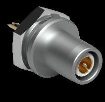
Torque [Nm] are recommended values that may be influenced by the quality of the panel surface. Tests must be conducted to evaluate the exact values.
SFU/SFE BODY STYLES
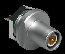
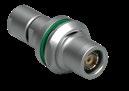
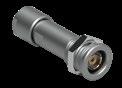
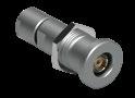
Body style
Protection
Contacts
Housing color
Design
Unsealed (IP50)
Sealed up to IP68
Crimp
Solder
Natural chrome
Black chrome
Flush
Front-projecting
Panel mounted
Front-mounting
Assembly
Rear-mounting
Cable mounted
Cable clamp sets
Cable bend reliefs
Sealing caps
Spacers
Accessories
Color-coded washers
Insulating washers
Grounding washers
Locking washers
102 Size
Size
dimensions and images shown are in millimeters and are for reference only.
Links to detailed information
Sealing categories, page A-6
Electrical & contact configurations, page B 4-18
Options, page B 3-26
Body styles, page B 1-3
Cable clamp sets, page B 2-39
Accessories, page B 6-2
Technical dimensions, page B 4-16
For more information visit:
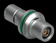
1) Cable assembly operation possible only after housing mounted on panel
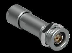
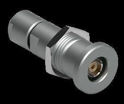
Torque [Nm] are recommended values that may be influenced by the characteristics of the cable jacket and the quality of the panel surface. Tests must be conducted to evaluate the exact values. To secure the cable clamp nut, we recommend the use of thread locking adhesive.
All dimensions and images shown are in millimeters and are for reference only.
1) See list of recommended cables on page B 3-24.
2) Current per contact at 40°C temperature rise measured on the basic curve according to IEC 60512-5-2-5b. For the max. operating current a reduction factor must be used and limitations due to the size of the wires and the permissible upper temperature limit of the materials employed must be taken into account. See page A-12 for details.
3) Measured with S plug and D receptacle. Please contact us for ratings for WSO right-angle plugs.
4) Inverted polarity: female contact on plug/male contact on receptacle. = Standard = Option
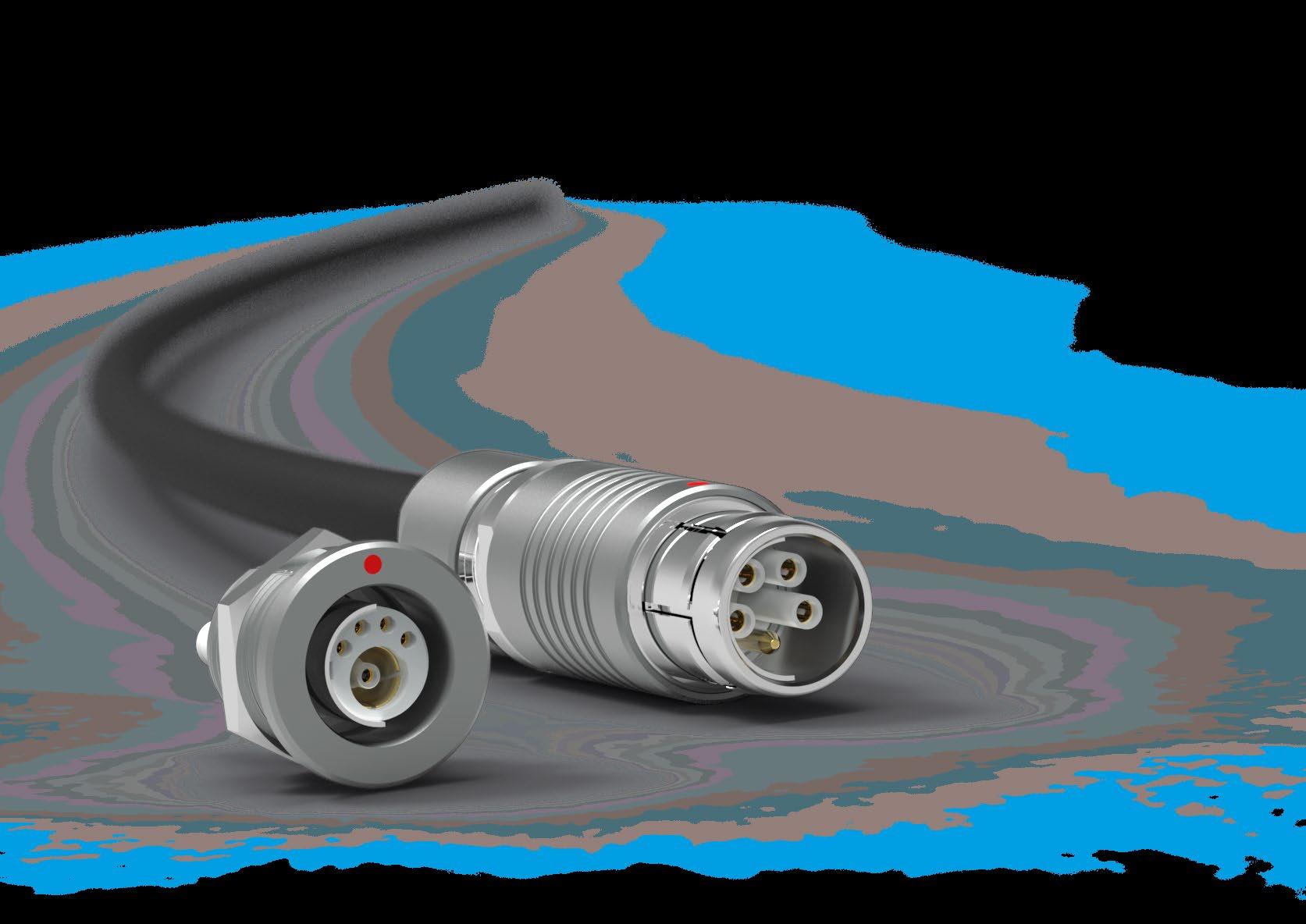
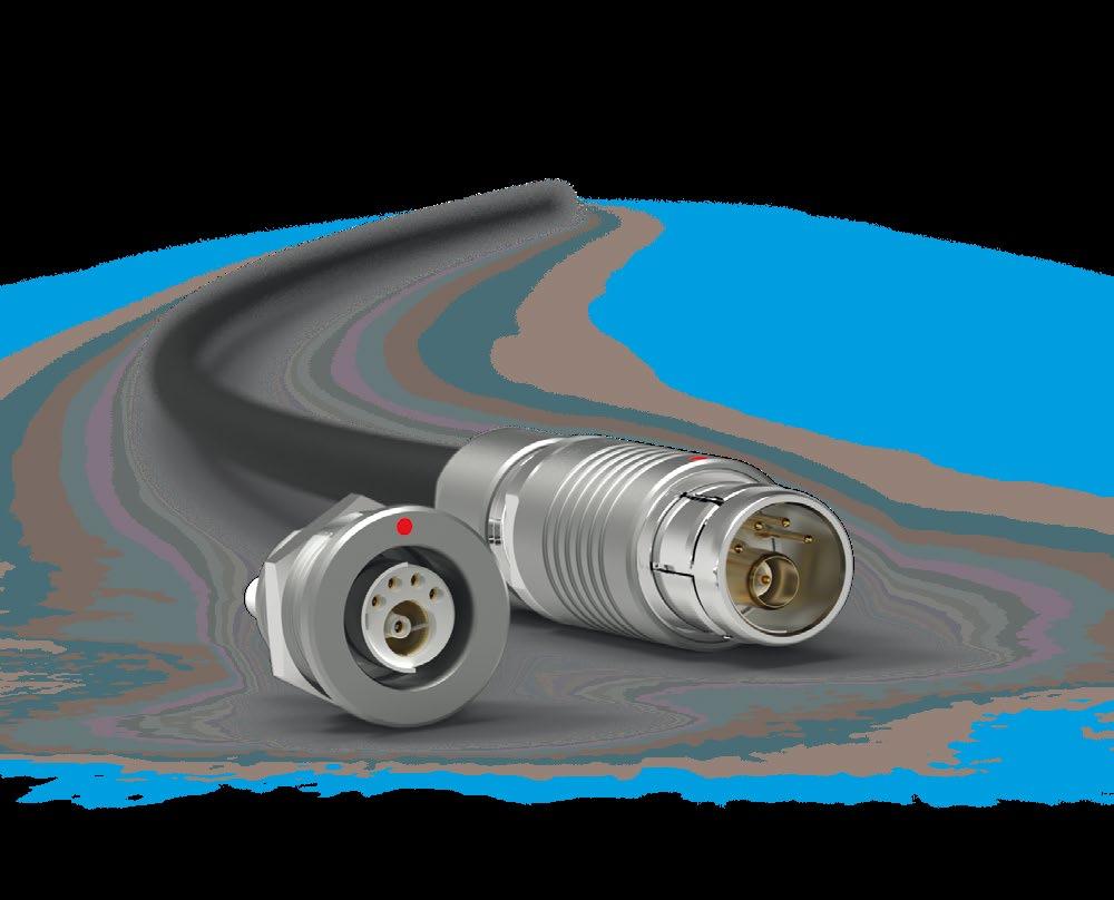
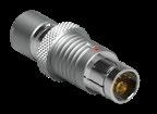
Protection Unsealed (IP50) Sealing
Sealed
Locking
Push-pull Quick-release
Lanyard
Tamperproof
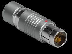
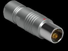
Torque [Nm] are recommended values that may be influenced by the characteristics of the cable jacket. Tests must be conducted to evaluate the exact values. To secure the cable clamp nut, we recommend the use of thread locking adhesive.
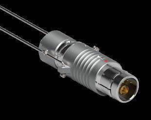
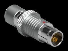
Protection
Contacts
Housing
Unsealed (IP50)
Sealed up to IP68
Crimp (coax)
Solder (others)
Natural chrome
Black chrome
Shortened body
Cable clamp sets
Cabling
Overmoldable
Heat shrinkable
Accessories Cable bend reliefs
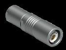
Sealing categories, page A-6
Electrical & contact configurations, page B5-16
Options, page B 3-26
Insulating cable clamp sets, page B 2-59
Accessories, page B 6-2
Technical dimensions, page B 5-7
For more information visit:
BODY STYLES
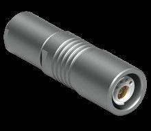
Torque [Nm] are recommended values that may be influenced by the characteristics of the cable jacket. Tests must be conducted to evaluate the exact values. To secure the cable clamp nut, we recommend the use of thread locking adhesive.
All dimensions and images shown are in millimeters and are for reference only.
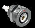
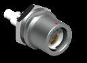
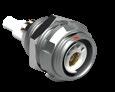
Protection
Contacts
Housing color
Unsealed (IP50)
Sealed up to IP68
Hermetic
Crimp (coax)
Solder (others)
PCB
Natural chrome
Black chrome
Right-angle
Flush
Design
Assembly
Accessories
Front-projecting
Bulkhead feedthrough
Front-mounting
Rear-mounting
Sealing caps
Spacers
Color-coded washers
Grounding washers
Locking washers Size
Sealing categories, page A-6
Electrical & contact configurations, page B 5-16
Options, page B 3-26
Body styles, page B1-3
Accessories, page B 6-2
Technical dimensions, page B 5-9
For more information visit:
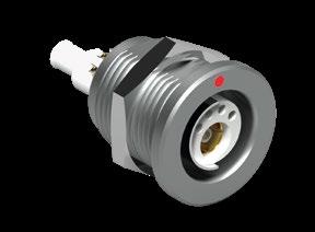
Torque [Nm] are recommended values that may be influenced by the quality of the panel surface. Tests must be conducted to evaluate the exact values.
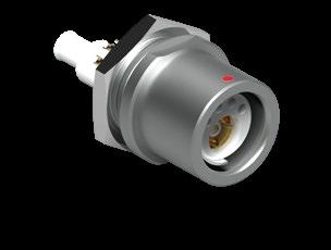
All dimensions and images shown are in millimeters and are for reference only.
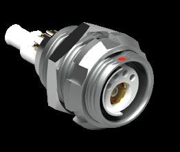
1) Assembly tool for decorative slotted nut, see Tooling section, page B 6-20 for details.
Body style SF
Unsealed (IP50)
Protection
Sealed up to IP68
Hermetic
Crimp (coax)
Contacts
Housing color
Assembly
Solder (others)
PCB
Natural chrome
Black chrome
Front-mounting
Rear-mounting
Sealing caps
Spacers
Color-coded washers
Accessories
Size
Insulating washers
Grounding washers
Locking washers
102 Size
All dimensions and images shown are in millimeters and are for reference only.
Links to detailed information
Sealing categories, page A-6
Electrical & contact configurations, page B 5-16
Options, section B 3-26
Body styles, page B 1-2
Accessories, page B 6-2
Technical dimensions, page B 5-12
For more information visit: www.fischerconnectors.com/technical
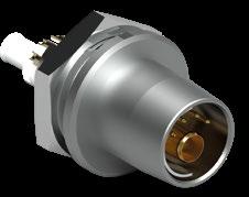
Torque [Nm] are recommended values that may be influenced by the quality of the panel surface. Tests must be conducted to evaluate the exact values.
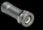
Body style
Protection
Contacts
Housing color
Design
Unsealed (IP50)
Sealed up to IP68
Crimp (coax)
Solder (others)
Natural chrome
References to detailed information
Sealing categories, page A-6
Electrical & contact configurations, page B 5-16
Options, page B 3-26 Black chrome
Flush
Front-projecting
Panel mounted
Front-mounting
Assembly
Rear-mounting
Cable mounted
Cable clamp sets
Cable bend reliefs
Sealing caps
Spacers
Accessories
Color-coded washers
Insulating washers
Grounding washers
Locking washers Size
Body styles, page B 1-3
Insulating cable clamp sets, page B 2-59
Accessories, page B 6-2
Technical dimensions, page B 5-14
For more information visit:
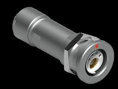
Torque [Nm] are recommended values that may be influenced by the characteristics of the cable jacket. Tests have to be made to evaluate the exact values. To secure the cable clamp nut, we recommend the use of thread locking adhesive.
1) Cable assembly operation possible only after housing mounted on panel
1) See list of recommended cables on page B 3-24.
2) Test voltages between contact and body, as well as between contact and coaxial outer contact.
3) Current per contact at 40°C temperature rise measured on the basic curve according to IEC 60512-5-2-5b. For the max. operating current a reduction factor must be used and limitations due to the size of the wires and the permissible upper temperature limit of the materials employed must be taken into account. See page A-12 for details.
4) PEEK for main insulator and PTFE for Coax.
5) Measured with S plug and D receptacle.
6) DB body style not available. = Standard = Option
All dimensions and images shown are in millimeters and are for reference only.
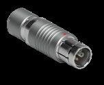
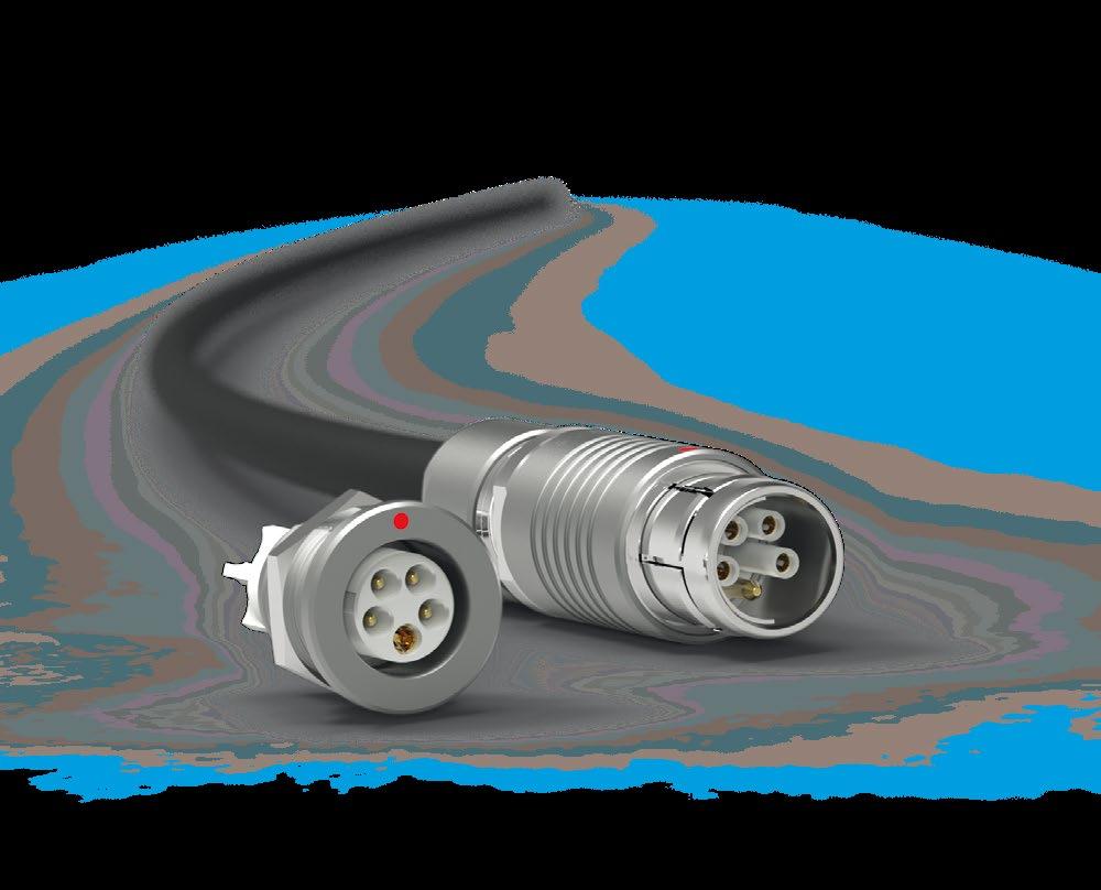
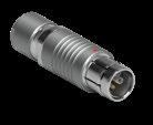
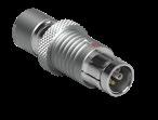
Body style S SV
Unsealed (IP50)
Protection
Sealed up to IP68
Locking system Friction
Push-pull
Quick-release Lanyard
Tamperproof
Contacts Crimp
Housing color
Design
Cabling
Links to detailed information
Sealing categories, page A-6
Locking systems, page A-5
Electrical & contact configurations, page B 5-21 Solder
Natural chrome
Options, page B 3-26 Black chrome
Shortened body
Right-angle
Cable clamp sets
Overmoldable
Heat shrinkable
Cable bend reliefs
Accessories
Body styles, page B 1-2
Insulating cable clamp sets, page B 2-59
Cable assembly, page A-16
Accessories, page B 6-2
Technical dimensions, page B 5-18
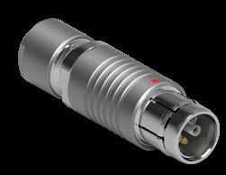
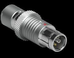
For insertion of female high voltage contacts which have to be assembled after wiring, we recommend tool TP00.000, shown on the Tooling section, page B 6-24.
These connectors are supplied with insulating cable clamps sets. The available inner diameters are listed on page B 2-59.
Some of these versions, however, can be delivered with special metal clamps, allowing the clamping of a cable screen. Please contacrt us for more information.
Torque [Nm] are recommended values that may be influenced by the characteristics of the cable jacket. Tests must be conducted to evaluate the exact values. To secure the cable clamp nut, we recommend the use of thread locking adhesive.
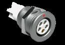
Body style
Protection
Contacts
Housing color
Unsealed (IP50)
Sealed up to IP68
Hermetic
Crimp
Solder
PCB
Natural chrome
Black chrome
Right-angle
Flush
Design
Assembly
Accessories
Front-projecting
Bulkhead feedthrough
Front-mounting
Rear-mounting
Sealing caps
Spacers
Color-coded washers
Grounding washers
Locking washers
Sealing categories, page A-6
Electrical & contact configurations, page B 5-21
Options, page B 3-26
Body styles, page B 1-3
Accessories, page B 6-2
Technical dimensions, page B 5-20
For more information visit: www.fischerconnectors.com/technical
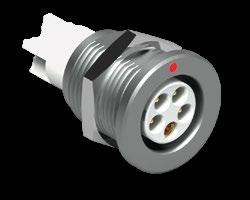
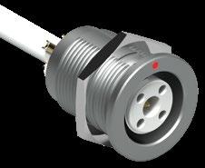
1)105 Size
The high voltage center contact is retained in a special insulator. To achieve proper high voltage performance, the window for soldering of the wire has to be covered by the supplied insulating tube, which must be placed over the cable before soldering.
2) The D 106 A014 is supplied with a slotted nut. The required hook spanner TX00.106 is shown on page B 6-20. For insertion of male high voltage contacts which have to be assembled after wiring, we recommend tool TP00.001, shown on page B 6-24.
Torque [Nm] are recommended values that may be influenced by the quality of the panel surface. Tests must be conducted to evaluate the exact values.
For Mixed High Voltage connectors, it is essential to pay attention to the differences between type "A" and "Z".
The contacts of the receptacle are recessed to reduce the possibility of electric shock in the unmated position.
This version should be used when the voltage is sourced from the receptacle.
The contacts of the plug are recessed to reduce the possibility of electric shock in the unmated position.
This version should be used when the voltage is sourced from the plug.
Protected contacts are usually female contacts recessed in the insulator. For Mixed High V oltage connectors, however, it is safer to recess the male contacts.
In these cases, the plug type "A" is equipped with female contacts and the receptacle with protected male contacts.
This applies to all connectors on page B 5-24 except 104 083 and 105 A 112.
1) Current per contact at 40°C temperature rise measured on the basic curve according to IEC 60512-5-2-5b. For the max. operating current a reduction factor must be used and limitations due to the size of the wires and the permissible upper temperature limit of the materials employed must be taken into account. See page A-12 for details.
2) Contact dia 2.0 is positioned to make contact first and break last.
3) See Tooling section, page B 6-23, for insertion tool of contact dia. 2.0.
4) HV contacts are female and LV contact is male on plug.
5) All contacts are male on plug with type A standard polarity.
6) Measured with S plug and D receptacle.
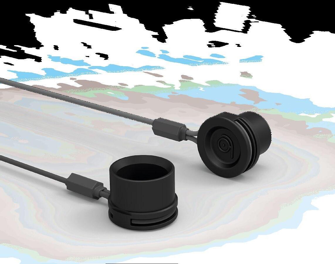
Suitable for :
Cable mounted plugs (S/SC, SOV, SA, SV, WSO)
Cable mounted receptacles (K/KE)
Panel mounted cable receptacles (DKBE, DK, DKE)
Prevent cable torsion and increase protection of connection.
Color coding for easy identification when combined with color washer on a panel mounted connector.
Suitable for :
Cable mounted plugs (S/SC, SOV, SA, SV, WSO)
Cable mounted receptacles (K/KE)
Panel mounted cable receptacles (DKBE, DK, DKE)
Facilitates grip for a heat shrinkable tube acting as cable bend relief.
PROTECTIVE SLEEVES
FOR IMPROVED PROTECTION
Suitable for :
Cable mounted plugs (S/SC, SOV)
Cable mounted receptacles (K/KE)
Protect against any foreign matter :
Dust, dirt or mud
Liquid splash
Minimize mechanical damage from impact on hard surfaces.
When mated, the front end of the protective sleeve encloses the projecting portion of the receptacle. When unmated, connectors can be protected with sealing caps.
FOR PROTECTION OF UNMATED CONNECTORS IN THE FIELD
Suitable for:
Cable mounted plugs (S/SC, SOV, SA, SV, SS/SSC, WSO)
Cable mounted receptacles (K/KE, KS/KSE)
Suitable for:
Panel mounted receptacles (D, DEU/E, DB, DBEU/E, DBP, DBPU/E, DBPLU/E, DG/DGP, DBPC, WDE)
Panel mounted plugs (SF, SFU/E, SFPU/E)
Panel mounted cable receptacles (DKBE, DK, DKE)
Lightweight
Noiseless operation
Operating temperature – 55°C to + 85°C
IP68
Easily installed
Available in single-piece or lanyard model
Intermateable to provide additional dust protection
Rugged
Fitted with an o-ring seal
Operating temperature – 30°C to + 200°C
Protect & seal the mating face of the connector
IP68
State colors available
Suitable for :
Feedthrough (WDE)
Panel mounted receptacles (DEE, DEU, DKE)
Enables mounting on panels or bulkheads thinner than the unthreaded section.
Suitable for :
Panel mounted receptacles (D, DB, DBP, DBPC, DG, DGP, DK)
Panel mounted plug (SF)
Can be mounted between the connector flange and the panel.
Color coding for easy identification when combined with colored cable bend relief for cable mounted connectors.
Not suitable for sealed version.
FOR EASY CONNECTOR IDENTIFICATION AND EFFICIENT INSULATION
TO ALLOW SECURE MOUNTING ON ALL PANELS
Suitable for panel mounted receptacle (D):
Can be mounted on both sides of the panel cut-out
Color coding for easy identification when combined with colored cable bend relief for cable mounted connectors.
Isolate the connector body electrically from the panel
Not suitable for sealed versions
Suitable for panel mounted connectors
Suitable for panel mounted connectors
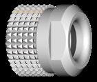
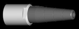
Material: nickel and chromium plated brass (ISO CuZn39Pb3)
1) For the 102 Size, cable bend reliefs are designed specifically for a given cable ø range. For all other Sizes, cable bend reliefs have to be cut to length L1, L2, L3 or L4 to fit your cable ø range.
Material:
Clamp nut : nickel and chromium plated brass (ISO CuZn39Pb3)
Bend relief : TPE (Thermoplastic elastomer)
These cable bend reliefs cannot be assembled with the clamp nuts supplied with the standard connectors. Therefore, the cable bend reliefs are supplied as sub-assemblies.
All dimensions and images shown are in millimeters and are for reference only.
BLACK CHROME CONNECTORS
1) For the 102 Size, cable bend reliefs are designed specifically for a given cable ø range. For other Sizes, cable bend reliefs have to be cut to
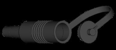
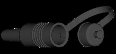
dimensions and images shown are in millimeters and are for reference only.
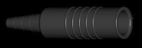
For S, SC and SOV For K and KE
TPE ( Thermoplastic elastomer).
Material: TPE ( Thermoplastic elastomer).
These protective sleeves for straight cable plugs and cable receptacles have grooved cable bend reliefs which can be shortened according to cable diameters. The lengths of the sleeves and the corresponding cable diameters are listed above.
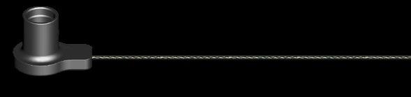


Material: cap: SantopreneTM TPV 101-80 Cord: Polyester.
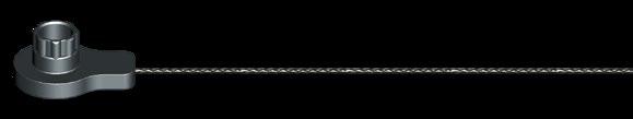
Crimp ferrule, crimp lug and heat shrink tube have to be ordered separately.
To attach the crimp ferrule or the crimp lug to the polyester cord, use a crimp tool, a vice or a pair of pliers with parallel jaws. There are no specific Fischer Connectors tools.
dimensions and images shown are in millimeters and are for reference only.
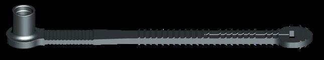
Material: cap: SantopreneTM TPV 101-80.
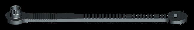
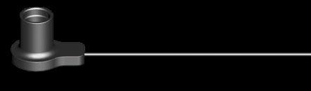


Crimp ferrule (300.922) and heat shrink tube (300.930) are included.
Material: cap: SantopreneTM TPV 101-80 Cable: Stainless steel with FEP-Teflon® covering.
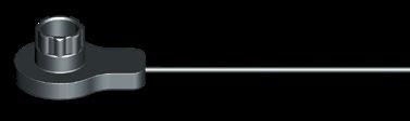


Crimp ferrule (300.922), crimp lug (300.299) and heat shrink tube (300.930) are included.
To attach the crimp ferrule or the crimp lug to the stainless steel cable, use a crimp tool, a vice or a pair of pliers with parallel jaws. See page B6-22 for recommended crimping tool for ferrule.
dimensions and images shown are in millimeters and are for reference only.
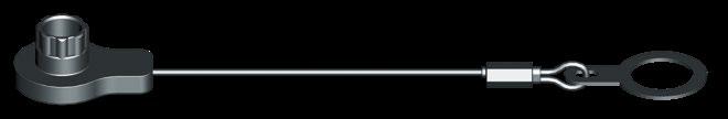
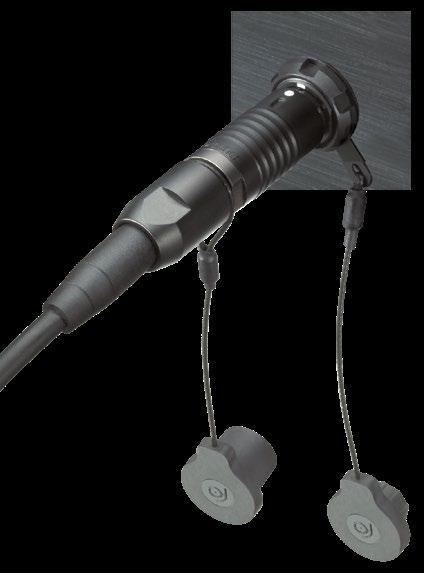
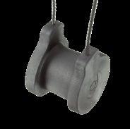
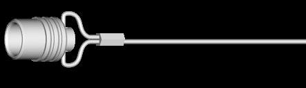
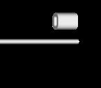
Material: cap: natural or black chrome plated brass (ISO CuZn39Pb3) – Crimp ferrule: aluminium.
These metal caps are fitted with an O-ring seal. They protect and seal the mating face of the plugs and receptacles.
To attach the crimp ferrule or the crimp lug to the stainless steel cable, use a crimp tool, a vice or a pair of pliers with parallel jaws. See page B6-22 for recommended crimping tool for ferrule.
1) Assembled with natural plastic covered stainless steel cable.
2) Assembled with black plastic covered stainless steel cable.
3) Not recommended for SFU; SFE; SFPE; SFPU. Use a soft cap instead.
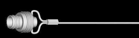
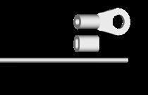
Material: cap: natural or black chrome plated brass (ISO CuZn39Pb3) – Crimp ferrule: aluminium – Crimp lug: tin plated copper.
All dimensions and images shown are in millimeters and are for reference only.
Material: aluminium.
Material: aluminium.
1) Spacers are useful and available for DKE only in 102 and 103 Sizes.
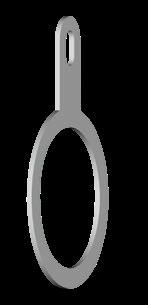
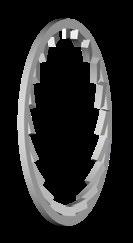

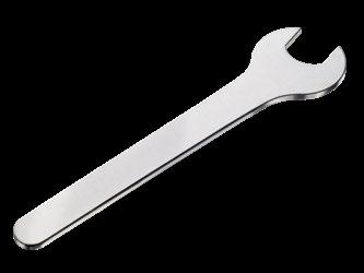

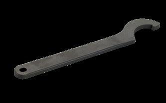

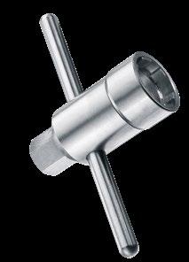
Material: hardened tool steel, gunmetal finish.
Material: hardened tool steel, nickel plated.
CRIMP TOOL ULTRA PRECISION
FOR CLOSED C CRIMP TERMINATION
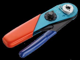
TX00.242 1.6 ASTRO TOOL 615708
The best choice of precision crimp tools for highly reliable eight indenter crimping per US-MIL, IEC and DIN specifications.
Positioners have to be ordered according to contact.
Standards
IEC 60203 / DIN 41 611, Part 3 / MIL- C-22520, Class I, Type 1
All dimensions and images shown are in millimeters and are for reference only.
FISCHER POSITIONER
SUITABLE FOR CRIMP TOOL TX00.240
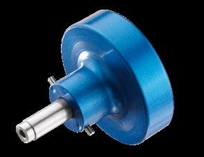
SUITABLE FOR CRIMP TOOL TX00.242
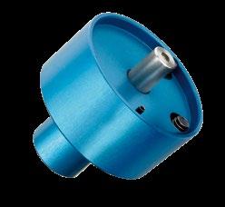
For the choice of Fischer Connectors’ positioner, please refer to page B2-26.
CRIMP TOOL FOR COAXIAL CABLE
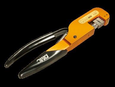
TX00.241
The crimp tool for coaxial cable features a system of interchangeable dies (see below) that accommodate coaxial connectors and contacts used by Fischer Connectors.
SUITABLE FOR CRIMP TOOL TX00.241
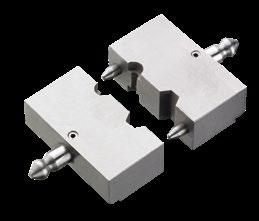
Part
TX00.250
TX00.251
Description
Special crimping dies for coaxial cables of cable group 1 (RG-174 etc.).
The hexagon corresponds to IEC 60803-B.
Special crimping dies for coaxial cables of cable group 4 (RG-58 etc.).
The hexagon corresponds to IEC 60803-D.
See page B3-23 for the table of cable designation. 2.7
TX00.265
Special crimping dies for crimp ferrule 300.922 of sealing caps
Part
TX00.214 0.5
TX00.210 0.7 TX00.211
Material:
Handle: black POM (Delrin®).
Fork: tool steel, chrome plated.
Tool for inserting male and female removable crimp contacts into the contact block. Especially recommended for small gauge and fragile wires.
TX00.213 0.5
TX00.200 0.7
TX00.205 0.9
TX00.212 1.3
TX00.201 1.6
Material:
Housing and plunger: black POM (Delrin®).
Sleeve: stainless steel.
Slide: tool steel.
Tool for extracting male and female removable crimp contacts from the contact block. The sleeve of this tool is pushed over the contact, to release the contact retaining mechanism. The tool plunger is then pushed to eject the contact.
dimensions and images shown are in millimeters and are for reference only.
FOR MALE CONTACTS WITH OUTSIDE THREAD
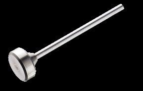
TP00.001
FOR FEMALE CONTACTS WITH INSIDE THREAD
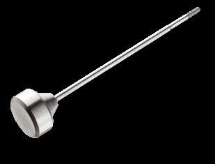
Tool for special contacts which are inserted only after termination to a wire 1)
To be used for :
- Multipole HV Cable receptacle 107 A034
- Coax HV Plugs 105 A005 & 105 A108
- Mixed HV Cable receptacles 105 A020,105 A036,105 A060 Receptacles 106 A014 Part
TP00.000
Tool for special contacts which are inserted only after termination to a wire 1)
To be used for :
- Multipole HV Plug 107 A034
- Coax HV Plugs 105 Z005 (right-angle only) & 105 Z049 Receptacles 105 A049, 105 A108
- Mixed HV Plugs 105 A020, 105 A036, 105 A060 & 106 A014
1) Warning: these contacts are not removable after insertion into the contact block.
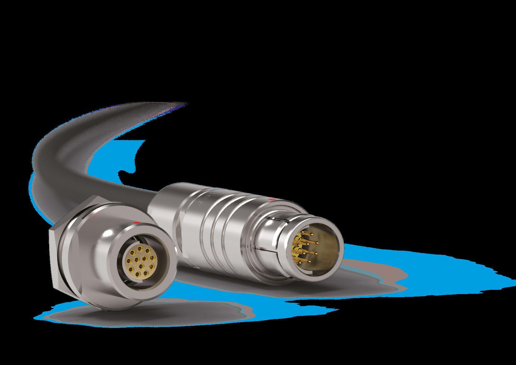
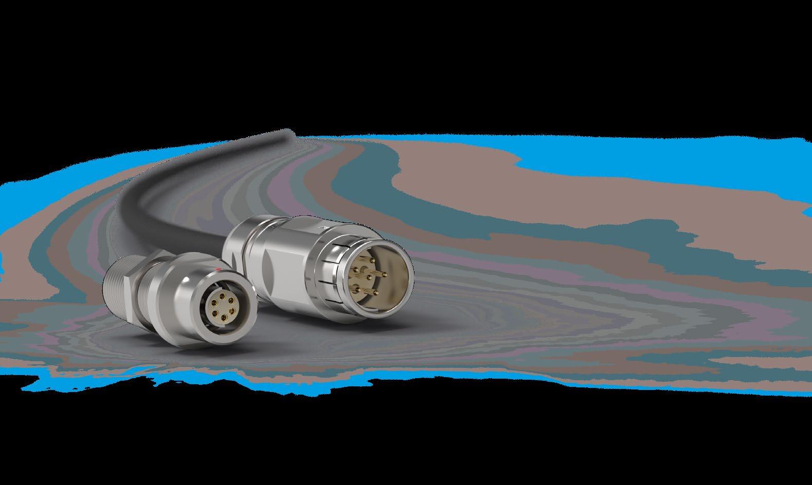


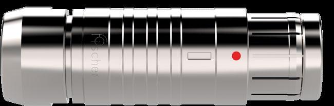
dimensions and images shown are in millimeters and are for reference only.
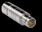
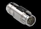
Body style
Protection
Unsealed (IP50)
Sealed up to IP68
Locking system Friction
Push-pull
Quick-release
Lanyard
Tamperproof
Contacts Crimp
Housing
Design
References to detailed information
Sealing categories, section A-6
Locking systems, page A-5
Electrical & configurations, page B 7-10 Solder
Standard
Remote handling
Shortened body
Straight Right-angle
Cable clamp sets
Cabling
Overmoldable
Heat shrinkable
Cable bend reliefs
Accessories
Protective sleeves
Sealing caps
103 Series
Size
Options, page B 7-17
Body styles, chapter B7-4
Cable clamp sets, page B 7-20
Accessories, pages B6-10 and B7-24
Technical dimensions, page B 7-5
For more information visit our website www.fischerconnectors.com/technical 105 Series
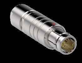
Torque [Nm] are recommended values that may be influenced by the characteristics of the cable jacket. Tests must be conducted to evaluate the exact values. To secure the cable clamp nut, we recommend the use of thread locking adhesive.
All dimensions and images shown are in millimeters and are for reference only.
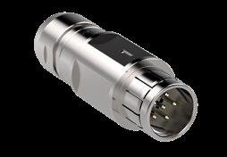

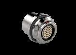
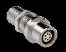
Body style
Protection
Contacts
Housing color
Unsealed (IP50)
Sealed up to IP68
Hermetic
Crimp
Solder
PCB
Natural chrome
Black chrome
Right-angle
Flush
Design
Front-projecting
Rear-projecting
Bulkhead feedthrough
Front-mounting
Assembly
Rear-mounting
Sealing caps
Spacers
Accessories
Color-coded washers
Grounding washers
Locking washers
103 Series
105 Series
107 Series
References to detailed information
Sealing categories, page A-6
Electrical & contact configurations, page B 7-10
Options, page B 7-17
Body styles, page B7-6
Accessories, pages B7-24, B6-16 and B6-18
Technical dimensions, page B 7-7
For more information visit our website www.fischerconnectors.com/technical
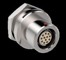
All dimensions and images shown are in millimeters and are for reference only.

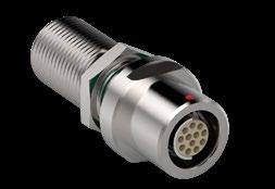
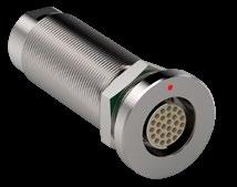
The bulkhead feedthrough connector allows the passing of electrical signals and power through a panel via two cable plugs.
The "AZ" version of the feedthrough accepts a type "A" plug on the flange side and a type "Z" plug on the threaded end, which is typically oriented toward the interior of the chassis. In the version "ZA" the connections "A" and "Z" are inverted.
Dimension "B max" specifies the maximum panel thickness. For panels thinner than the unthreaded section "E min", we can provide spacers as shown accessories section, page B 6-16.
1) Assembly tool for side hex nut, see Accessories section, page B 7-25.
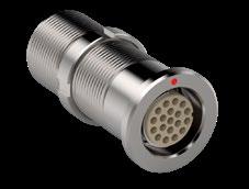
The bulkhead feedthrough connector allows the passing of electrical signals and power through a panel via two cable plugs.
The "AZ" version of the feedthrough accepts a type "A" plug on the flange side and a type "Z" plug on the threaded end, which is typically oriented toward the interior of the chassis. In the version "ZA" the connections "A" and "Z" are inverted.
Dimension "B max" specifies the maximum panel thickness. For panels thinner than the unthreaded section "E min", we can provide spacers as shown in accessories section, page B 6-16.
1) Assembly tool for side slotted nut, see Accessories section, page B 7-25.
Torque [Nm] are recommended values that may be influenced by the quality of the panel surface. Tests must be conducted to evaluate the exact values.
All dimensions and images shown are in millimeters and are for reference only.
To protect users from contact with dangerous voltages, most of our connectors exist in two versions:
STANDARD "A" POLARITY
The contacts of the receptacle are protected against accidental touch.
Recommended when voltage is present on the receptacle.
INVERTED "Z" POLARITY
The contacts of the plug are protected against accidental touch.
Recommended when voltage is present on the plug.
Standard Polarity
Type "Z"
Inverted Polarity
IMPORTANT : AN "A" TYPE CONNECTOR CAN NEVER BE MATED WITH A "Z" TYPE CONNECTOR.
A plug "ST-S" has the same housing in type "A" as in type "Z", but type "A" comes with unprotected contacts while type "Z" is equipped with
touch-protected contacts. In most cases these are female contacts which are recessed in the insulator.
BULKHEAD FEEDTHROUGH WDE
Type "AZ" is the standard version of the STWDE. The flange side accepts an "A" type plug, and the threaded side accepts a "Z" type plug.
The Fischer Connectors’ contact designs are highly reliable and are guaranteed up to 5,000 mating cycles.
All standard brass and bronze contacts for use in the Core Series are screw machined, and all are gold plated over a nickel underplate.
Most connectors are available with solder, crimp or PCB contacts and each type is optimized for a particular application.
Most versatile
Pre-installed contacts
Qualified assemblers required
Can be produced with any type of contact block material and accept a wide range of wire sizes.
Contacts are pre-installed in the insulator block, and the wires can be terminated with any appropriately sized soldering iron.
May require operators who are qualified in specialized soldering techniques.
PCB or Flex circuit mount
Reduced pin diameter
Wave soldering
Designed to be mounted directly onto a PCB or flex circuit, can be used in wave soldering operations for faster production assembly.
Preferred for high rates of data transmission due to the low distance to the board that their integration allows. This helps reducing signal perturbations.
PCB pins are generally used on rear mounted panel connectors.
dimensions and images shown are in millimeters and are for reference only.
Selectively annealed area
Special tools required
Limited range of wire sizes
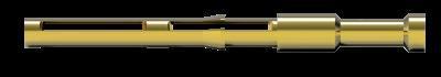
Each contact has a selectively annealed area which is deformed during assembly by specialized tooling to assure proper termination of the wire to the contact.
Commonly used for field termination or repair, as no soldering process is required.
Not available for sealed or hermetic connectors.
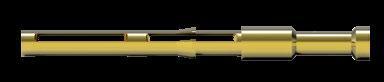
Selectively annealed area
Special tools required
Limited range of wire sizes
TOOLING FOR CRIMP CONTACTS
Each contact has a selectively annealed area which is crushed during assembly by specialized tooling to ensure proper termination of the wire to the contact.
Commonly used for field termination or repair, as no soldering is required.
Not available for sealed or hermetic connectors.
See following pages for description of crimp tool and positioner.
Please refer to www.fischerconnectors.com/technical for detailed information and assembly instructions.
103 A 058 Z 8 PEEK 0.7
103 A 062 Z 12 PEEK 0.5
1) Stranding values are in brackets.
[1]
max ø0.43mm
[1]
[19/40]
2) For a given AWG, the diameter of some stranded conductor designs could exceptionally be larger than the hole diameter of the barrel. Testing may be required.
3) Current per contact at 40°C temperature rise measured on the basic curve according to IEC 60512-5-2-5b. For the max. operating current a reduction factor must be used and limitations due to the size of the wires and the permissible upper temperature limit of the materials employed must be taken into account. See page A-12 for details.
4) Recommended operating voltage at sea level measured according to IEC 60664-1.
5) Measured with ST-S plug and ST-D receptacle. Please contact us for rating for ST-WSO right-angle plugs and ST-WDE bulkhead feedthroughs.
= Standard
1) Stranding values are in brackets.
2) For a given AWG, the diameter of some stranded conductor designs could exceptionally be larger than the hole diameter of the barrel. Testing may be required.
3) Current per contact at 40°C temperature rise measured on the basic curve according to IEC 60512-5-2-5b. For the max. operating current a reduction factor must be used and limitations due to the size of the wires and the permissible upper temperature limit of the materials employed must be taken into account. See page A-12 for details.
4) Recommended operating voltage at sea level measured according to IEC 60664-1.
5) Contact dia. 2.0 is positioned to make contact first and break last.
6) Measured with S plug and D receptacle.
1) Stranding values are in brackets.
2) For a given AWG, the diameter of some stranded conductor designs could exceptionally be larger than the hole diameter of the barrel. Testing may be required.
3) Current per contact at 40°C temperature rise measured on the basic curve according to IEC 60512-5-2-5b. For the max. operating current a reduction factor must be used and limitations due to the size of the wires and the permissible upper temperature limit of the materials employed must be taken into account. See page A-12 for details.
4) Recommended operating voltage at sea level measured according to IEC 60664-1.
5) Contacts dia. 1.3 are positioned to make contact first and break last.
6) Contacts dia. 1.6 are positioned to make contact first and break last.
7) Inverted polarity: female contacts on plug/male contact on receptacle
8) Measured with S plug and D receptacle.
max ø0.79mm AWG21 [1] AWG22 [7/30]
max ø0.88mm AWG20 [1] AWG22 [19/34]
1) Stranding values are in brackets.
2) For a given AWG, the diameter of some stranded conductor designs could exceptionally be larger than the hole diameter of the barrel. Testing may be required.
3) Current per contact at 40°C temperature rise measured on the basic curve according to IEC 60512-5-2-5b. For the max. operating current a reduction factor must be used and limitations due to the size of the wires and the permissible upper temperature limit of the materials employed must be taken into account. See page A-12 for details.
4) Recommended operating voltage at sea level measured according to IEC 60664-1.
5) Measured with S plug and D receptacle.
For easy connect/disconnect operations
Our contact blocks are engineered with arc-shape metal guides, which ensure precise alignment of connectors during the mating process.
This guiding mechanism provides:
Increased safety and user friendliness by preventing misconnection.
Easy mating cycles, can be blind-mated.
Keying codes option
All Multipole body styles are mechanically coded. Code 1 is the standard, but other codes can be requested.
Code 1
Receptacle
Other keying codes are available on request, please contact us. Images are for reference only.
OPTIONS
1 Housing color Which housing color do you need ? Natural Stainless steel
2 Contact block material Which contact block material do you need ? PEEK
3 Contact type Which contact type do you need ? Solder Crimp1)
4 Keying code Which keying code do you need ? Code 1 -130 -150
1) Crimp contacts are not an option for sealed or hermetic connectors.
Applicable for Last digit Description
0 Standard : solder contacts
Front mounted : ST-DBEE
All dimensions and images shown are in millimeters and are for reference only.
Rear mounted : ST-DBPE
9 With PCB (Printed Circuit Board) contacts instead of solder contacts
0 Standard : PCB (Printed Circuit Board) contacts
9 With solder contacts instead of PCB (Printed Circuit Board) contacts
Options are available on request, please contact us.
How to build a part number
Refer to the table aside to find the information you need to build the part number to order your selected connector.
For customized solutions, please contact us.
ST- S cable mounted plug in Series 103 with 6 (multipole) low voltage male contacts and following options.
ST- DBEE panel mounted receptacle in Series 103 with 6 (multipole) low voltage female contacts and following options.
Cable mounted plugs Series As standard rule
A = male contacts on plug and female contacts on receptacle
Panel mounted receptacles
ST-DBEE
ST-DBPE
ST-WDE
See page B 7-3 or Technical dimensions B 7-5
Z = female contacts on plug and male contacts on receptacle
See page B 7-10
056 -130
Stainless steel housing, PEEK contact blocks with solder contacts, keying code 1 and clamp nut without bend relief.
056 -130E Not applicable as panel mounted
Stainless steel housing, PEEK contact blocks with solder contacts and keying code 1.
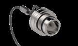
Stainless steel cap Crimping tool
Three-digit number specific for each pin layout
Specific suffix corresponding to selected options
Below cable clamp sets should be ordered separately
Housing color Multipole low voltage
Protective sleeves
Soft caps
Metal caps
Spacers
Washers
Mounting nuts Spanners / Wrenches Crimping tools
Tools for crimp contacts and high voltage contacts
Contact type
Solder Crimp PCB
Keying code of the contact block
Clamp nut type & color
Other options
See page B 7-17
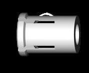
To guarantee excellent cable retention and strain relief, Fischer Connectors provides robust and high quality cable clamp sets : Collet style clamp system retaining cable over large jacket surface area. Protection of small diameters and delicate conductors.
Cable clamp sets are suitable for all cable mounted connectors.
Fischer Connectors offers three types of cable clamps sets. The table below will help you select the one corresponding to your needs.
Cable clamp sets below should be ordered separately
Multipole low voltage
Cable clamp set
S - Shielded
U - Unshielded
E - Environmental
Do you need the interface between the cable and the connector to be sealed ?
Do you need the connector to be terminated to the cable shield ?
Unsealed Sealed Unshielded Shielded
For 107 Series connectors, only S and E cable clamp sets are available.
ST- S 103 A056-130+
Examples connector ordering line
ST- S103 A056-130+
Clamp set ordering line
E3 102.5/2.0
See following pages for cable clamp sets selection.
Shielded cable clamp with spacer and sleeve.
UNSHIELDED
Unshielded, one-piece cable clamp.
Environmentally sealed clamp for use with shielded or unshielded cables.
dimensions and images shown are in millimeters and are for reference only.
Shielded cable clamp with spacer and sleeve.
Sleeve
Spacer
UNSHIELDED
Unshielded, one-piece cable clamp.
Environmentally sealed clamp for use with shielded or unshielded cables.
dimensions and images shown are in millimeters and are for reference only.
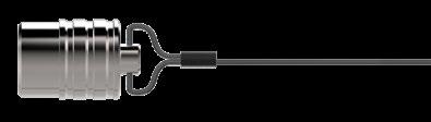

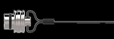
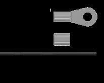
They protect and seal the mating face of the plugs and receptacles.
To attach the crimp ferrule or the crimp lug to the stainless steel cable, use a crimp tool, a vice or a pair of pliers with parallel jaws. See page B6-22 for recommended. Other available accessories listed on page B7-30. Cable strain relief, Protective Boots, sealing caps )Plastic, Soft caps).

OPEN-END SPANNER EXTRA THIN
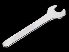

CRIMP TOOL ULTRA PRECISION
FOR CLOSED CRIMP TERMINATION
TX00.240
BALMAR 18 - 000 or DANIELS MH - 800
TX00.242 1.6 ASTRO TOOL 615708
The best choice of precision crimp tools for highly reliable eight indenter crimping per US-MIL, IEC and DIN Specifications. Positioners have to be ordered according to contact. Standards
IEC 60203 / DIN 41 611, Part 3 / MIL- C-22520, Class I, Type 1
POSITIONER
SUITABLE FOR CRIMP TOOL TX00.240

SUITABLE FOR CRIMP TOOL TX00.242
For the choice of Fischer Connectors’ positioner, please refer to section "Tooling", page B 2-26.

Part
TX00.214
TX00.210
Material
Handle: black POM (Delrin®)
Fork: tool steel, chrome plated
Tool for inserting male and female removable crimp contacts into the contact block. Especially recommended for small gauge and fragile wires.
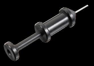
TX00.213
TX00.200
Material
Housing and plunger: black POM (Delrin®)
Sleeve: stainless steel
Slide: tool steel
Tool for extracting male and female removable crimp contacts from the contact block. The sleeve of this tool is pushed over the contact, to release the contact retaining mechanism. The tool plunger is then pushed to eject the contact.
dimensions and images shown are in millimeters and are for reference only.
Metal parts
Shell (Housing), clamp nut, decorative slotted nut
Cable clamp, inner sleeve, spacers and rings, nuts and washers Brass CuZn39Pb3 CW614N / UNS C 38500 Nickel SAE-AMS-QQ-N-290 / SAE-AMS2404
Contacts Male (solder) Brass CuZn39Pb3 CW614N / UNS C 38500 1 µm Gold over Nickel MIL-DTL-45204D / Type 1 + ASTM B488 Female, Male (crimp) Bronze CuSn4Zn4Pb4 CW456K / ASTM B 139 / UNS C 54400
Other material and surface treatments are available on request.
Contact blocks and other insulators for our standard connectors are manufactured from high performance engineering plastic materials. The standard materials for each connector series are listed under Electrical & contact configurations in pages B 7-13 through B 7-16. Ceramics and other dielectrics are available on special order.
Insulator and sealing International symbol Flammability
Insulator PEEK UL 94 V-O
Panel and contact block O-rings (receptacles) FPM (Viton ®) -
Interface O-rings (receptacles) EPDM -
Sealant material - IP68 (receptacles) - Hermetic Silicon compound Epoxy compound
Cable sealing (plugs) - IP68 TPE-S UL 94 HB
Our products are RoHs compliant and conform with the EC Directives 2002/95/EC.
Characteristic Product
Unsealed connectors (mated) IP50 IEC 60529
Plugs (mated) with general purpose sealed clamps 1) IP68 IP69
Sealing performance
Receptacles "U" body style IP68
Receptacles "E" body style
Hermetic: Tested: <10-8 mbar l/s IEC 60068-2-17 test Qk method 3, alternative b IP69 IEC 60529
Operating temperature range See details on page A-9 and page B7-30 IEC 60512-6-11 i+j / IEC 60068-2-14-Nb
Corrosion resistance Salt mist, 1000 hours, 5% salt solution, 35°C
Endurance 5000 mating cycles
Vibration
10 to 2000 Hz, 1.5 mm or 15g, 12 sweep cycles per axis, 20 minutes per 10-2000-10 Hz sweep cycle, no discontinuity > 1us
Radiation resistance 2) Unsealed connectors PEEK: 107 Gy (= 1000M Rads)
Sealed receptacles "E" FPM (Viton®) O-rings 105 Gy (= 10M Rads)
1) The sealing performance can be affected by the long term quality of the cable.
2) For information only. Not tested by Fischer Connectors.
Most of our connectors are completely sterilizable in autoclave, Cidex® , EtO, gamma radiation, Steris® or Sterrad®. Please contact us for more details. For more information visit: www.fischerconnectors.com
Characteristic
Contact resistance 5,000 mating cycles
IEC 60512-2-1, Test 2a IEC 60512-2-2, Test 2b
Insulation resistance > 1010Ω IEC 60512-3-1-3a Method C
All dimensions and images shown are in millimeters and are for reference only.
IEC 60068-2-11 test Ka
MIL-STD-202 method 101 condition A
IEC 60512-9-1 / EIA-364-09
MIL-STD-202 method 204 condition B
The temperature ranges quoted by the manufacturers of the plastic materials are usually the absolute maximum values. When exposed to the mechanical and electrical stresses present in a connector, these values are often unachieveable.
If a composite connector system including accessories is used, then the item
with the lowest temperature performance will dictate the operating temperature limit of the system. The table below shows our recommended operating temperature ranges.
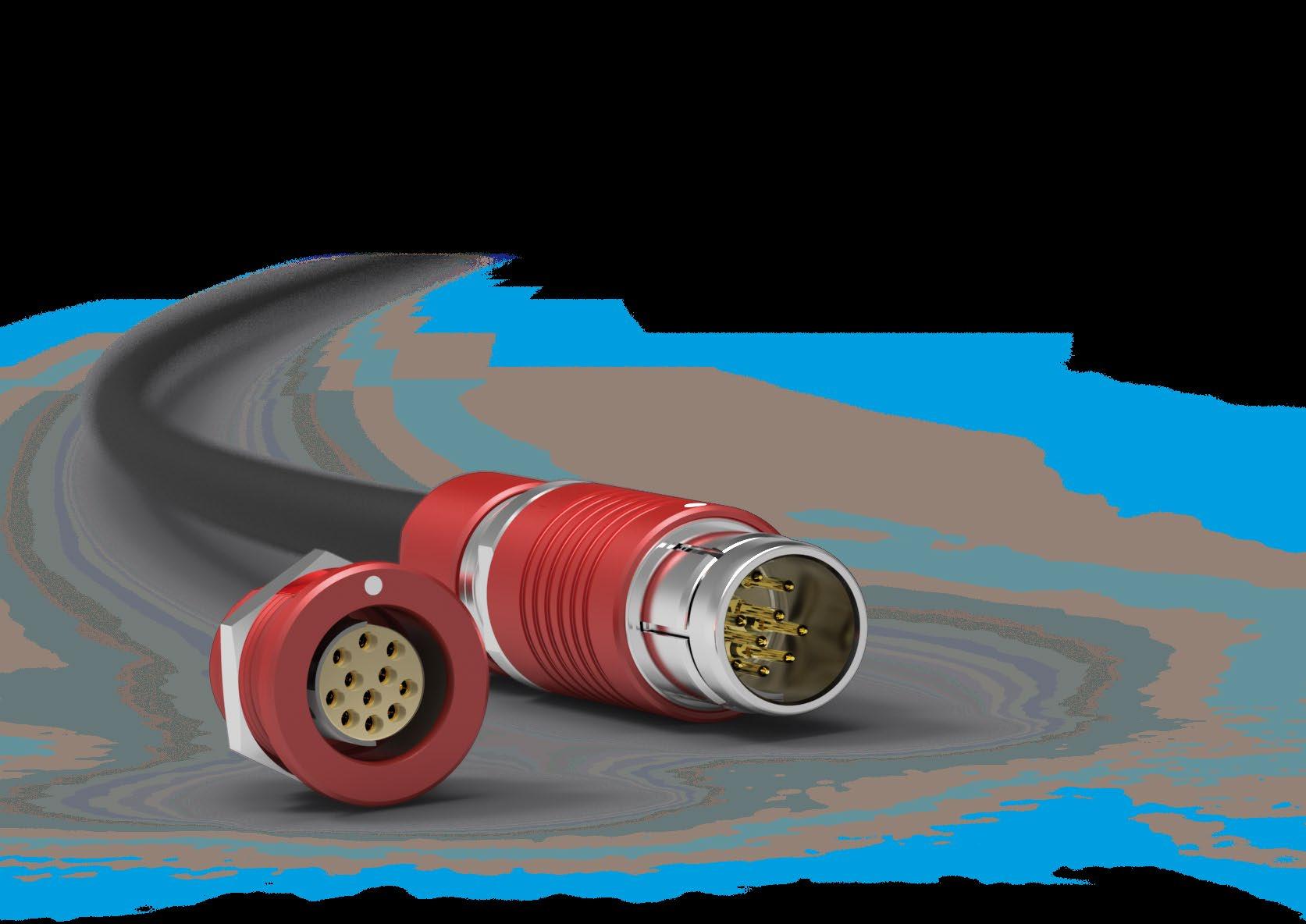
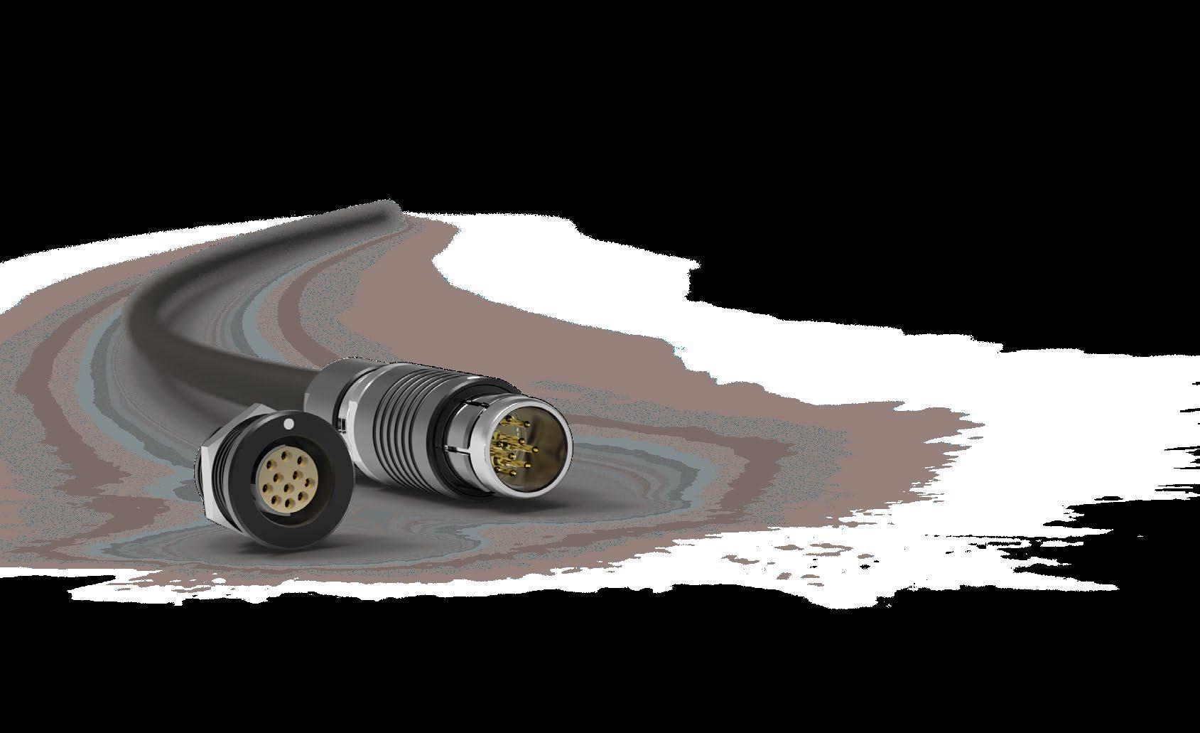

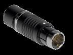

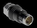
BODY STYLES S SC SS SSC
Locking system Push-pull Quick-release Push-pull Quick-release
Sealing IP50/ IP68 IP50/ IP68 IP50/ IP68
IP50/ IP68
Design Standard Standard Short/Overmolding Short/Overmolding
PANEL FRONT MOUNTED
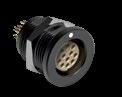
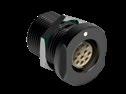
BODY STYLES D DEU DEE
Sealing IP50 IP68 Hermetic
Design Rear-projecting Rear-projecting
PANEL REAR MOUNTED
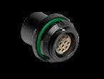
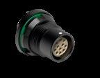
BODY STYLES DBPU DBPE DBPLU DBPLE
Sealing IP68 Hermetic IP68 Hermetic
Design Rear-projecting Front-projecting
*See full color selection in part numbering sections (pages B 8-6 B 8-9, B 8-11).
All dimensions and images shown are in millimeters and are for reference only.
Body style
Protection
Locking system
Contacts
Design
Cabling
Unsealed (IP50)
Sealed up to IP68
Push-pull
Quick-release
Crimp
Solder
Colored housing
Shortened body
Cable clamp sets
Overmoldable
Heat shrinkable
Other body styles available on request.
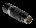
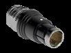
References to detailed information
Sealing categories, page A-6
Locking systems, page A-5
Electrical & contact configurations, page B8-12
Body styles, page B8-3
Cable clamp sets, page B 2-39
BODY STYLES
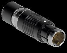
1) Weight shown is without cable clamp set, overmolding or heat shrinking.
2) Max. cable diameter below shield.
All dimensions and images shown are in millimeters and are for reference only.
STYLES
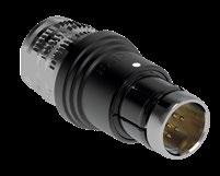
The configurator is designed for multipole contact blocks only. For coax or triax blocks, please contact us.
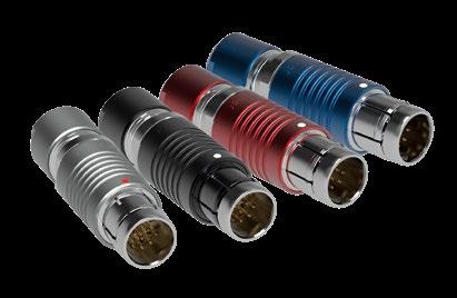
AL = Aluminum
Housing treatment Housing material
1231 = Black (chromium)
1411 = Blue (anodized)
1611 = Red (anodized)
1731 = Grey (chromium)
S = Standard body length
SS = Shortened body length
If standard automatic push-pull locking system is desired, leave field blank.
Other option possible : C = Clic Loc, quick-release
102, 103, 1031, 104, or 105 = Series
(See dimensions page B8-5)
For standard body length plugs (S) :
11 =Standard clamp nut, no bend relief.
(See pages B 8-19 to B 8-24)
For shortened body length plugs (SS) :
13 = For heat shrinking / boots
14 = For injection / overmolding
Keying code
11 = Code 1
12 = Code 2
13 = Code 3
= Solder CP = Crimp Three-digit
(see pages B 8-12 to B8 -18)
A = Male contacts on plug
Z = Female contacts on plug
1) Fischer Connectors cannot be held liable for small color variations that may appear from one batch to another.
Example 1
AL1231-S-103-A062SR11-11 Example 2
AL1231-S-103-A053SR11-11 AL1731-SS-102-A056SR12-13
Body Style
Protection
Unsealed (IP50)
Sealed up to IP68
Hermetic
Crimp
Contacts
Solder
PCB
Colored housing
Design
Assembly
Flush
Front-projecting
Front-mounting
Rear-mounting
Other body styles available on request.
All dimensions and images shown are in millimeters and are for reference only.
References to detailed information
Sealing categories, page A-6
Electrical & contact configurations, page B8-12
Body styles, chapter B8-3
BODY STYLES
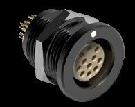
DEU/DEE
STYLES
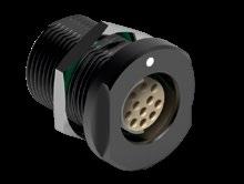
The configurator is designed for multipole contact blocks only.
For coax or triax blocks, please contact us.
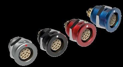
AL = Aluminum
1231 = Black (chromium) 1411 = Blue (anodized) 1611 = Red (anodized) 1731 = Grey (chromium)
D = Flush (vs. panel) Front-mounting receptacle
If no sealing level is desired, leave field blank. Other options possible :
EU = Sealed (IP68) even unmated
EE = Hermetic 102, 103, 1031, 104, or 105 = Series (See dimensions section)
1) Fischer Connectors can not be held liable for small color variations that may appear from one batch to another.
= Yes
= Hexagonal
12 = None
= No
If ‘No sealing level‘ chosen in section BC, leave field blank.
Options possible if you selected ‘Sealed (IP68) even unmated‘ or ‘Hermetic‘ :
11 = Viton
12 = EPDM (low temperature)
11 = Code 1
12 = Code 2
13 = Code 3
Options possible if no sealing level is required:
SR = Solder
CP =Crimp "D" only
PB = PCB
Options possible if selected sealing level is ‘Sealed (IP68) even unmated’ or ‘Hermetic’ :
SR = Solder
PB = PCB
Three-digit number (see pages B 8-12 to B8 -18)
A = Female contacts on receptacle
Z = Male contacts on receptacle
DBPU/DBPE BODY STYLES
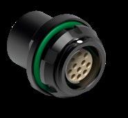
1) Weight includes nut.
2) Pin length and diameter vary according to contact configuration. Contact us for more information.
3) For information on nutdrivers ( ), see Tooling page B 8-29.
PANEL CUT OUT
BODY STYLES
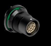
* – Pin for PCB contacts versions; all Series.
– Tag for solder contact versions; Series 103 to 107. – Barrel for solder contact versions; Series 102.
PANEL CUT OUT
The configurator is designed for multipole contact blocks only. For coax or triax blocks, please contact us.
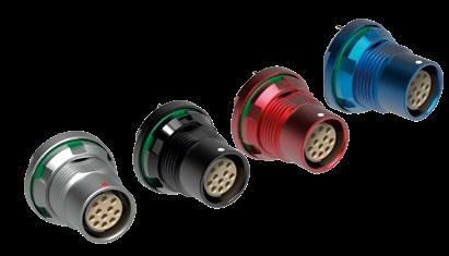
= Aluminum
Housing treatment
1231 = Black (chromium) 1411 = Blue (anodized) 1611 = Red (anodized) 1731 = Grey (chromium)
DBP = Flush (vs. panel) Rear-mounting receptacle
DBPL = Front-projecting (vs. panel) Rear-mounting receptacle
U= Sealed (IP68) even unmated
Example 1:
AL1231-DBPLU-102-A059PB12-12G13
Example 2:
AL1231-DBPLE-102-Z054SR11-11G13
E = Hermetic 102, 103, 1031, 104 or 105 = Series (See dimensions section)
1) Fischer Connectors can not be held liable for small color variations that may appear from one batch to another.
dimensions and images shown are in millimeters and are for reference only.
1) Wire gauge stranding values are in brackets.
2) For a given AWG, the diameter of some stranded conductor designs could exceptionally be larger than the hole diameter of the barrel. Testing may be required.
3) Current per contact at 40°C temperature rise measured on the basic curve according to IEC 60512-5-2-5b. For the max. operating current a reduction factor must be used and limitations due to the size of the wires and the permissible upper temperature limit of the materials employed must be taken into account. See page A-12 for details.
4) Recommended operating voltage at sea level measured according to IEC 60664-1.
5) Measured with S plug and D receptacle.
6) Plug with crimp contacts must be used with unshielded clamps only.
7) Only available for A polarity plugs.
1031A 012 Z 12
1031A 019 Z 19
1) Wire gauge stranding values are in brackets.
[1]
[19/40]
2) For a given AWG, the diameter of some stranded conductor designs could be larger than the hole diameter of the barrel. Testing maybe required.
3) Current per contact at 40°C temperature rise measured on the basic curve according to IEC 60512-5-2-5b. For the max. operating current a reduction factor must be used and limitations due to the size of the wires and the permissible upper temperature limit of the materials employed must be taken into account. See page A-12 for details.
4) Recommended operating voltage at sea level measured according to IEC 60664-1.
5) Measured with S plug and D receptacle.
1) Stranding values are in brackets.
2) For a given AWG, the diameter of some stranded conductor designs could be larger than the hole diameter of the barrel. Testing may be required.
3) Current per contact at 40°C temperature rise measured on the basic curve according to IEC 60512-5-2-5b. For the max. operating current a reduction factor must be used and limitations due to the size of the wires and the permissible upper temperature limit of the materials employed must be taken into account. See page A-12 for details.
4) Recommended operating voltage at sea level measured according to IEC 60664-1.
5) Test voltages between the contacts with the shortest distance.
6) Measured with S plug and D receptacle.
[1]
[7/30]
A124 5)
1) Stranding values are in brackets.
2) For a given AWG, the diameter of some stranded conductor designs could exceptionally be larger than the hole diameter of the barrel. Testing may be required.
3) Current per contact at 40°C temperature rise measured on the basic curve according to IEC 60512-5-2-5b. For the max. operating current a reduction factor must be used and limitations due to the size of the wires and the permissible upper temperature limit of the materials employed must be taken into account. See page A-12 for details.
4) Recommended operating voltage at sea level measured according to IEC 60664-1.
5) Solder and PCB contact types available only for DBPU and DBPLU receptacles. Crimp contact type available only for plugs.
6) Measured with S plug and D receptacle.
= Standard = Option
1) Stranding values are in brackets.
2) For a given AWG, the diameter of some stranded conductor designs could exceptionally be larger than the hole diameter of the barrel. Testing may be required.
3) Current per contact at 40°C temperature rise measured on the basic curve according to IEC 60512-5-2-5b. For the max. operating current a reduction factor must be used and limitations due to the size of the wires and the permissible upper temperature limit of the materials employed must be taken into account. See page A-12 for details.
4) Recommended operating voltage at sea level measured according to IEC 60664-1.
5) Contact dia. 2.0 is positioned to make contact first and break last.
6) Measured with S plug and D receptacle.
1) Stranding values are in brackets.
2) For a given AWG, the diameter of some stranded conductor designs could exceptionally be larger than the hole diameter of the barrel. Testing may be required.
3) Current per contact at 40°C temperature rise measured on the basic curve according to IEC 60512-5-2-5b. For the max. operating current a reduction factor must be used and limitations due to the size of the wires and the permissible upper temperature limit of the materials employed must be taken into account. See page A-12 for details.
4) Recommended operating voltage at sea level measured according to IEC 60664-1.
5) Contacts dia. 1.3 are positioned to make contact first and break last.
6) Contacts dia. 1.6 are positioned to make contact first and break last.
7) Inverted polarity: female contacts on plug/male contact on receptacle
8) Measured with S plug and D receptacle.
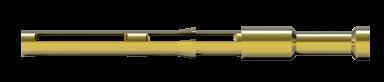
Selectively annealed area
Special tools required
Limited range of wire sizes
TOOLING FOR CRIMP CONTACTS
Each contact has a selectively annealed area which is crushed during assembly by specialized tooling to ensure proper termination of the wire to the contact.
Commonly used for field termination or repair, as no soldering is required.
Not available for sealed or hermetic connectors.
See section Tooling, section B 6-21, for description of Crimping Tool and Positioner.
Please refer to www.fischerconnectors.com/technical for detailed information and assembly instructions.
To guarantee excellent cable retention and strain relief, Fischer Connectors provides robust and high quality cable clamp sets :
Collet style clamp system retains cable over large jacket surface area.
Protection of small diameters and delicate conductors.
Can be combined with cable bend reliefs for optimal performance.
Cable clamp sets are used with cable mounted connectors, except SS/SSC which require overmolding or heat shrinking techniques.
RANGE OVERVIEW : S, U & E CABLE CLAMP SETS
Fischer Connectors offers three types of cable clamps sets.
The table below will help you select the one corresponding to your needs.
Do you need the interface between the cable and the connector to be sealed ?
Cable clamp set
S - Shielded
U - Unshielded
E - Environmental
PART NUMBERING
Cable clamp sets are ordered separately
Multipole low voltage
AL1731-S-102-A056SR11-11
Examples connector ordering line
AL1731-S-102-A056SR11-11
Clamp set ordering line
E3 102.5/2.0
See following pages for cable clamp set selection.
Do you need the connector to be terminated to the cable shield ?
Shielded cable clamp with sleeve and clamp.
UNSHIELDED
Unshielded, one-piece cable clamp.
Environmentally sealed clamp for use with shielded or unshielded cables.
SHIELDED Shielded cable clamp with sleeve and clamp.
UNSHIELDED
Unshielded, one-piece cable clamp. E
Environmentally sealed clamp for use with shielded or unshielded cables.
dimensions and images shown are in millimeters and are for reference only.
Shielded cable clamp with sleeve and clamp.
UNSHIELDED
Unshielded, one-piece cable clamp.
Environmentally sealed clamp for use with shielded or unshielded cables.
Shielded cable clamp with sleeve and clamp. U UNSHIELDED
Unshielded, one-piece cable clamp.
Environmentally sealed clamp for use with shielded or unshielded cables.
Shielded cable clamp with sleeve and clamp.
UNSHIELDED
Unshielded, one-piece cable clamp.
Environmentally sealed clamp for use with shielded or unshielded cables.
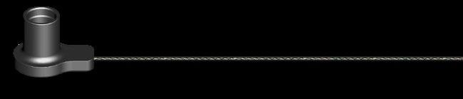
Crimp ferrule, crimp lug and heat shrink tube have to be ordered separately. Material: Cap: SantopreneTM TPV 101-80 Cord: Polyester.
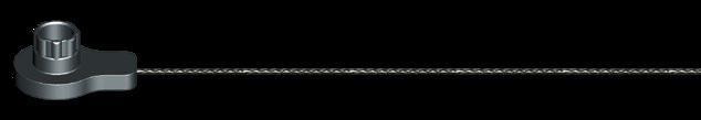
To attach the crimp ferrule or the crimp lug to the polyester cord, use a crimp tool, a vice or a pair of pliers with parallel jaws. There are no specific Fischer Connectors tools.
All dimensions and images shown are in millimeters and are for reference only.
Crimp ferrule (300.922) and heat shrink tube (300.930) are included. Material: Cap: SantopreneTM TPV 101-80 Cable: Stainless steel with FEP-Teflon® covering
To attach the crimp ferrule or the crimp lug to the stainless steel cable, use a crimp tool, a vice or a pair of pliers with parallel jaws. See page B6-22 for recommended crimping tool for ferrule.
dimensions and images shown are in millimeters and are for reference only.
Materials
Cap: SantopreneTM TPV 101-80
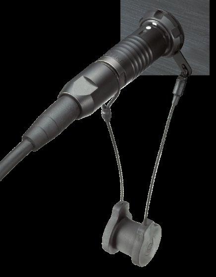
FOR
Thread
M9x0.5 15 TC00.000
M10x0.5 16 TC00.007
M14x1 21 TG00.001
M15x1 22 TK00.000
M16x1 23 TK00.002
M20x1 28 TP00.005
dimensions and images shown are in millimeters and are for reference only.
Parameter
Mating cycles
Operating temperature range
- Viton O-ring at plug interface
- EPDM O-ring (Low temp) at plug interface
Sealing
Hermeticity
- DEE, DBPE, DBPLE
Vibration
10,000
-20°C to +200°C
-50°C to +160°C
See details on page A-9 and B8-32
IP68 ; 2m submersion for 24 hours
Hermetic: Tested: <10-8 mbar l/s
IP69
Contact interruption < 1µs (10-2000Hz/15G)
Parameter
Grounding resistance1) (shell-to-shell) Typical 50 mΩ
EMC shielding 360-degree EMC shielding
1) IEC 60512-2-6-2f
* Please refer to contact block sections for detailed information.
Standard
IEC 60512-9-1
EIA-364-09
IEC 60068-2-14
IEC 60529
IEC 60068-2-17 test Qk method 3, alternative b IEC 60529
MIL-STD-202 Method 204, Condition B
Plug housing
- Body
- Latching sleeve
Receptacle housing
- Receptacle housing (anodized)
Grounding
- Tag (solder and crimp contacts)
- Pin (PCB contacts)
Contacts
- Male contacts
- Female contacts
Brass
or Brass
Bronze
Aluminum is not recommended for marine or corrosive environments. In this case, we recommend the Fischer Core Series Brass or Core Series Stainless Steel.
Contact blocks and other insulators for our standard connectors are manufactured from high performance engineering plastic materials. The standard materials of each connector series are listed under Electrical & Contact configurations in pages B 8-12 through B 8-18. Ceramics and other dielectrics are available on special order.
Insulator and sealing International symbol Flammability
Insulator PEEK - PTFE - PBT
94 V-O
Interface O-rings (receptacles) FPM (Viton ®) / EPDM -
Sealant material - IP68 (receptacles) - Hermetic Silicon compound Epoxy compound
Our products are RoHs compliant and conform with the EC Directives 2002/95/EC.
94 V-O
94 HB
The temperature ranges quoted by the manufacturers of the plastic materials are usually the absolute maximum values. When exposed to the mechanical and electrical stresses present in a connector, these values are often unrealistic. If a composite connector system including accessories is used, then the item with the lowest temperature performance will dictate the operating temperature limit of the system. The table below shows our recommended operating temperature ranges.
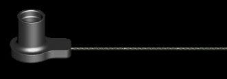
1
2
7
8
EASY TO USE | DURABLE | LIGHTWEIGHT
Sealed up to IP68
Over 5,000 mating cycles
Resistant to large temperarure variations Color coding for easy operation
PLUGS CABLE MOUNTED
BODY STYLES S 405 SI 405
Locking system Push-pull Push-pull
Sealing IP50/ IP67 IP50/ IP67
Design Standard Standard
Integral shielding Yes No
BODY STYLE DBP 405
Sealing IP50
Design Standard
COMPATIBILITY
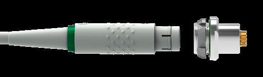
dimensions and images shown are in millimeters and are for reference only.
Mateable with all high performance Fischer Connectors’ panel receptacles of the Fischer Core Series Brass 105.
CABLE MOUNTED
S/SI 405 BODY STYLES
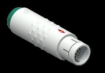
PANEL MOUNTED
DBP 405 BODY STYLE
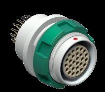
* See contact configurations page B 9-6.
PANEL CUT-OUT
Figure 1
All dimensions and images shown are in millimeters and are for reference only.
Example:
Body style
S = Plug, with integral shielding
SI = Plug, without integral shielding
DBP = Receptacle, rear panel mounted
Series
405
Contact polarity
A = Plugs have male contacts. Receptacles have female contacts.
Z = Plugs have female contacts. Receptacles have male contacts.
Contact configuration
See page B 9-6
Body color
B = Beige
C = Anthracite
Insulator material
3 = PEEK
Contact type
J = Solder
K = Crimp
L = PCB
Color coding
2 = Anthracite
3 = Green
4 = Blue
5 = Yellow
8 = Beige
Bend relief material
R = None
S = Silicone (6.5 dia.)
T = TPE (6.5 dia.)
U = Silicone (3.5 dia.)
W= TPE (3.5 dia.)
Standard options
1) Current per contact at 40°C temperature rise measured on the basic curve according to IEC 60512-5-2-5b. For the max. operating current a reduction factor must be used and limitations due to the size of the wires and the permissible upper temperature limit of the materials employed must be taken into account. See page A-12 for details.
S/SI 405 DBP 405
BODY STYLES
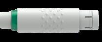
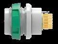
Minimum clearance for ground lug of receptacle.
View from F - Number of contacts (reference)
dimensions and images shown are in millimeters and are for reference only.
UNSHIELDED
Cable Ø range (mm) Use with PEEK Insulators
2.5 - 3.5 E3 105.6/3.5
3.5 - 4.5 E3 105.6/4.5
4.5 - 5.5 E3 105.6/5.5
5.5 - 6.5
6.5 - 7.5
7.5 - 8.5
8.5 - 9.5
- 10.5
For use with unshielded cable or when shield is not carried through connector body.
For use with shielded cable when shield is to be carried through connector body.
For use when sealing shielded or unshielded cable to plug body.
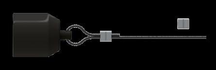
Part number Cap material Stainless steel cable covering material
105.274 (Black) PEI FEP –Teflon®
Crimp ferrule (300.637) is included.
To attach the crimp ferrule to the stainless steel cable, use a crimp tool, a vice or a pair of pliers with parallel jaws. There are no specific Fischer Connectors tools.
Characteristic Product type
Plug (S or SI 405) with sealed cable clamp set and cap
Sealing performance
Receptacle (DBP 405)
Endurance 5,000 mating cycles
OPERATING TEMPERATURE RANGE
Component Material
Body PEI
Insulator PEEK
Plastic Cable Clamp POM (Delrin®)
Cable clamp seal TPE
Cable strain relief TPE
VMQ - Silicone rubber
Sealing cap PEI with FPM O-ring
Metal parts
Parts
Metal parts (except contacts), inner body shell of S plug
Brass
Contacts Male (solder)
CuZn39Pb3 CW614N
UNS C 38500
Nickel SAE-AMS-QQ-N-290
SAE-AMS2404
Brass CuZn39Pb3 CW614N
Bronze CuSn4Zn4Pb4 CW456K
UNS C 38500 1 µm Gold over Nickel
MIL-DTL- 45204D
Type 1 + ASTM B488 Female, male (crimp)
ASTM B 139, UNS C 54400
Plastic Parts
Parts
Body shell, sealing cap, back nut, mounting
in sealing cap
(Viton®)
dimensions and images shown are in millimeters and are for reference only.
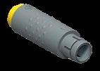
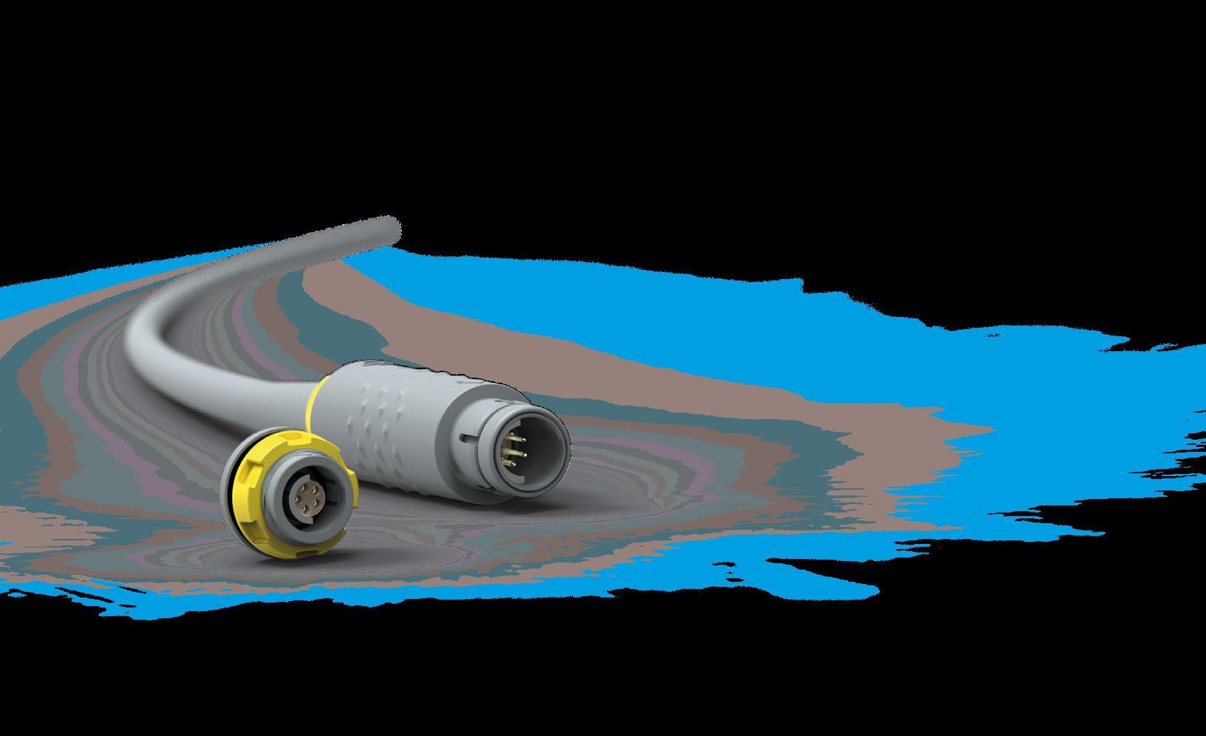
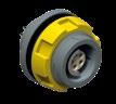
This catalog covers our standard connector solutions. For specific requests, including hybrid or custom connectors, please contact your local sales representative.
BODY STYLE
Locking system
Sealing
Design
Integral shielding SI 4032 Push-pull
P50/ IP68 with cap or mated with DBPO Standard No

BODY STYLES DBP 4032 DBPO 4032
Sealing IP50 IP68
Design Standard Standard
CABLE MOUNTED
SI 4032
BODY STYLE
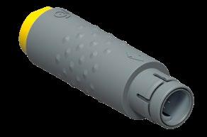
PANEL MOUNTED
DBP / DBPO 4032
BODY STYLES
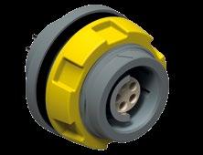
* See contact configurations page B 9-16.
PANEL CUT-OUT
Body style
Plug = SI
Receptacle, rear panel mounted = DBP
Receptacle, rear panel mounted, sealed when mated (IP68) = DBPO
Series 4032
Contact polarity
Plugs have male contacts. Receptacles have female contacts = A
Plugs have female contacts. Receptacles have male contacts. = Z
Contact configuration
See page B9-16
Contact type Solder = J
4032 A 057 Z 7
4032 A 010 Z 10 PEEK 0.7
4032 A 012 Z 12 PEEK 0.7
ø0.79mm AWG21 [1]
[7/30]
[1]
4032 A 019 Z 19 PEEK 0.5 max ø0.43mm AWG26 [1] AWG28 [19/40]
1) Current per contact at 40°C temperature rise measured on the basic curve according to IEC 60512-5-2-5b. For the max. operating current a reduction factor must be used and limitations due to the size of the wires and the permissible upper temperature limit of the materials employed must be taken into account. See page A-12 for details.
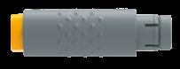
DBP/DBPO 4032
View from F - Number of contacts ( reference )
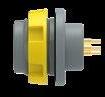
dimensions and images shown are in millimeters and are for reference only.
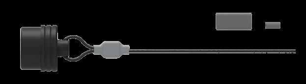
Part number Cap Material Stainless steel cable covering material
4032.703 POM (Delrin®) FEP –Teflon®
Crimp ferrule (300.922) and heat shrink tube (300.930) are included.
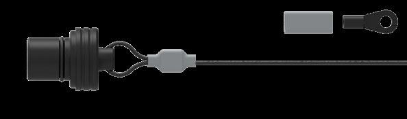
Part number Cap Material Stainless steel cable covering material
4032.701 POM (Delrin®) FEP –Teflon®
Crimp ferrule (300.922), crimp lug (300.299) and heat shrink tube (300.930) are included.
To attach the crimp ferrule or the crimp lug to the stainless steel cable, use a crimp tool, a vice or a pair of pliers with parallel jaws. See page B6-22 for recommended crimping tool for ferrule.
For unshielded and unsealed applications.
For use when sealing shielded or unshielded cable to plug body.
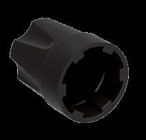
Characteristic
Sealing performance SI plug - with sealed cable clamp - with cap or mated with DBPO
DBPO receptacle Mated with sealed plug or with cap
IP68
IP50
IP68
DBP receptacle IP50
Endurance 5,000 mating cycles
OPERATING TEMPERATURE RANGE
Component Material
Body PBT
Insulator PEEK
O-rings - receptacle NBR
Unshielded cable clamp POM (Delrin®)
Cable clamp seal TPE
Sealing cap for plug POM (Delrin®) with O-ring
Sealing cap receptacle POM (Delrin®) with NBR O-ring
Metal parts (except contacts)
Contacts Male (solder)
CW614N UNS C 38500
Brass CuZn39Pb3 CW614N
Bronze CuSn4Zn4Pb4 CW456K
UNS C 38500 1 µm gold over nickel
Type 1 + ASTM B488 Female, male (crimp)
ASTM B 139, UNS C 54400
Body shell, sealing cap, back nut, mounting nut
Insulator PEEK UL 94 V-O
O-rings on receptacles and sealing caps for receptacles NBR -
O-ring on sealing cap for plug FPM (Viton®) -
Unshielded cable clamps, sealing cap bodies POM (Delrin®) UL 94 HB
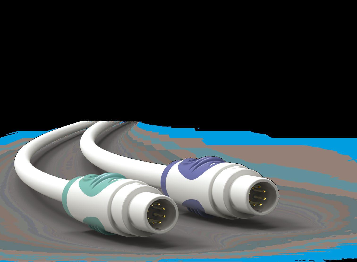
COST-EFFECTIVE | EASY TO USE | MODULAR
Sterilizable (EtO), gamma) Single or two-piece shell
Color-coded for easy integration Lightweight and shock resistant

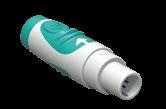
BODY STYLES WHITE BLUE VIOLET TURQUOISE
Locking system Friction Friction Friction Friction
Sealing IP30/ IP40 IP40 IP40 IP40
Design Single/Two-piece shell
BODY STYLES
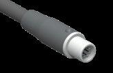
Locking system Friction
Sealing IP65
Design Turnkey
COMPATIBILITY
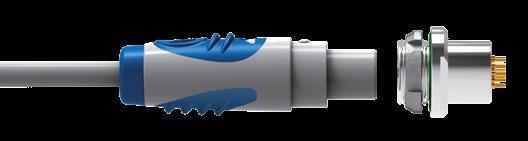
Mateable with all high performance Fischer Connectors’ panel receptacles of the Fischer Core Series Brass 104.
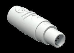
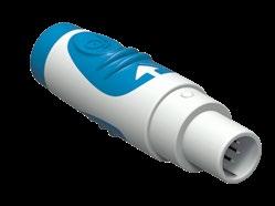
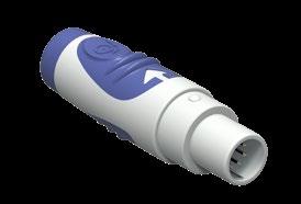
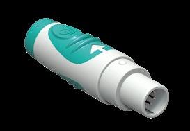
Part Part number Description
Interface
Top shell
Bottom shell
U1 504-A Interface white
U31 504-B01 White top shell
U31 504-A03 White top shell + blue soft touch
U31 504-A04 White top shell + violet soft touch
U31 504-A09 White top shell + turquoise soft touch
U32 504-B01 White bottom shell
U32 504-A03 White bottom shell + blue soft touch
U32 504-A04 White bottom shell + violet soft touch
U32 504-A09 White bottom shell + turquoise soft touch
Ferrule U33 504/5.0 Ferrule Dia 5.0 for two-piece shell version
U34 504-A03 Blue
Bend relief
U34 504-A04 Violet
U34 504-A09 Turquoise
* Assembled with color bend relief.
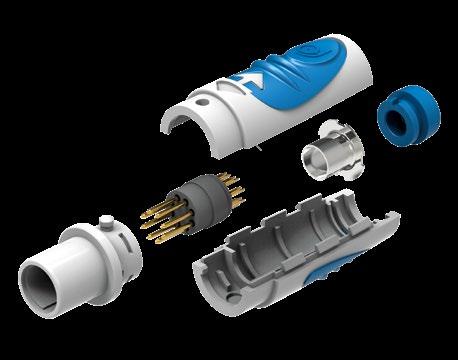
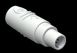
Interface U1 504-A Interface white
Single shell U41 504-A One-piece shell, white only
Ferrule U42 504/5.0 Ferrule Dia 5.0 for single shell version
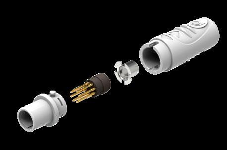
dimensions and images shown are in millimeters and are for reference only.
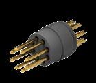
1) Current per contact at 10°C temperature rise measured on the basic curve according to IEC 60512-5-2-5b. For the max. operating current a reduction factor must be used and limitations due to the size of the wires and the permissible upper temperature limit of the materials employed must be taken into account. See page A-12 for details.
MECHANICAL & ENVIRONMENTAL DATA
Sealing rating
– Single shell
– Two-piece shell
IP30
IP40
Operating temperature range -20°C to +65°C
Endurance 10 mating cycles
Gamma irradiation for sterilization
EtO for sterilization
Tested to withstand irradiation up to 60 kGy per ISO 11137-2
Tested with a standard EtO sterilization cycle per ISO 11135
Mating / Unmating force Typ. 10-20 N
MATERIAL & SURFACE TREATMENTS
Contacts Brass or Bronze Gold over Nickel

A pioneer in high-reliability and rugged connector technology, Fischer Connectors has kept the spirit of innovation alive for more than 60 years. Since 1954, it has been reimagining connectivity, turning its customers’ challenges into success stories through breakthrough technologies, high-quality products and highly responsive customer service.
Fischer Connectors helps its customers around the world produce innovative and reliable applications by designing, manufacturing and distributing high-performance, rugged connectivity solutions that withstand the most demanding environments. Its high-quality solutions are particularly suited to applications requiring faultless precision, durability and resistance to extreme conditions, including defense and security, medical, industrial, instrumentation, audiovisual, transportation, and energy.
Headquartered in Saint-Prex, Switzerland (Canton of Vaud), where its R&D Center and manufacturing facilities are also located, the Fischer Connectors Group has cable assembly sites in EMEA, the United States and Asia. The Group also includes local subsidiaries and a wide network of distributors and agents all over the world.
Since 1954, we have grown from a provider of connectors to a global partner in connectivity for our customers. We have expanded to meet market demand, providing a range of tailored connectivity solutions that not only meet our customers’ needs, but that also have the potential to shape the future. Thank you for joining us on this adventure to reimagine connectivity, together.
Jonathan Brossard, Group CEO
Save as expressly provided otherwise, any technical data provided by Fischer Connectors in this document, in hardcopy or electronic form, shall be provided for information purposes only. In no event may Fischer Connectors be bound by or liable (including in case of errors) for any technical data contained in this document, in hardcopy or electronic form, unless such technical data is expressly guaranteed by Fischer Connectors.
The values provided in this document are measured under standard environmental conditions. Applications in non-standard environmental conditions may require additional testing and values may vary from those listed.
Fischer Connectors shall not be liable for damages to the products or services resulting from assembly process, installation or testing performed by the purchaser or any third party upon the purchaser’s request, or damages due to other action or process performed on the products or services by the purchaser or any third party upon the purchaser’s request which fails to comply with Fischer Connectors’ instructions or which are otherwise beyond Fischer Connectors’ control. Fischer Connectors shall not be liable for any defect or failure of Fischer Connectors’ products or services which operate in accordance with specifications, illustrations, descriptions or other particulars due to combination or use of Fischer Connectors’ products or services with any incompatible equipment or product of a third party.
Refer to www.fischerconnectors.com for the General Terms and Conditions of Fischer Connectors.
06.2023 3.5
06.2023 3.5
B1-10 Addition of configurations 1031-15, 1031-29, 104-104
B2-29, B2-31 Addition of configurations 1031-15, 1031-29, 104-104
06.2023 3.5 B7-24 Stainless steel caps for receptacles: correction of part numbers
09.2023
3.6
B1-10, B1-11 Addition of configurations 1031-105, 104-130, 104-131, 104-135 09.2023 3.6 B2-29 - B2-33 Addition of configurations 1031-105, 104-130, 104-131, 104-135 09.2023 3.6 B10-5 Modifications to the Cable Solutions section
09.2023 3.6 B10-6 Table modifications, addition of references A 37 and A 87
10.2023 3.7
B2-29 - B2-33 Adding data for configurations 1031-105, 104-130, 104-131, 104-135
B3-6 New remark about the availability of the WSO body style.
3.8 B2-28, B7-13, B8-13 Modification of contact type for conficguration 103-062 02.2024 3.8 B9-12 - B9-14 Correction on body style plug designation
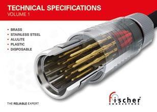

Headquarters
FISCHER CONNECTORS SA
Ch. du Glapin 20 1162 Saint-Prex - Switzerland
Phone +41 21 800 95 95
Free phone +41 800 800 008
www.fischerconnectors.com mail@fischerconnectors.ch
United States, Canada & South America
FISCHER CONNECTORS, Inc.
Atlanta, GA
Phone +1 678 393 5400
Toll free : 800 551 0121
www.fischerconnectors.com/us mail@fischerconnectors.com
France
FISCHER CONNECTORS Sarl
Chanteloup-en-Brie
Phone +33 1 5578 2578
Appel gratuit : 0 800 590 444
www.fischerconnectors.fr mail@fischerconnectors.fr
Germany, Austria & Eastern Europe
FISCHER CONNECTORS GmbH
Zorneding
Phone +49 8106 37722 0
Gebührenfrei : 0 800 233 3233
www.fischerconnectors.de mail@fischerconnectors.de
Italy
FISCHER CONNECTORS Srl
Monza
Phone +39 039 734 072
www.fischerconnectors.it mail@fischerconnectors.it
United Kingdom & Ireland
FISCHER CONNECTORS Ltd.
Waterlooville, Hampshire
Phone +44 23 9245 9600
Toll free : 0 800 432 0301
www.fischerconnectors.co.uk
sales@fischerconnectors.co.uk
India
FISCHER CONNECTORS India Pvt. Ltd.
504 GF& FF , Pace City 2 Sector 37
Gurugram 122004
Haryana
Phone +91 (0)124 5063725
www.fischerconnectors.com
salesin@fischerconnectors.in
Asia
FISCHER CONNECTORS ASIA Ltd
Hong Kong
Phone +852 2620 6118
www.fischerconnectors.hk
mail@fischerconnectors.hk Japan
FISCHER CONNECTORS K.K
Tokyo
Phone +81 70 1056 6637
www.fischerconnectors.jp
mail@fischerconnectors.jp