CHAPTER


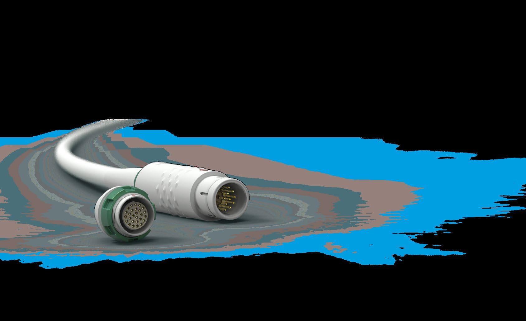
EASY TO USE | DURABLE | LIGHTWEIGHT
Sealed up to IP68
Over 5,000 mating cycles
Resistant to large temperarure variations Color coding for easy operation
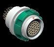
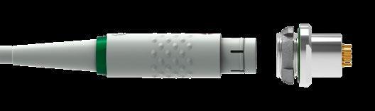
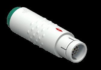
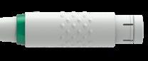
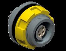
PLUGS CABLE MOUNTED
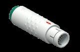
BODY STYLES S 405 SI 405
Locking system Push-pull Push-pull
Sealing IP50/ IP67 IP50/ IP67
Design Standard Standard
Integral shielding Yes No
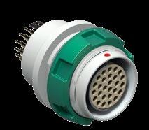
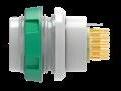
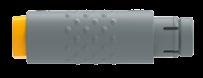
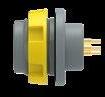
BODY STYLE DBP 405
Sealing IP50
Design Standard
COMPATIBILITY
dimensions and images shown are in millimeters and are for reference only.
Mateable with all high performance Fischer Connectors’ panel receptacles of the Fischer Core Series Brass 105.
CABLE MOUNTED
S/SI 405 BODY STYLES
PANEL MOUNTED
DBP 405 BODY STYLE
* See contact configurations page B 9-6.
PANEL CUT-OUT
Figure 1
All dimensions and images shown are in millimeters and are for reference only.
Example:
Body style
S = Plug, with integral shielding
SI = Plug, without integral shielding
DBP = Receptacle, rear panel mounted
Series
405
Contact polarity
A = Plugs have male contacts. Receptacles have female contacts.
Z = Plugs have female contacts. Receptacles have male contacts.
Contact configuration
See page B 9-6
Body color
B = Beige
C = Anthracite
Insulator material
3 = PEEK
Contact type
J = Solder
K = Crimp
L = PCB
Color coding
2 = Anthracite
3 = Green
4 = Blue
5 = Yellow
8 = Beige
Bend relief material
R = None
S = Silicone (6.5 dia.)
T = TPE (6.5 dia.)
U = Silicone (3.5 dia.)
W= TPE (3.5 dia.)
Standard options
1) Current per contact at 40°C temperature rise measured on the basic curve according to IEC 60512-5-2-5b. For the max. operating current a reduction factor must be used and limitations due to the size of the wires and the permissible upper temperature limit of the materials employed must be taken into account. See page A-12 for details.
S/SI 405 DBP 405
BODY STYLES
Minimum clearance for ground lug of receptacle.
View from F - Number of contacts (reference)
dimensions and images shown are in millimeters and are for reference only.
UNSHIELDED
Cable Ø range (mm) Use with PEEK Insulators
2.5 - 3.5 E3 105.6/3.5
3.5 - 4.5 E3 105.6/4.5
4.5 - 5.5 E3 105.6/5.5
5.5 - 6.5
6.5 - 7.5
7.5 - 8.5
8.5 - 9.5
- 10.5
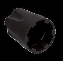
For use with unshielded cable or when shield is not carried through connector body.
For use with shielded cable when shield is to be carried through connector body.
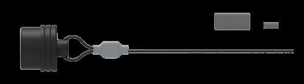
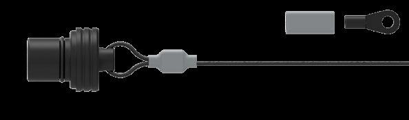
For use when sealing shielded or unshielded cable to plug body.

Part number Cap material Stainless steel cable covering material
105.274 (Black) PEI FEP –Teflon®
Crimp ferrule (300.637) is included.
To attach the crimp ferrule to the stainless steel cable, use a crimp tool, a vice or a pair of pliers with parallel jaws. There are no specific Fischer Connectors tools.
Characteristic Product type
Plug (S or SI 405) with sealed cable clamp set and cap
Sealing performance
Receptacle (DBP 405)
Endurance 5,000 mating cycles
OPERATING TEMPERATURE RANGE
Component Material
Body PEI
Insulator PEEK
Plastic Cable Clamp POM (Delrin®)
Cable clamp seal TPE
Cable strain relief TPE
VMQ - Silicone rubber
Sealing cap PEI with FPM O-ring
Metal parts
Parts
Metal parts (except contacts), inner body shell of S plug
Brass
Contacts Male (solder)
CuZn39Pb3 CW614N
UNS C 38500
Nickel SAE-AMS-QQ-N-290
SAE-AMS2404
Brass CuZn39Pb3 CW614N
Bronze CuSn4Zn4Pb4 CW456K
UNS C 38500 1 µm Gold over Nickel
MIL-DTL- 45204D
Type 1 + ASTM B488 Female, male (crimp)
ASTM B 139, UNS C 54400
Plastic Parts
Parts
Body shell, sealing cap, back nut, mounting
in sealing cap
(Viton®)
dimensions and images shown are in millimeters and are for reference only.
This catalog covers our standard connector solutions. For specific requests, including hybrid or custom connectors, please contact your local sales representative.
BODY STYLE
Locking system
Sealing
Design
Integral shielding SI 4032 Push-pull
P50/ IP68 with cap or mated with DBPO Standard No

BODY STYLES DBP 4032 DBPO 4032
Sealing IP50 IP68
Design Standard Standard
CABLE MOUNTED
SI 4032
BODY STYLE
PANEL MOUNTED
DBP / DBPO 4032
BODY STYLES
* See contact configurations page B 9-16.
PANEL CUT-OUT
Body style
Plug = SI
Receptacle, rear panel mounted = DBP
Receptacle, rear panel mounted, sealed when mated (IP68) = DBPO
Series 4032
Contact polarity
Plugs have male contacts. Receptacles have female contacts = A
Plugs have female contacts. Receptacles have male contacts. = Z
Contact configuration
See page B9-16
Contact type Solder = J
4032 A 057 Z 7
4032 A 010 Z 10 PEEK 0.7
4032 A 012 Z 12 PEEK 0.7
ø0.79mm AWG21 [1]
[7/30]
[1]
4032 A 019 Z 19 PEEK 0.5 max ø0.43mm AWG26 [1] AWG28 [19/40]
1) Current per contact at 40°C temperature rise measured on the basic curve according to IEC 60512-5-2-5b. For the max. operating current a reduction factor must be used and limitations due to the size of the wires and the permissible upper temperature limit of the materials employed must be taken into account. See page A-12 for details.
DBP/DBPO 4032
View from F - Number of contacts ( reference )
dimensions and images shown are in millimeters and are for reference only.

Part number Cap Material Stainless steel cable covering material
4032.703 POM (Delrin®) FEP –Teflon®
Crimp ferrule (300.922) and heat shrink tube (300.930) are included.
Part number Cap Material Stainless steel cable covering material
4032.701 POM (Delrin®) FEP –Teflon®
Crimp ferrule (300.922), crimp lug (300.299) and heat shrink tube (300.930) are included.
To attach the crimp ferrule or the crimp lug to the stainless steel cable, use a crimp tool, a vice or a pair of pliers with parallel jaws. See page B6-22 for recommended crimping tool for ferrule.
For unshielded and unsealed applications.
For use when sealing shielded or unshielded cable to plug body.
Characteristic
Sealing performance SI plug - with sealed cable clamp - with cap or mated with DBPO
DBPO receptacle Mated with sealed plug or with cap
IP68
IP50
IP68
DBP receptacle IP50
Endurance 5,000 mating cycles
OPERATING TEMPERATURE RANGE
Component Material
Body PBT
Insulator PEEK
O-rings - receptacle NBR
Unshielded cable clamp POM (Delrin®)
Cable clamp seal TPE
Sealing cap for plug POM (Delrin®) with O-ring
Sealing cap receptacle POM (Delrin®) with NBR O-ring
Metal parts (except contacts)
Contacts Male (solder)
CW614N UNS C 38500
Brass CuZn39Pb3 CW614N
Bronze CuSn4Zn4Pb4 CW456K
UNS C 38500 1 µm gold over nickel
Type 1 + ASTM B488 Female, male (crimp)
ASTM B 139, UNS C 54400
Body shell, sealing cap, back nut, mounting nut
Insulator PEEK UL 94 V-O
O-rings on receptacles and sealing caps for receptacles NBR -
O-ring on sealing cap for plug FPM (Viton®) -
Unshielded cable clamps, sealing cap bodies POM (Delrin®) UL 94 HB