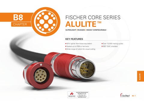
Fischer Connectors Core Series Alulite Technical Catalogue

Page 1


CHAPTER

CABLE MOUNTED

BODY STYLES S SC SS SSC

Locking system Push-pull Quick-release Push-pull Quick-release

Sealing IP50/ IP68 IP50/ IP68 IP50/ IP68

IP50/ IP68

Design Standard Standard Short/Overmolding Short/Overmolding

PLUGS* RECEPTACLES*

PANEL FRONT MOUNTED

BODY STYLES D DEU DEE

Sealing IP50 IP68 Hermetic

Design Rear-projecting Rear-projecting

PANEL REAR MOUNTED

BODY STYLES DBPU DBPE DBPLU DBPLE

Sealing IP68 Hermetic IP68 Hermetic

Design Rear-projecting Front-projecting

*See full color selection in part numbering sections (pages B 8-6 B 8-9, B 8-11).

All dimensions and images shown are in millimeters and are for reference only.

PLUGS

CABLE MOUNTED

Body style

Protection

Locking system

Contacts

Design

Cabling

Unsealed (IP50)

Sealed up to IP68

Push-pull

Quick-release

Crimp

Solder

Colored housing

Shortened body

Cable clamp sets

Overmoldable

Heat shrinkable

Other body styles available on request.

References to detailed information

Sealing categories, page A-6

Locking systems, page A-5

Electrical & contact configurations, page B8-12

Body styles, page B8-3

Cable clamp sets, page B 2-39

Technical dimensions

PLUGS CABLE MOUNTED

BODY STYLES

1) Weight shown is without cable clamp set, overmolding or heat shrinking.

2) Max. cable diameter below shield.

All dimensions and images shown are in millimeters and are for reference only.

STYLES

PLUGS

The configurator is designed for multipole contact blocks only. For coax or triax blocks, please contact us.

AL = Aluminum

Housing treatment Housing material

1231 = Black (chromium)

1411 = Blue (anodized)

1611 = Red (anodized)

1731 = Grey (chromium)

S = Standard body length

SS = Shortened body length

If standard automatic push-pull locking system is desired, leave field blank.

Other option possible : C = Clic Loc, quick-release

102, 103, 1031, 104, or 105 = Series

(See dimensions page B8-5)

For standard body length plugs (S) :

11 =Standard clamp nut, no bend relief.

(See pages B 8-19 to B 8-24)

For shortened body length plugs (SS) :

13 = For heat shrinking / boots

14 = For injection / overmolding

Keying code

11 = Code 1

12 = Code 2

13 = Code 3

= Solder CP = Crimp Three-digit

(see pages B 8-12 to B8 -18)

A = Male contacts on plug

Z = Female contacts on plug

1) Fischer Connectors cannot be held liable for small color variations that may appear from one batch to another.

Example 1

AL1231-S-103-A062SR11-11 Example 2

AL1231-S-103-A053SR11-11 AL1731-SS-102-A056SR12-13

RECEPTACLES

PANEL MOUNTED

Body Style

Protection

Unsealed (IP50)

Sealed up to IP68

Hermetic

Crimp

Contacts

Solder

PCB

Colored housing

Design

Assembly

Flush

Front-projecting

Front-mounting

Rear-mounting

Other body styles available on request.

All dimensions and images shown are in millimeters and are for reference only.

References to detailed information

Sealing categories, page A-6

Electrical & contact configurations, page B8-12

Body styles, chapter B8-3

RECEPTACLES

PANEL FRONT MOUNTED

BODY STYLES

DEU/DEE

STYLES

RECEPTACLES

PANEL FRONT MOUNTED

The configurator is designed for multipole contact blocks only.

For coax or triax blocks, please contact us.

AL = Aluminum

1231 = Black (chromium) 1411 = Blue (anodized) 1611 = Red (anodized) 1731 = Grey (chromium)

D = Flush (vs. panel) Front-mounting receptacle

If no sealing level is desired, leave field blank. Other options possible :

EU = Sealed (IP68) even unmated

SPACERS FOR DEU/DEE BODY STYLES OF THE 102 SERIES

EE = Hermetic 102, 103, 1031, 104, or 105 = Series (See dimensions section)

1) Fischer Connectors can not be held liable for small color variations that may appear from one batch to another.

= Yes

= Hexagonal

12 = None

= No

If ‘No sealing level‘ chosen in section BC, leave field blank.

Options possible if you selected ‘Sealed (IP68) even unmated‘ or ‘Hermetic‘ :

11 = Viton

12 = EPDM (low temperature)

11 = Code 1

12 = Code 2

13 = Code 3

Options possible if no sealing level is required:

SR = Solder

CP =Crimp "D" only

PB = PCB

Options possible if selected sealing level is ‘Sealed (IP68) even unmated’ or ‘Hermetic’ :

SR = Solder

PB = PCB

Three-digit number (see pages B 8-12 to B8 -18)

A = Female contacts on receptacle

Z = Male contacts on receptacle

RECEPTACLES

PANEL REAR MOUNTED

DBPU/DBPE BODY STYLES

1) Weight includes nut.

2) Pin length and diameter vary according to contact configuration. Contact us for more information.

3) For information on nutdrivers ( ), see Tooling page B 8-29.

PANEL CUT OUT

BODY STYLES

* – Pin for PCB contacts versions; all Series.

– Tag for solder contact versions; Series 103 to 107. – Barrel for solder contact versions; Series 102.

PANEL CUT OUT

Fig.

RECEPTACLES

PANEL REAR MOUNTED

The configurator is designed for multipole contact blocks only. For coax or triax blocks, please contact us.

= Aluminum

Housing treatment

1231 = Black (chromium) 1411 = Blue (anodized) 1611 = Red (anodized) 1731 = Grey (chromium)

DBP = Flush (vs. panel) Rear-mounting receptacle

DBPL = Front-projecting (vs. panel) Rear-mounting receptacle

U= Sealed (IP68) even unmated

Example 1:

AL1231-DBPLU-102-A059PB12-12G13

Example 2:

AL1231-DBPLE-102-Z054SR11-11G13

E = Hermetic 102, 103, 1031, 104 or 105 = Series (See dimensions section)

1) Fischer Connectors can not be held liable for small color variations that may appear from one batch to another.

dimensions and images shown are in millimeters and are for reference only.

102 SERIES

1) Wire gauge stranding values are in brackets.

2) For a given AWG, the diameter of some stranded conductor designs could exceptionally be larger than the hole diameter of the barrel. Testing may be required.

3) Current per contact at 40°C temperature rise measured on the basic curve according to IEC 60512-5-2-5b. For the max. operating current a reduction factor must be used and limitations due to the size of the wires and the permissible upper temperature limit of the materials employed must be taken into account. See page A-12 for details.

4) Recommended operating voltage at sea level measured according to IEC 60664-1.

5) Measured with S plug and D receptacle.

6) Plug with crimp contacts must be used with unshielded clamps only.

7) Only available for A polarity plugs.

Electrical & contact configurations

103 & 1031 SERIES

1031A 012 Z 12

1031A 019 Z 19

1) Wire gauge stranding values are in brackets.

[1]

[19/40]

2) For a given AWG, the diameter of some stranded conductor designs could be larger than the hole diameter of the barrel. Testing maybe required.

3) Current per contact at 40°C temperature rise measured on the basic curve according to IEC 60512-5-2-5b. For the max. operating current a reduction factor must be used and limitations due to the size of the wires and the permissible upper temperature limit of the materials employed must be taken into account. See page A-12 for details.

4) Recommended operating voltage at sea level measured according to IEC 60664-1.

5) Measured with S plug and D receptacle.

1) Stranding values are in brackets.

2) For a given AWG, the diameter of some stranded conductor designs could be larger than the hole diameter of the barrel. Testing may be required.

3) Current per contact at 40°C temperature rise measured on the basic curve according to IEC 60512-5-2-5b. For the max. operating current a reduction factor must be used and limitations due to the size of the wires and the permissible upper temperature limit of the materials employed must be taken into account. See page A-12 for details.

4) Recommended operating voltage at sea level measured according to IEC 60664-1.

5) Test voltages between the contacts with the shortest distance.

6) Measured with S plug and D receptacle.

Electrical & contact configurations

104 SERIES

[1]

[7/30]

A124 5)

1) Stranding values are in brackets.

2) For a given AWG, the diameter of some stranded conductor designs could exceptionally be larger than the hole diameter of the barrel. Testing may be required.

3) Current per contact at 40°C temperature rise measured on the basic curve according to IEC 60512-5-2-5b. For the max. operating current a reduction factor must be used and limitations due to the size of the wires and the permissible upper temperature limit of the materials employed must be taken into account. See page A-12 for details.

4) Recommended operating voltage at sea level measured according to IEC 60664-1.

5) Solder and PCB contact types available only for DBPU and DBPLU receptacles. Crimp contact type available only for plugs.

6) Measured with S plug and D receptacle.

105 SERIES

= Standard = Option

1) Stranding values are in brackets.

2) For a given AWG, the diameter of some stranded conductor designs could exceptionally be larger than the hole diameter of the barrel. Testing may be required.

3) Current per contact at 40°C temperature rise measured on the basic curve according to IEC 60512-5-2-5b. For the max. operating current a reduction factor must be used and limitations due to the size of the wires and the permissible upper temperature limit of the materials employed must be taken into account. See page A-12 for details.

4) Recommended operating voltage at sea level measured according to IEC 60664-1.

5) Contact dia. 2.0 is positioned to make contact first and break last.

6) Measured with S plug and D receptacle.

Electrical & contact configurations

105 SERIES

1) Stranding values are in brackets.

2) For a given AWG, the diameter of some stranded conductor designs could exceptionally be larger than the hole diameter of the barrel. Testing may be required.

3) Current per contact at 40°C temperature rise measured on the basic curve according to IEC 60512-5-2-5b. For the max. operating current a reduction factor must be used and limitations due to the size of the wires and the permissible upper temperature limit of the materials employed must be taken into account. See page A-12 for details.

4) Recommended operating voltage at sea level measured according to IEC 60664-1.

5) Contacts dia. 1.3 are positioned to make contact first and break last.

6) Contacts dia. 1.6 are positioned to make contact first and break last.

7) Inverted polarity: female contacts on plug/male contact on receptacle

8) Measured with S plug and D receptacle.

CONTACT TYPES

CRIMP CONTACTS

Selectively annealed area

Special tools required

Limited range of wire sizes

TOOLING FOR CRIMP CONTACTS

Each contact has a selectively annealed area which is crushed during assembly by specialized tooling to ensure proper termination of the wire to the contact.

Commonly used for field termination or repair, as no soldering is required.

Not available for sealed or hermetic connectors.

See section Tooling, section B 6-21, for description of Crimping Tool and Positioner.

Please refer to www.fischerconnectors.com/technical for detailed information and assembly instructions.

Cable

CABLE CLAMP SETS

To guarantee excellent cable retention and strain relief, Fischer Connectors provides robust and high quality cable clamp sets :

Collet style clamp system retains cable over large jacket surface area.

Protection of small diameters and delicate conductors.

Can be combined with cable bend reliefs for optimal performance.

Cable clamp sets are used with cable mounted connectors, except SS/SSC which require overmolding or heat shrinking techniques.

RANGE OVERVIEW : S, U & E CABLE CLAMP SETS

Fischer Connectors offers three types of cable clamps sets.

The table below will help you select the one corresponding to your needs.

Do you need the interface between the cable and the connector to be sealed ?

Cable clamp set

S - Shielded

U - Unshielded

E - Environmental

PART NUMBERING

Cable clamp sets are ordered separately

Multipole low voltage

AL1731-S-102-A056SR11-11

Examples connector ordering line

AL1731-S-102-A056SR11-11

Clamp set ordering line

E3 102.5/2.0

See following pages for cable clamp set selection.

Do you need the connector to be terminated to the cable shield ?

102 SERIES

Shielded cable clamp with sleeve and clamp.

UNSHIELDED

Unshielded, one-piece cable clamp.

ENVIRONMENTAL

Environmentally sealed clamp for use with shielded or unshielded cables.

103 SERIES

S

SHIELDED Shielded cable clamp with sleeve and clamp.

UNSHIELDED

Unshielded, one-piece cable clamp. E

ENVIRONMENTAL

Environmentally sealed clamp for use with shielded or unshielded cables.

dimensions and images shown are in millimeters and are for reference only.

1031 SERIES

Shielded cable clamp with sleeve and clamp.

UNSHIELDED

Unshielded, one-piece cable clamp.

ENVIRONMENTAL

Environmentally sealed clamp for use with shielded or unshielded cables.

104 SERIES

S SHIELDED

Shielded cable clamp with sleeve and clamp. U UNSHIELDED

Unshielded, one-piece cable clamp.

E

ENVIRONMENTAL

Environmentally sealed clamp for use with shielded or unshielded cables.

105 SERIES

Shielded cable clamp with sleeve and clamp.

UNSHIELDED

Unshielded, one-piece cable clamp.

ENVIRONMENTAL

Environmentally sealed clamp for use with shielded or unshielded cables.

Crimp ferrule, crimp lug and heat shrink tube have to be ordered separately. Material: Cap: SantopreneTM TPV 101-80 / Cord: Polyester.

SOFT CAPS - LANYARD WITH POLYESTER CORD FOR RECEPTACLES FOR PLUGS

SOFT CAPS - ONE-PIECE

FOR RECEPTACLES FOR PLUGS

SOFT CAPS - LANYARD WITH STAINLESS STEEL CABLE

FOR PLUGS

Crimp ferrule (300.922) and heat shrink tube (300.930) are included. Material: Cap: SantopreneTM TPV 101-80 Cable: Stainless steel with FEP-Teflon® covering

FOR RECEPTACLES

SOFT

CAPS - LANYARDS WITH STAINLESS STEEL CABLE (PRE-ASSEMBLED)

FOR RECEPTACLES

Cap: SantopreneTM TPV 101-80

Cable: stainless steel with FEP-Teflon® covering Fixing lug: black chrome plated brass (ISO CuZn37)

Crimp ferrule, heat shrink tube and fixing lug are included and mounted.

NUT DRIVER FOR SLOTTED NUTS

NUT DRIVER WITH T-HANDLE AND HEX DRIVE

FOR

DECORATIVE SLOTTED NUTS

Thread

M9x0.5 15 TC00.000

M10x0.5 16 TC00.007

M14x1 21 TG00.001

M15x1 22 TK00.000

M16x1 23 TK00.002

M20x1 28 TP00.005

Material: hardened tool steel, nickel plated.

dimensions and images shown are in millimeters and are for reference only.

MECHANICAL & ENVIRONMENTAL DATA

Parameter

Mating cycles

Operating temperature range

- Viton O-ring at plug interface

- EPDM O-ring (Low temp) at plug interface

Sealing

Hermeticity

- DEE, DBPE, DBPLE

Vibration

10,000

-20°C to +200°C

-50°C to +160°C

See details on page A-9 and B8-32

IP68 ; 2m submersion for 24 hours

Hermetic: Tested: <10-8 mbar l/s

IP69

Contact interruption < 1µs (10-2000Hz/15G)

ELECTRICAL DATA*

Parameter

Grounding resistance1) (shell-to-shell) Typical 50 mΩ

EMC shielding 360-degree EMC shielding

1) IEC 60512-2-6-2f

* Please refer to contact block sections for detailed information.

Standard

IEC 60512-9-1

EIA-364-09

IEC 60068-2-14

IEC 60529

IEC 60068-2-17 test Qk method 3, alternative b IEC 60529

MIL-STD-202 Method 204, Condition B

MATERIAL & SURFACE TREATMENTS

Plug housing

- Body

- Latching sleeve

Receptacle housing

- Receptacle housing (anodized)

Grounding

- Tag (solder and crimp contacts)

- Pin (PCB contacts)

Contacts

- Male contacts

- Female contacts

Brass

or Brass

Bronze

Aluminum is not recommended for marine or corrosive environments. In this case, we recommend the Fischer Core Series Brass or Core Series Stainless Steel.

Insulator and sealing

Contact blocks and other insulators for our standard connectors are manufactured from high performance engineering plastic materials. The standard materials of each connector series are listed under Electrical & Contact configurations in pages B 8-12 through B 8-18. Ceramics and other dielectrics are available on special order.

Insulator and sealing International symbol Flammability

Insulator PEEK - PTFE - PBT

94 V-O

Interface O-rings (receptacles) FPM (Viton ®) / EPDM -

Sealant material - IP68 (receptacles) - Hermetic Silicon compound Epoxy compound

Our products are RoHs compliant and conform with the EC Directives 2002/95/EC.

94 V-O

94 HB

OPERATING TEMPERATURES

The temperature ranges quoted by the manufacturers of the plastic materials are usually the absolute maximum values. When exposed to the mechanical and electrical stresses present in a connector, these values are often unrealistic. If a composite connector system including accessories is used, then the item with the lowest temperature performance will dictate the operating temperature limit of the system. The table below shows our recommended operating temperature ranges.

1

2

7

8

Turn static files into dynamic content formats.

Create a flipbook
Issuu converts static files into: digital portfolios, online yearbooks, online catalogs, digital photo albums and more. Sign up and create your flipbook.
Fischer Connectors Core Series Alulite Technical Catalogue by Rojone Pty Ltd - Issuu