
CHAPTER FISCHER FIBEROPTIC SERIES
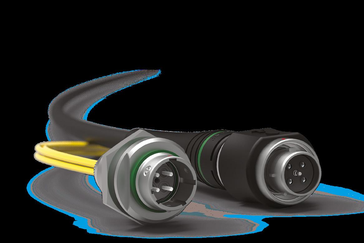
FIBEROPTIC
PLUGS

RECEPTACLES


FOR ALL FIBEROPTIC
For specific requests, including hybrid or custom connectors, please contact your local sales representative.
Configuration matrix
PLUGS & RECEPTACLES
dimensions and images shown are
PLUGS

Body style
Protection
Locking system
Unsealed (IP50)
Sealed up to IP68
Friction
Push-pull
Quick-release
Lanyard
Tamperproof
Fiber optic termini
Termination
Housing color
Design
Rear Accessories2)
Electrical solder contacts1)
Natural chrome
Shortened body
Straight
Right-angle
Wire sets
Cable clamp set
Potting set
Cable bend reliefs
Accessories
Protective sleeves
Soft caps
FO1
Size
1) FOH only.
FO2/FO4
FOH
2) Please refer to configurations matrix on page I-3.
References to detailed information
Sealing categories, page A-6
Locking systems, page A-5
Fiber type and pin layout, page I- 30
Technical information, page I -29
Rear Accessories, pages I -5 to I-7
Accessories, page I -25
Technical dimensions, pages I-5 to I-7
For more information visit our website www.fischerconnectors.com/technical
Technical dimensions
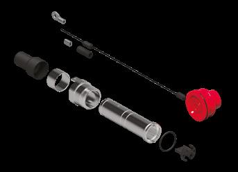
CABLE MOUNTED
BODY STYLE PLUGS - FO1

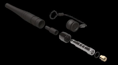
REAR ACCESSORIES
CABLE CLAMP SET

1) The last number indicates the max compatible cable diameter in mm.
Note: indicated connector P/N = delivered without contact, termini and rear accessory
All dimensions and images shown are in millimeters and are for reference only.
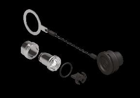
FO1 P01LGR1 00A00 A 000 FO1 - P01 Plug
FO1 P01 CABLE CLAMP SET L36 D3.5 1) FO1 - P01 Plug cable clamp set
FO1 P01 POTTING SET L41 D3.5 1) FO1 - P01 Plug potting set
POTTING SET
MOUNTED
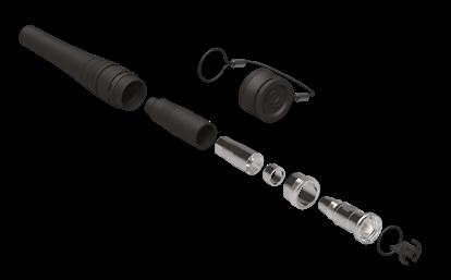
BODY STYLE PLUGS - FO2/FO4

REAR ACCESSORIES
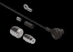
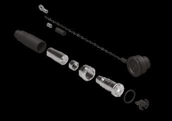
FO2 P01LGR1 00A00 A 000 FO2 - P01 Plug
FO4 P01LGR1 00A00 A 000 FO4 - P01 Plug
FO2-4 P01 CABLE CLAMP SET L49 D6 1) FO2/FO4 - P01 Plug cable clamp set
FO2-4 P01 POTTING SET L49 D6.5 1) FO2/FO4 - P01 Plug potting set
FO2-4 P01 POTTING SET L54 D10.8 1) FO2/FO4 - P01 Plug potting set
CABLE CLAMP SET POTTING SET

1) The last number indicates the max compatible cable diameter in mm.
Note: indicated connector P/N = delivered without contacts, termini and rear accessory
Technical dimensions
PLUGS - FOH
CABLE MOUNTED
STYLE

REAR ACCESSORIES POTTING SET

1) The last number indicates the max compatible cable diameter in mm.
Note: indicated connector P/N = delivered without contacts, termini and rear accessory
dimensions and images shown are in millimeters and are for reference only.
P01LGR1 00A00 A 000 FOH - P01 Plug
P01 POTTING SET L54 D10.8 1) FOH - P01 Plug potting set
RECEPTACLES
CABLE MOUNTED
Body style
Protection

Unsealed (IP50)
Sealed up to IP68
Friction
Push-pull
Locking system
Quick-release
Lanyard
Tamperproof
Fiber optic termini
Termination
Electrical solder contacts1)
Housing color Natural chrome
Shortened body
Design
Straight
Right-angle
Wire sets
Rear Accessories1)
Cable clamp set
Potting set
Cable bend reliefs
Accessories
Protective sleeves
Soft caps
FO1
Size
FO2/FO4
FOH
1) Please refer to configurations matrix on page I-3.
References to detailed information
Sealing categories, page A-6
Locking systems, page A-5
Fiber type and pin layout, page I- 30
Technical information, page I -29
Rear accessories, pages I -9 to I-11
Accessories, page I -25
Technical dimensions, page I-9 to I-11
For more information visit our website www.fischerconnectors.com/technical
CABLE MOUNTED R50 BODY STYLE RECEPTACLES
- FO1

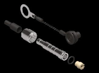
REAR ACCESSORIES
CABLE CLAMP SET

1) The last number indicates the max compatible cable diameter in mm.
Note: indicated connector P/N = delivered without contact, termini and rear accessory
and
FO1 R50LGR1 00A00 A 000 FO1 - R50 Receptcale
FO1 R50 CABLE CLAMP SET L36 D3.5 1) FO1 - R50 Receptacle cable clamp set
FO1 R50 POTTING SET L41 D3.5 1) FO1 - R50 Receptacle potting set
POTTING SET

RECEPTACLES - FO2/FO4
CABLE MOUNTED R50 BODY STYLE

REAR ACCESSORIES
FO2 R50LGR1 00A00 A 000 FO2 - R50 Receptacle
FO4 R50LGR1 00A00 A 000 FO4 - R50 Receptacle
FO2-4 R50 CABLE CLAMP SET L49 D6 1) FO2/FO4 - R50 Receptacle cable clamp set
FO2-4 R50 POTTING SET L49 D6.5 1) FO2/FO4 - R50 Receptacle potting set
FO2-4 R50 POTTING SET L54 D10.8 1) FO2/FO4 – R50 Receptacle potting set
CABLE CLAMP SET POTTING SET


1) The last number indicates the max compatible cable diameter in mm.
Note: indicated connector P/N = delivered without contacts, termini and rear accessory
RECEPTACLES - FOH
CABLE MOUNTED R50 BODY STYLE

POTTING SET

1) The last number indicates the max compatible cable diameter in mm.
Note: indicated connector P/N = delivered without contact, termini and rear accessory
dimensions and images shown are in millimeters and are for reference only.
ø24
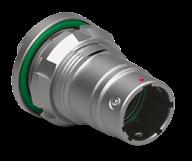
FOH R50LGR1 00A00 A 000 FOH - R50 Receptacle
FOH R50 POTTING SET L54 D10.8 1) FOH - R50 Receptacle potting set
RECEPTACLES
PANEL MOUNTED
Body style
Protection


Unsealed (IP50)
Sealed up to IP68
Friction
Push-pull
Locking system
Quick-release
Lanyard
Tamperproof
Fiber optic termini
Termination
Electrical solder contacts1)
Housing color Natural chrome
Shortened body
Design
Straight
Right-angle
Wire sets
Rear Accessories1)
Cable clamp set
Potting set
Cable bend reliefs
Accessories
Protective sleeves
Soft caps
FO1
Size
FO2/FO4
FOH
1) Please refer to configurations matrix on page I-3.
References to detailed information
Sealing categories, page A-6
Locking systems, page A-5
Fiber type and pin layout, page I- 30
Technical information, page I -29
Pages I -13 to I-21
Accessories, section I -25
Technical dimensions, page I-13 to I-21
For more information visit our website www.fischerconnectors.com/technical
RECEPTACLES - FO1
PANEL REAR MOUNTED
R01
BODY STYLE

REAR ACCESSORIES


R01LGR1 00A00 A 000 FO1 - R01 Receptacle
R01 WIRE SET L18 D3.5 FO1 - R01 Receptacle wire set
FO1 R01 CABLE CLAMP SET L36 D3.5 2) FO1 - R01 Receptacle cable clamp set
FO1 R01 POTTING SET L41 D3.5 2) FO1 - R01 Receptacle potting set
PANEL CUT-OUT
1) Torque 5.0 Nm. Torque (Nm) are recommended values that may be influenced by the quality of the panel surface. Tests have to be made to evaluate the exact values.
2) The last number indicates the max compatible cable diameter in mm.
Note: indicated connector P/N = delivered without contact, termini and rear accessory
All dimensions and images shown are in millimeters and are for reference only.
RECEPTACLES - FO2/FO4
PANEL REAR MOUNTED R01 BODY STYLE
REAR ACCESSORIES


CABLE CLAMP SET

FO2 R01LGR1 00A00 A 000 FO2/FO4 - R01 Receptacle
FO4 R01LGR1 00A00 A 000 FO2/FO4 - R01 Receptacle
FO2 R01 WIRE SET L20 D6.5 FO2 - R01 Receptacle wire set
FO4 R01 WIRE SET L20 D6.5 FO4 - R01 Receptacle wire set
FO2-4 R01 CABLE CLAMP SET L49 D6 2) FO2/FO4 - R01 Receptacle cable clamp set
FO2-4 R01 POTTING SET L49 D6.5 2) FO2/FO4 - R01 Receptacle potting set
FO2-4 R01 POTTING SET L54 D10.8 2) FO2/FO4 - R01 Receptacle potting set
PANEL CUT-OUT
POTTING SET

1) Torque 6.5 Nm. Torque (Nm) are recommended values that may be influenced by the quality of the panel surface. Tests have to be made to evaluate the exact values.
2) The last number indicates the max compatible cable diameter in mm.
Note: indicated connector P/N = delivered without contacts, termini and rear accessory
RECEPTACLES - FOH
PANEL REAR MOUNTED
R01 BODY STYLE
REAR ACCESSORIES

46247/ T2
R01LGR1 00A00 A 000 FOH - R01 Receptacle
R01 WIRE SET L26 D8 FOH - R01 Receptacle wire set
R01 POTTING SET L54 D10.8 2) FOH - R01 Receptacle potting set PANEL CUT-OUT

46247/ T2
1) Torque 6.5 Nm. Torque (Nm) are recommended values that may be influenced by the quality of the panel surface. Tests have to be made to evaluate the exact values.
2) The last number indicates the max compatible cable diameter in mm.
Note: indicated connector P/N = delivered without contacts, termini and rear accessory
dimensions and images shown are in millimeters and are for reference only.
RECEPTACLES - FO1
PANEL FRONT MOUNTED

REAR ACCESSORIES
FO1 R03LGR1 00A00 A 000 FO1 - R03 Receptacle
FO1 R03 WIRE SET L18 D3.5 FO1 - R03 Receptacle wire set
FO1 R03 CABLE CLAMP SET L36 D3.5 2) FO1 - R03 Receptacle cable clamp set
FO1 R03 POTTING SET L41 D3.5 2) FO1 - R03 Receptacle potting set
WIRE SET CABLE CLAMP SET POTTING SET


PANEL CUT-OUT
1) Torque 5.0 Nm. Torque (Nm) are recommended values that may be influenced by the quality of the panel surface. Tests have to be made to evaluate the exact values.
2) The last number indicates the max compatible cable diameter in mm.
Note: indicated connector P/N = delivered without contact, termini and rear accessory
RECEPTACLES - FO2/FO4
PANEL FRONT MOUNTED
REAR ACCESSORIES

FO2 R03LGR1 00A00 A 000 FO2 - R03 - R13 Receptacle
FO4 R03LGR1 00A00 A 000 FO4 - R03 - R13 Receptacle
FO2 R03-R13 WIRE SET L20 D6.5 FO2 - R03 - R13 Receptacle wire set
FO4 R03-R13 WIRE SET L20 D6.5 FO4 - R03 - R13 Receptacle wire set
FO2-4 R03-R13 CABLE CLAMP SET L49 D6 2) FO2/FO4 - R03 - R13 Receptacle cable clamp set
FO2-4 R03-R13 POTTING SET L49 D6.5 2) FO2/FO4 - R03 - R13 Receptacle potting set
FO2-4 R03-R13 POTTING SET L54 D10.8 2) FO2/FO4 - R03-R13 Receptacle potting set
PANEL CUT-OUT

WIRE SET CABLE CLAMP SET POTTING SET


cut-out
1) Torque 6.5 Nm. Torque (Nm) are recommended values that may be influenced by the quality of the panel surface. Tests have to be made to evaluate the exact values.
2) The last number indicates the max compatible cable diameter in mm.
Note: indicated connector P/N = delivered without contacts, termini and rear accessory
All dimensions and images shown are in millimeters and are for reference only.
RECEPTACLES - FOH
PANEL FRONT MOUNTED
R03 BODY STYLE

REAR ACCESSORIES
FOH R03LGR1 00A00 A 000 FOH - R03 Receptacle
FOH R03-R13 WIRE SET L26 D8 FOH - R03-R13 Receptacle wire set
FOH R03 POTTING SET L54 D10.8 2) FOH - R03 Receptacle potting set
PANEL CUT-OUT


46247/ T2

cut-out
DIN 46247/ T2
1) Torque 6.5 Nm. Torque (Nm) are recommended values that may be influenced by the quality of the panel surface. Tests have to be made to evaluate the exact values.
2) The last number indicates the max compatible cable diameter in mm.
Note: indicated connector P/N = delivered without contacts, termini and rear accessory
DIN
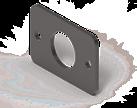
RECEPTACLES - FO1
PANEL FRONT MOUNTED
R13 - SQUARE FLANGE 1) BODY STYLE


1) Due to panel mounting with screws, sealing can’t be guaranteed at panel level.
Note: indicated connector P/N = delivered without contact, termini and rear accessory
dimensions and images shown are in millimeters and are for reference only.
R13LGR1 00A00 A 000 FO1 - R13 Receptacle FO1 R13 WIRE SET L20 D3.5 FO1 - R13 Receptacle wire set
PANEL CUT-OUT
RECEPTACLES - FO2/FO4
PANEL FRONT MOUNTED
R13 - SQUARE FLANGE 1)
BODY STYLE

REAR ACCESSORIES


FO2 R13LGR1 00A00 A 000 FO2 - R13 Receptacle
FO4 R13LGR1 00A00 A 000 FO4 - R13 Receptacle
FO2 R03-R13 WIRE SET L20 D6.5 FO2 - R03-R13 Receptacle wire set
FO4 R03-R13 WIRE SET L20 D6.5 FO4 - R03-R13 Receptacle wire set
FO2-4 R03-R13 CABLE CLAMP SET L49 D6 2)
FO2-4 R03-R13 POTTING SET L54 D10.8 2)
FO2/FO4 - R03-R13 Receptacle cable clamp set

PANEL CUT-OUT
FO2/FO4 - R03-R13 Receptacle potting set 73.7 with potting
1) Due to panel mounting with screws, sealing can’t be guaranteed at panel level.
2) The last number indicates the max compatible cable diameter in mm.
Note: indicated connector P/N = delivered without contacts, termini and rear accessory
RECEPTACLES - FOH
PANEL FRONT MOUNTED
R13 - SQUARE FLANGE 1) BODY STYLE

REAR ACCESSORIES
FOH R13LGR1 00A00 A 000 FOH - R13 Receptacle FOH R03-R13 WIRE SET L26 D8 FOH - R03-R13 Receptacle wire set
FOH R03-R13 POTTING SET L54 D10.8 2) FOH - R03-R13 Receptacle potting set
PANEL CUT-OUT

WIRE SET POTTING SET

Panel cut-out 24
1) Due to panel mounting with screws, sealing can’t be guaranteed at panel level.
2) The last number indicates the max compatible cable diameter in mm.
Note: indicated connector P/N = delivered without contacts, termini and rear accessory
dimensions and images shown are in millimeters and are for reference only.
OPTICAL TERMINI AND ELECTRICAL CONTACTS

Singlemode terminus
TERMINI SMA PC
Multimode terminus
TERMINI MMA PC Electrical contact (FOH Only)
Termini EL M ø1.25 SR A
CONNECTORS
■
■
■
■
■
Plugs
■ P01 = Cable mounted
Receptacles
■ R01 = Panel rear mounted, circular flange
■ R03 = Panel front mounted, circular flange
■ R13 = Panel front mounted, rectangular flange
■ R50 = Cable mounted
■ A = Delivered without rear accessory
■ W = Delivered with wire set accessory
■ C = Delivered with cable clamp set accessory
■ P = Delivered with potting set accessory
of electrical contacts (FOH only)
■ 00 = Delivered without electrical
■ 01 = Delivered with one electrical contact
■ 02 = Delivered with two electrical contacts
■ 03 = Delivered with three electrical contacts
■ 04 = Delivered with four electrical contacts
■ A = Delivered without optical terminus
■ S = Single-mode optical terminus
■ M = Multi-mode optical terminus
■ 00 = Delivered without optical terminus
■ 01 = Delivered with one optical terminus
■ 02 = Delivered with two optical termini
■
■ 03 = Delivered with three optical termini
= Delivered with four optical termini
CABLED PRODUCTS
Supply source
■ A = OCC
■ B = DRAKA
■ C = LEONI
■ D = BRUGG
Application environment
■ E = KAIPHONE
■ Z = Customer project
■
■
Plugs
■ P01 = Cable mounted plug
Receptacles
■ R01 = Panel rear mounted, circular flange
■ R03 = Panel front mounted, circular flange
■ R13 = Panel front mounted, rectangular flange
■ R50 = Cable mounted
■
Other connectors 1)
■ CNA = Free-end
■ CLC = LC
■ CSC = SC
■ CFC = FC
■ CST = ST
■ A = Indoor / outdoor
■ B = Outdoor rodent
Packaging
■ A = Cardboard box
■ B = Bag
■ C = Outdoor armored
■ Z = Specific / custom
■ R = Reel
A = Up to 20 meters length (10 meters for rodent and armored cables). From 20.1 meters length(10 meters for rodent and armored cables), select B.
B = Available from 20.1 to 49.9 meters. From 50 meters length, select R. R = from 50 meters length, cable assemblies are delivered on a reel.
Contact polishing
Single-mode
■ 0° = PC
■ 8° = APC
Multi-mode
■ 0° = PC
No connector on end B
■ Z = Not applicable
■ N = None (not cable potting nor clamping)
■ S9 = Single-mode 9/125
■ M5 = Multi-mode 50/125
■ M6 = Multi-mode 62.5/125
for breakout & sealed (if applicable / min. 0.3, max. 1.0)
1) Only for reel packaging option (R).
■ C = Cable clamp ■ P = Potting
Plugs
■ P01 = Cable mounted plug
Receptacles
■ R01 = Panel rear mounted, circular flange
■ R03 = Panel front mounted, circular flange
■ R13 = Panel front mounted, rectangular flange
■ R50 = Cable mounted
SOFT CAPS
FOR PLUGS FOR RECEPTACLES


FOCR14P 1B2 E150
R50 FOCR14C 1B2 A150
FOHCR14C 1B2 A150
DAISY CHAINING

LOOPBACK

Deployment accessories
PRE-CONFIGURED FIBEROPTIC REELS
2
1
9 (G657.A1)
1
2
4 FO4 P01P0 M5-050.0-00.0 P01P0
4
1

1
2 FO2 P01P0
COLOR CODING SILICONE RING SLEEVES HOLDER MATE ADAPTER OPEN SPANNER


HEXAGON SPANNER


FIBER OPTIC CLEANING KIT


LC Adapter SM/APC
Adapter SM/UPC
Adapter MM/UPC


Adapter SM/APC
Adapter SM/UPC


Clamp Black
GT380.RMFK
GT450.RMFK HT582.RM FC Adapter SM/APC
Adapter SM-MM
Adapter MM/UPC * Pre-configured reels can be found on page I-27. Reel selection can vary following cable choice and length.
SM-MM
Beige Blue
FOP06 Sleeve Holder
Jaws
FOP14 Sleeve Holder
MATERIAL & SURFACE FINISH
Metal components
Housing, nut
Back nut (plug)
FO1
Back nut (plug)
FO2, FO4, FOH
Brass CuZn39Pb3
Brass CuZn39Pb3
Brass CuZn39Pb3
Electrical contact Brass CuZn39Pb3
CW614N Chrome over Nickel SAE - AMS 2460 UNS C 38500
CW614N
Black Chrome over Nickel SAE - AMS 2460 UNS C 38500
CW614N
SAE-AMS-QQ-N-290 UNS C 38500
Nickel
CW614N UNS C 38500 1 µm Gold over Nickel
Shell contact Stainless steel X5CrNiMo18-10 (1.4401) -
Spring Stainless steel X10CrNi18-8 (1.4310) -
Mantel clip Stainless steel X5CrNiMo18-10 (1.4401) - -
Sleeve holder (plug) FO1 Brass CuZn39Pb3
Sleeve holder (center pin) FO2, FO4, FOH
SAE-AMS 2404
MIL-DTL-45204D Type 1 + ASTM B488 / SAE- AMSQQ- N- 290 / SAE- AMS 2404
Non-metallic components Material Flammability
Ferrules & sleeves Zirconia -
Contact housing
Contact block & sleeve holder
Mantel ring PTFE
O-rings FPM (Viton®)NBR (Nitrile) -
Sealant material Epoxy compoundCable strain relief
CW614N Nickel
SAE-AMS-QQ-N-290 UNS C 38500
SAE-AMS 2404
Stainless steel X8CrNiS18-9 (1.4305) -
Locking balls Stainless steel X46Cr13 (1.4034) -
ENVIRONMENTAL & MECHANICAL DATA
Characteristic
Sealing mated
Sealing unmated
IP68; 2 m submersion for 24 hours 1)
IP67 1)
IEC 60529
IEC 60529
Operating temperature range -40 °C to +85 °C (cable dependent) IEC 61300-2-22
Vibration
Shock
Salt mist
Mating durability
Sinusoidal, 10 - 55 Hz, 3 axes, 0.75 mm amplitude (max 10 g)1) IEC 61300-2-1
100 g 1) IEC 61300-2-9
1000 hours, 5% salt solution, 35 °C 1) 2) IEC 61300-2-26
1000 mating cycles 1) 3)
1) Exceeds IEC 61753-1 Cat.E Extreme Environment. Fischer Connectors can offer FO cable assemblies that are sealed to IP68 deeper than 2 m on request.
2) Connector must be mated
3) Recommended cleaning every 50 cycles.
FIBER TYPE AND PIN LAYOUT
Contact type
Single-mode 9/125 UPC
Single-mode 9/125 APC
Fiber standards Plug pin layout
G.657.A1
Multi-mode 50/125 - OM3
Multi-mode 62.5/125 - OM1 / OM1+
OPTICAL DATA
Characteristic Performance Standard
Insertion loss SM and MM ≤0.20 dB mean
≤0.45 dB max for >97% of samples
≤0.2 dB change during and after testing
Return loss SM UPC ≥50 dB
SM APC ≥70 dB (mated) and ≥50 dB (unmated)
ELECTRICAL DATA - FOH 2-2
IEC 61300-3-34 Random mated
IEC 61300-3-3
IEC 61300-3-6 Random mated
Characteristic Performance Standard
Number of contacts 2 contacts, ground by shell -
Current 10 [A] 1)
IEC 60512-5-2-5b
Rated voltage 400 [V] r.m.s. 2) EIA-364-20-B
Contact resistance (power contact) < 10 mΩ IEC 60512-2-1, Test 2a
Contact resistance (ground contact) < 50 mΩ IEC 60512-2-1, Test 2a
Insulation resistance > 1010 Ω IEC 60512-3-1-3a Method C
Contact termination Solder -
Wire size AWG17 / 1 mm 2 -
Test voltage AC 1.5 [kV] r.m.s
IEC 60512-4-1 Test 4a
Test voltage DC 2.8 [kV] IEC 60512-4-1 Test 4a
Receptacle pin layout
1) Current per contact at 40°C temperature rise measured on the basic curve according to IEC 60512-5-2-5b. Please refer to section A-12 to determine the maximum operating current.
2) Recommended operating voltage at sea leavel measured according to IEC 60664-1. Please refer to A-11
CONFIGURE YOUR SOLUTION
Quantity - Please use one request form per cable assembly type
Sealed receptacle Breakout
Drawings are for reference only. Available for FO1, FO2, FO4 and FOH 2-2
FiberOptic connectors
R50 - Receptacle cable mounted
R01 - Receptacle panel rear mounted P01 - Plug
R03 - Receptacle panel front mounted
R13 - Receptacle panel square flange
CNA - Free end No Connector 2)
Contact End-face Available for SM only
Total length Ltot 1) end-to-end total (min. 0.5 except receptacles)
FiberOptic connectors
R01 - Receptacle panel rear mounted P01 - Plug
Breakout length Lb 1) for breakout & sealed (if applicable / min. 0.3, max. 1.0)
Short length receptacles For receptacles < 0.5 meters 900 µm buffered fibers wires For receptacles > 0.5 meters 2.0 mm tight buffered wires 0.5 meter 1 meter 1 meter 2 meters
1) Cable length in 0.1 meter units only. Cable length tolerance according IPC-WHMA-A-620.
2) Only for reel packaging option (R).
R50 - Receptacle cable mounted Telecom connector
R03 - Receptacle panel front mounted
R13 - Receptacle panel square flange
CNA - Free end No Connector
Contact
CHOOSE YOUR CABLE
See our Cable Specifications for detailed information. Available Available under special lead time - please contact your local sales departement for details.
for
- Overall ruggedness
- Easy deployment - High end tactical cable - High load resistance - Easy deployment - High end tactical cable - Semi-static applications
- Easy deployment - Dielectric rodent protection - High flexibility
High rodent protection
Static & deployable applications - Ultra-light armored technology - Sensing applications - High rodent protection
- Static & deployable applications
- Self supporting applications
- Ultra-light armored technology
- Direct burial
Technology - Tight buffered fibers - Aramid yarn - PUR jacket - Tight buffered fibers - Aramid yarn - PUR jacket - Tight buffered fibers - Aramid yarn / - PUR double skin jacket - Stainless steel loose tube - Aramid yarn - LDPE jacket - Stainless steel loose tube - Stainless steel yarn - PA Jacket