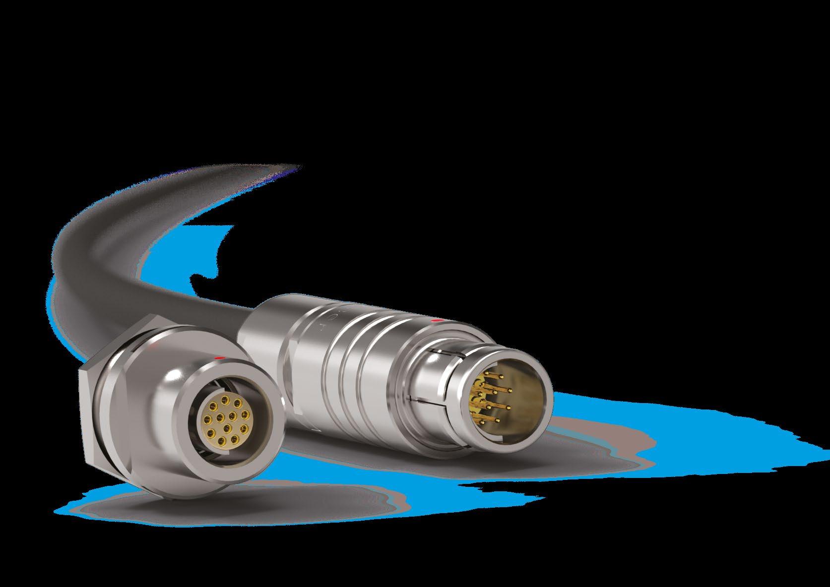
Fischer Connectors Core Series Stainless Steel Technical Catalogue
B7- 2 / B7- 30
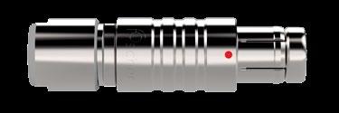
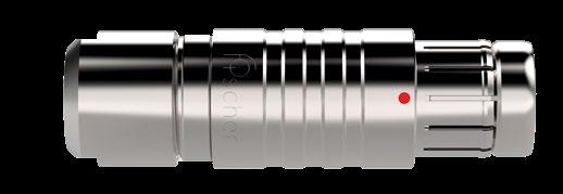
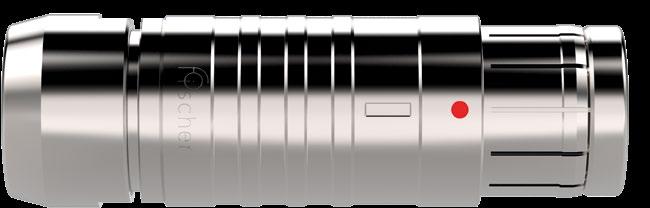
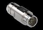
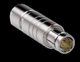
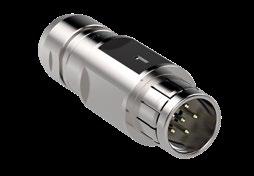
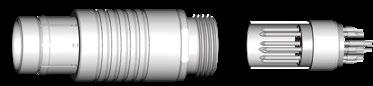
PLUGS
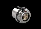
RECEPTACLES
PANEL REAR MOUNTED
FEEDTHROUGH
FOR ALL STAINLESS STEEL
AVAILABLE SIZES
CONNECTOR SIZE VERSUS CABLE DIAMETER
dimensions and images shown are in millimeters and are for reference only.
PLUGS
Body style
Protection
Unsealed (IP50)
Sealed up to IP68
Locking system Friction
Push-pull
Quick-release
Lanyard
Tamperproof
Contacts Crimp
Housing
Design
References to detailed information
Sealing categories, section A-6
Locking systems, page A-5
Electrical & configurations, page B 7-10 Solder
Standard
Remote handling
Shortened body
Straight Right-angle
Cable clamp sets
Cabling
Overmoldable
Heat shrinkable
Options, page B 7-17
Body styles, chapter B7-4
Cable clamp sets, page B 7-20
Accessories Cable bend reliefs
Size
Protective sleeves
Sealing caps
103 Series
Accessories, pages B6-10 and B7-24
Technical dimensions, page B 7-5
For more information visit our website www.fischerconnectors.com/technical 105 Series 107 Series
Technical dimensions
PLUGS
Torque [Nm] are recommended values that may be influenced by the characteristics of the cable jacket. Tests must be conducted to evaluate the exact values. To secure the cable clamp nut, we recommend the use of thread locking adhesive.
CABLE MOUNTED
All dimensions and images shown are in millimeters and are for reference only.
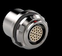
RECEPTACLES
Body
Protection
Contacts
Housing
Unsealed (IP50)
Sealed up to IP68
References to detailed information
Sealing categories, page A-6
Design
RECEPTACLES
PANEL FRONT MOUNTED
dimensions and images shown are in millimeters and are for reference only.
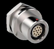
PANEL REAR MOUNTED
PANEL CUT-OUT
PANEL CUT-OUT
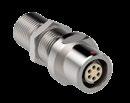
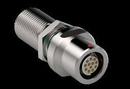
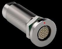
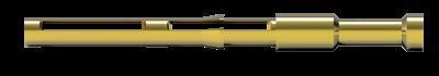
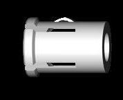
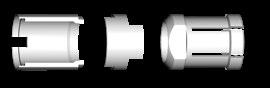
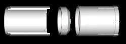
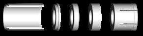
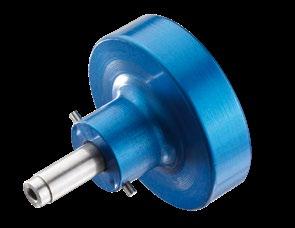
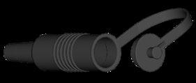
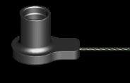
FEEDTHROUGH
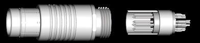
The bulkhead feedthrough connector allows the passing of electrical signals and power through a panel via two cable plugs.
The "AZ" version of the feedthrough accepts a type "A" plug on the flange side and a type "Z" plug on the threaded end, which is typically oriented toward the interior of the chassis. In the version "ZA" the connections "A" and "Z" are inverted.
Dimension "B max" specifies the maximum panel thickness. For panels thinner than the unthreaded section "E min", we can provide spacers as shown accessories section, page B 6-16.
1) Assembly tool for side hex nut, see Accessories section, page B 7-25.
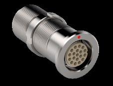
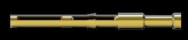
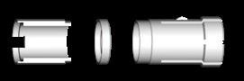
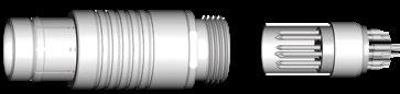
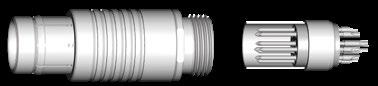
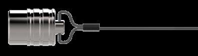
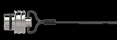
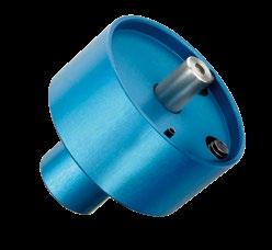
FEEDTHROUGH
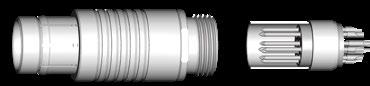
The bulkhead feedthrough connector allows the passing of electrical signals and power through a panel via two cable plugs.
The "AZ" version of the feedthrough accepts a type "A" plug on the flange side and a type "Z" plug on the threaded end, which is typically oriented toward the interior of the chassis. In the version "ZA" the connections "A" and "Z" are inverted.
Dimension "B max" specifies the maximum panel thickness. For panels thinner than the unthreaded section "E min", we can provide spacers as shown in accessories section, page B 6-16.
1) Assembly tool for side slotted nut, see Accessories section, page B 7-25.
Torque [Nm] are recommended values that may be influenced by the quality of the panel surface. Tests must be conducted to evaluate the exact values.
All dimensions and images shown are in millimeters and are for reference only.
A/Z POLARITY
To protect users from contact with dangerous voltages, most of our connectors exist in two versions:
STANDARD "A" POLARITY
The contacts of the receptacle are protected against accidental touch.
Recommended when voltage is present on the receptacle.
INVERTED "Z" POLARITY
The contacts of the plug are protected against accidental touch.
Recommended when voltage is present on the plug.
Standard Polarity
Type "Z"
Inverted Polarity
IMPORTANT : AN "A" TYPE CONNECTOR CAN NEVER BE MATED WITH A "Z" TYPE CONNECTOR.
A plug "ST-S" has the same housing in type "A" as in type "Z", but type "A" comes with unprotected contacts while type "Z" is equipped with
touch-protected contacts. In most cases these are female contacts which are recessed in the insulator.
BULKHEAD FEEDTHROUGH WDE
Type "AZ" is the standard version of the STWDE. The flange side accepts an "A" type plug, and the threaded side accepts a "Z" type plug.
The "ZA" version of the ST-WDE accepts a type "Z" plug at the flange side and accepts a type "A" plug at the threaded end.
Receptacle ST-DBEE Plug ST-S/ST-ST
Type "A"
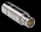
CONTACT TYPES
The Fischer Connectors’ contact designs are highly reliable and are guaranteed up to 5,000 mating cycles.
All standard brass and bronze contacts for use in the Core Series are screw machined, and all are gold plated over a nickel underplate.
Most connectors are available with solder, crimp or PCB contacts and each type is optimized for a particular application.
SOLDER CONTACTS
Most versatile
Pre-installed contacts
Qualified assemblers required
■ Can be produced with any type of contact block material and accept a wide range of wire sizes.
■ Contacts are pre-installed in the insulator block, and the wires can be terminated with any appropriately sized soldering iron.
■ May require operators who are qualified in specialized soldering techniques.
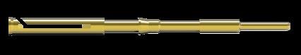
PCB CONTACTS
PCB or Flex circuit mount
Reduced pin diameter
Wave soldering
■ Designed to be mounted directly onto a PCB or flex circuit, can be used in wave soldering operations for faster production assembly.
■ Preferred for high rates of data transmission due to the low distance to the board that their integration allows. This helps reducing signal perturbations.
■ PCB pins are generally used on rear mounted panel connectors.
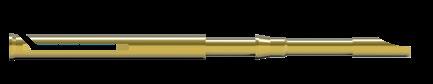
CRIMP CONTACTS
Selectively annealed area
Special tools required
Limited range of wire sizes
■ Each contact has a selectively annealed area which is deformed during assembly by specialized tooling to assure proper termination of the wire to the contact.
■ Commonly used for field termination or repair, as no soldering process is required.
■ Not available for sealed or hermetic connectors.
CONTACT TYPES
CRIMP CONTACTS
■ Selectively annealed area
■ Special tools required
■ Limited range of wire sizes
TOOLING FOR CRIMP CONTACTS
■ Each contact has a selectively annealed area which is crushed during assembly by specialized tooling to ensure proper termination of the wire to the contact.
■ Commonly used for field termination or repair, as no soldering is required.
■ Not available for sealed or hermetic connectors.
See following pages for description of crimp tool and positioner. Please refer to www.fischerconnectors.com/technical for detailed information and assembly instructions.
103 SERIES
103
103
1) Stranding values are in brackets.
2) For a given AWG, the diameter of some stranded conductor designs could exceptionally be larger than the hole diameter of the barrel. Testing may be required.
3) Current per contact at 40°C temperature rise measured on the basic curve according to IEC 60512-5-2-5b. For the max. operating current a reduction factor must be used and limitations due to the size of the wires and the permissible upper temperature limit of the materials employed must be taken into account. See page A-12 for details.
4) Recommended operating voltage at sea level measured according to IEC 60664-1.
5) Measured with ST-S plug and ST-D receptacle. Please contact us for rating for ST-WSO right-angle plugs and ST-WDE bulkhead feedthroughs.
105 SERIES
1) Stranding values are in brackets.
2) For a given AWG, the diameter of some stranded conductor designs could exceptionally be larger than the hole diameter of the barrel. Testing may be required.
3) Current per contact at 40°C temperature rise measured on the basic curve according to IEC 60512-5-2-5b. For the max. operating current a reduction factor must be used and limitations due to the size of the wires and the permissible upper temperature limit of the materials employed must be taken into account. See page A-12 for details.
4) Recommended operating voltage at sea level measured according to IEC 60664-1.
5) Contact dia. 2.0 is positioned to make contact first and break last.
6) Measured with S plug and D receptacle.
Electrical & contact configurations
105 SERIES
1) Stranding values are in brackets.
2) For a given AWG, the diameter of some stranded conductor designs could exceptionally be larger than the hole diameter of the barrel. Testing may be required.
3) Current per contact at 40°C temperature rise measured on the basic curve according to IEC 60512-5-2-5b. For the max. operating current a reduction factor must be used and limitations due to the size of the wires and the permissible upper temperature limit of the materials employed must be taken into account. See page A-12 for details.
4) Recommended operating voltage at sea level measured according to IEC 60664-1.
5) Contacts dia. 1.3 are positioned to make contact first and break last.
6) Contacts dia. 1.6 are positioned to make contact first and break last.
7) Inverted polarity: female contacts on plug/male contact on receptacle
8) Measured with S plug and D receptacle.
Electrical & contact configurations
107 SERIES
AWG21 [1] AWG22 [7/30]
AWG20 [1] AWG22 [19/34]
1) Stranding values are in brackets.
2) For a given AWG, the diameter of some stranded conductor designs could exceptionally be larger than the hole diameter of the barrel. Testing may be required.
3) Current per contact at 40°C temperature rise measured on the basic curve according to IEC 60512-5-2-5b. For the max. operating current a reduction factor must be used and limitations
the size of the wires and the permissible upper temperature limit of the materials employed must be taken into account. See page A-12 for details.
4) Recommended operating voltage at sea level measured according to IEC 60664-1.
5) Measured with S plug and D receptacle.
MECHANICAL CODING
For easy connect/disconnect operations
Our contact blocks are engineered with arc-shape metal guides, which ensure precise alignment of connectors during the mating process.
This guiding mechanism provides:
■ Increased safety and user friendliness by preventing misconnection.
■ Easy mating cycles, can be blind-mated.
Keying codes option
All Multipole body styles are mechanically coded. Code 1 is the standard, but other codes can be requested.
Code 1
Receptacle
Other keying codes are available on request, please contact us.
Images are for reference only.
MULTIPOLE LOW VOLTAGE OPTIONS
OPTIONS
1 Housing color Which housing color do you need ? Natural Stainless steel
2 Contact block material Which contact block material do you need ? PEEK
3 Contact type Which contact type do you need ? Solder Crimp1)
4 Keying code Which keying code do you need ? Code 1 -130 -150
1) Crimp contacts are not an option for sealed or hermetic connectors.
CONTACT TYPE FOR PANEL MOUNTED CONNECTORS
Applicable for Last digit Description
0 Standard : solder contacts
Front mounted : ST-DBEE
All dimensions and images shown are in millimeters and are for reference only.
Rear mounted : ST-DBPE
9 With PCB (Printed Circuit Board) contacts instead of solder contacts
0 Standard : PCB (Printed Circuit Board) contacts
9 With solder contacts instead of PCB (Printed Circuit Board) contacts
Options are available on request, please contact us.
ORDERING INFORMATION
How to build a part number
Refer to the table aside to find the information you need to build the part number to order your selected connector.
For customized solutions, please contact us.
CONNECTORS PARTS
ST- S cable mounted plug in Series 103 with 6 (multipole) low voltage male contacts and following options.
ST- DBEE panel mounted receptacle in Series 103 with 6 (multipole) low voltage female contacts and following options.
Cable mounted plugs Series As standard rule
A = male contacts on plug and female contacts on receptacle
Panel mounted receptacles
ST-DBEE
ST-DBPE
ST-WDE
See page B 7-3 or Technical dimensions B 7-5
Z = female contacts on plug and male contacts on receptacle
See page B 7-10
ORDERING INFORMATION
056 -130 +
Stainless steel housing, PEEK contact blocks with solder contacts, keying code 1 and clamp nut without bend relief.
056 -130E Not applicable as panel mounted
Stainless steel housing, PEEK contact blocks with solder contacts and keying code 1.
Ex: ST-CR105C 2C3 A150 Ex: TX00.240
Stainless steel cap Crimping tool
Three-digit number specific for each pin layout
Specific suffix corresponding to selected options
Below cable clamp sets should be ordered separately
Housing color Multipole low voltage
Protective sleeves
Soft caps
Metal caps
Spacers
Washers
Mounting nuts Spanners / Wrenches Crimping tools
Tools for crimp contacts and high voltage contacts
PEEK See page B 7-20
Contact type
Solder Crimp PCB
Keying code of the contact block
Clamp nut type & color
Other options
See page B 7-17
CABLE CLAMP SETS
To guarantee excellent cable retention and strain relief, Fischer Connectors provides robust and high quality cable clamp sets :
■ Collet style clamp system retaining cable over large jacket surface area.
■ Protection of small diameters and delicate conductors.
Cable clamp sets are suitable for all cable mounted connectors.
RANGE OVERVIEW : S, U & E CABLE CLAMP SETS
Fischer Connectors offers three types of cable clamps sets. The table below will help you select the one corresponding to your needs.
PART NUMBERING
Cable clamp sets below should be ordered separately
Multipole low voltage
Cable clamp set
Do you need the interface between the cable and the connector to be sealed ?
Do you need the connector to be terminated to the cable shield ?
For 107 Series connectors, only S and E cable clamp sets are available.
ST- S 103 A056-130+
Examples connector ordering line
ST- S103 A056-130+
Clamp set ordering line
E3 102.5/2.0
See following pages for cable clamp sets selection.
Cable clamp sets
103 SERIES
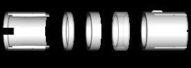
S SHIELDED
Shielded cable clamp with spacer and sleeve.
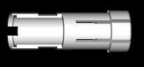
UNSHIELDED
Unshielded, one-piece cable clamp.
E
ENVIRONMENTAL
Environmentally sealed clamp for use with shielded or unshielded cables.
dimensions and images shown are in millimeters and are for reference only.
105 SERIES
S SHIELDED
Shielded cable clamp with spacer and sleeve.
UNSHIELDED
Unshielded, one-piece cable clamp.
E
ENVIRONMENTAL
Environmentally sealed clamp for use with shielded or unshielded cables.
Clamp Sleeve
Spacer Clamp
107 SERIES
S SHIELDED
E ENVIRONMENTAL
dimensions and images shown are in millimeters and are for reference only.
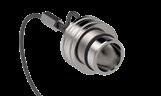
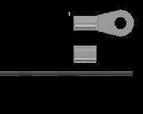
STAINLESS STEEL CAPS
FOR RECEPTACLES FOR PLUGS
They protect and seal the mating face of the plugs and receptacles. To attach the ferrule or the crimp lug to the stainless steel cable, use a crimp tool, a vice or a pair of pliers with parallel jaws. Other available accessories listed on page B7-30. Cable strain relief, Protective Boots, sealing caps )Plasticx, Soft caps).
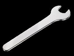
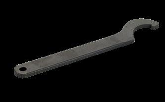
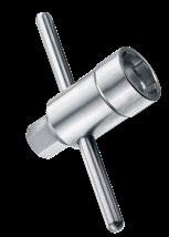
SPANNERS & NUTDRIVER
DOUBLE-END OPEN SPANNER EXTRA THIN
OPEN-END SPANNER EXTRA THIN
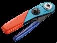
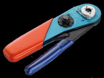
CRIMPING TOOLS
CRIMP TOOL ULTRA PRECISION
FOR CLOSED CRIMP TERMINATION
- 000 or
TX00.242 1.6 ASTRO TOOL 615708
The best choice of precision crimp tools for highly reliable eight indenter crimping per US-MIL, IEC and DIN Specifications. Positioners have to be ordered according to contact.
Standards
IEC 60203 / DIN 41 611, Part 3 / MIL- C-22520, Class I, Type 1
POSITIONER
SUITABLE FOR CRIMP TOOL TX00.240
SUITABLE FOR CRIMP TOOL TX00.242
For the choice of Fischer Connectors’ positioner, please refer to section "Tooling", page B 2-26.
FOR CRIMP CONTACTS
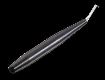
CONTACT INSERTION TOOL
Part
TX00.214 0.5
TX00.210
Material
Handle: black POM (Delrin®)
Fork: tool steel, chrome plated
Tool for inserting male and female removable crimp contacts into the contact block. Especially recommended for small gauge and fragile wires.
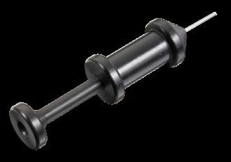
CONTACT EXTRACTION TOOL
TX00.213
TX00.200
Material
Housing and plunger: black POM (Delrin®)
Sleeve: stainless steel
Slide: tool steel
Tool for extracting male and female removable crimp contacts from the contact block. The sleeve of this tool is pushed over the contact, to release the contact retaining mechanism. The tool plunger is then pushed to eject the contact.
dimensions and images shown are in millimeters and are for reference only.
Cable clamp, inner sleeve, spacers and rings, nuts and washers
Brass CuZn39Pb3 CW614N / UNS C 38500 Nickel SAE-AMS-QQ-N-290 / SAE-AMS2404
Contacts Male (solder) Brass CuZn39Pb3 CW614N / UNS C 38500 1 µm Gold over Nickel MIL-DTL-45204D / Type 1 + ASTM B488 Female, Male (crimp) Bronze CuSn4Zn4Pb4 CW456K / ASTM B 139 / UNS C 54400
Other material and surface treatments are available on request.
Insulator and sealing
Contact blocks and other insulators for our standard connectors are manufactured from high performance engineering plastic materials. The standard materials for each connector series are listed under Electrical & contact configurations in pages B 7-13 through B 7-16. Ceramics and other dielectrics are available on special order.
Insulator and sealing International symbol Flammability
Insulator PEEK UL 94 V-O
Panel and contact block O-rings (receptacles) FPM (Viton ®) -
1) The sealing performance can be affected by the long term quality of the cable.
2) For information only. Not tested by Fischer Connectors.
Most of our connectors are completely sterilizable in autoclave, Cidex® , EtO, gamma radiation, Steris® or Sterrad®. Please contact us for more details. For more information visit: www.fischerconnectors.com
ELECTRICAL DATA
Characteristic
Contact resistance 5,000 mating cycles
IEC 60512-2-1, Test 2a IEC 60512-2-2, Test 2b
Insulation resistance > 1010Ω IEC 60512-3-1-3a Method C
All dimensions and images shown are in millimeters and are for reference only.
IEC 60068-2-11 test Ka
MIL-STD-202 method 101 condition A
IEC 60512-9-1 / EIA-364-09
MIL-STD-202 method 204 condition B
OPERATING TEMPERATURES
The temperature ranges quoted by the manufacturers of the plastic materials are usually the absolute maximum values. When exposed to the mechanical and electrical stresses present in a connector, these values are often unachieveable.
If a composite connector system including accessories is used, then the item with the lowest temperature performance will dictate the operating temperature limit of the system. The table below shows our recommended operating temperature ranges.