CHAPTER


EASY MATING | EASY CLEANING | EASY INTEGRATION
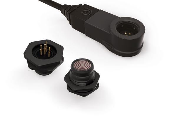
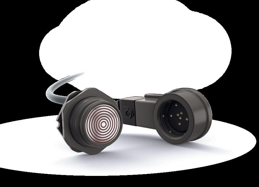
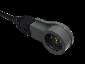
■ No key code: 360° mating freedom & optimized cable management
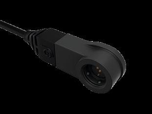
■ Non-magnetic locking mechanism
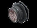
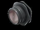
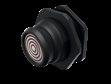
■ Membrane-sealed contacts (patent pending)
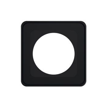
■ Low profile
■ IP68 sealed to 20 m/24 h
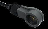
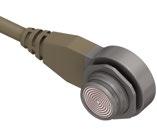
■ No key code = 360° mating freedom
■ Optimized cable management – no more tangles and turns, cables always go in a straight line
■ Non-magnetic quick-release locking mechanism
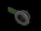
■ Surface contacts = fixed tracks & membranesealed contacts
■ 2x less protruding compared to a normal pin-socket type of connector
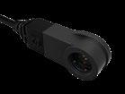
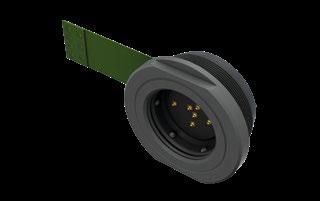
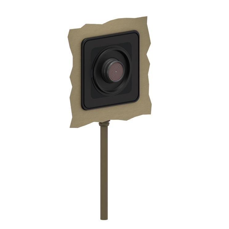
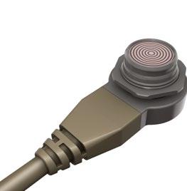
A true low-profile solution
Ideal for integration in wearable applications or on panels where space and access are limited LP360TM CONNECTOR
CONNECTOR
to IP67
Protection
Sealed up to IP68
Locking system
Termination
Housing
Note: Plug is only available pre-cabled with a standard length (1 m). For customized solutions, please contact sales.
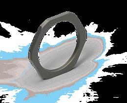
NUT ACCESSORY
Nut to be ordered separately. Available in different sizes.
Body style
Protection
Sealed to IP67
Sealed up to IP68
Hermetic
Termination Wires
PCB contacts
Stainless steel
Housing material
Housing color
Aluminum
Plastic
Anthracite
Black
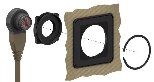
Design Front projecting
Assembly Front mounting
Rear mounting
Cable bend relief
Protective sleeves
Accessories
Sealing caps
References to detailed information
Sealing categories, pages K-17 & 18
Electrical & contact configurations, page K -11
Page K -12
Page K -12
Body styles, pages K-8 to 10
Page K -15
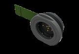
Garment fixation Page K -16
Size 08
Technical dimensions, pages K-8 to 10 14
All dimensions are in millimeters and images are for reference only.
NUT ACCESSORY
Nut to be ordered separately. Metal nut available in different sizes. Refer to Accessories section for garment fixation.
Nut to be ordered separately. Refer to Accessories section for garment fixation. NUT ACCESSORY
All dimensions are in millimeters and images are for reference only.
Note: Receptacle is only available pre-cabled with a standard length (1.0 m). For customized solutions please contact sales.
Nut to be ordered separately. Available in different sizes. Refer to Accessories section for garment fixation. NUT ACCESSORY
1) Current per contact at 40 °C temperature rise measured on the basic curve according to IEC 60512-5-2-5b. For the max. operating current, a reduction factor must be used and limitations due to the size of the wires and the permissible upper temperature limit of the materials employed must be taken into account.
2) Recommended operating voltage at sea level. This rated voltage is a general-purpose guideline where no other electrical safety standard applies. In case where other standards rule a specific use of the connector, then the application-specific safety criteria shall be considered first. This must be evaluated in the frame of equipment engineering.
3) Based on IEC 61984 safety requirements, Fischer Connectors recommends that, for operating voltage >50 V, power should not be used without integration of an active security system. Please contact us for further information.
4) N/A for plastic version.
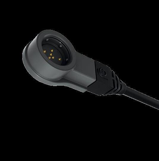
View from the front of the receptacle (grounding pin at 12 o’clock)
Body style
■ F = Freedom
■ L = Low profile
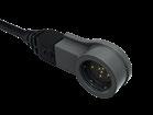
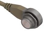
■ P01 = Cable plug right angle
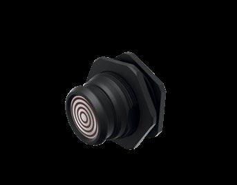
■ P03 = Panel plug
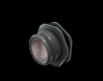
■ R01 = Rear mounted receptacle
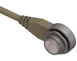
■ R50 = Cable mounted receptacle
Sealing level
Plug
■ Z = Not applicable
Receptacle
■ W = Water sealing
Locking system
Plug
■ QM = Quick-release medium force
Receptacle
■ ZZ = No locking
Connector size
■ 08 = Size 08 (interface diameter)
■ 14 = Size 14 (interface diameter)
Polarity of contacts
■ P = Piston
■ T = Track
Number of contacts
■ Size 08 = 004
■ Size 14 = 007 Contact type
■ A = Flex print Solder
■ B = Flex print ZIF 1)
■ S = Solder
■ P = PCB
Housing material
■ B = Brass (plug)
■ C = Stainless steel (receptacle)
■ D = Plastic
Grounding
■ A = Grounding pin (receptacle)
■ Z = Not applicable (plug)
Insulating material
■ 2 = Plastic (plug)
■ 3 = Epoxy (receptacle)
O-ring material
Plug = Interface O-ring
Receptacle = Panel O-ring
■ V = Viton®
■ Z = Not applicable
Keying code
■ 360 = No code
Housing color
■ AN = Anthracite
■ BK = Black
■ PUR halogen free, flame retardant outer sheath, black (RAL9005 matt) / Tan (RAL 7002 matt)
■ Working voltage: ≤ 100 V
■ Weight: 34 kg/km
■ Overall
■ Breaking strength: ≤ 100 N
■ Recommended bending radius: 20 mm static / 40 mm dynamic
■ Working temperature: -30 °C to +80 °C
■ Weight: 29 kg/km
■
Pre-cabled plug / receptacle configurations
■ PUR halogen free, flame retardant outer sheath, nominal thickness 0.55 mm, black (RAL9005 matt / TAN (RAL 7002 matt)
■ Working voltage: 100 V
■ Weight: 45 kg/km
■ Breaking strength: 400 N (Vectran central strength member)
■ Recommended bending radius: 40 mm static / 60 mm dynamic
■ Working temperature: -40 °C to +90 °C
■ Overall diameter: nominal 5.35 mm / maximal 5.50 mm
AWG28 (white/green twisted)
Tinned copper conductor 7x0.13 mm / polypropylene insulation / nominal thickness 0.28 mm / nominal diameter 0.95 mm / characteristic impedance 90 ±10 Ω Tinned copper drain wire 7x0.13 mm, aluminum / polyester tape
AWG26 (black/red)
Tinned copper conductor 7x0.16 mm / polypropylene insulation / nominal thickness 0.21 mm / nominal diameter 0.90 mm
AWG24 (blue/brown/orange)
Bare copper conductor 7x0.20 mm / polypropylene insulation / nominal thickness 0.20 mm / nominal diameter 1.0 mm
Shield
Tinned copper braid / coverage 95% / wire diameter 0.13 mm
Wiring diagram front view:


Characteristic Performance Standard
Sealing Connectors in mated condition or with cap
Plug without cap
Receptacle without cap
Operating temperature range (connectors only) -55 °C to +135 °C
Corrosion resistance mated
Salt mist 1,000 h 1) Connectors in mated condition.
IP68, 20 m / 24 h
IP67, 0.2 m / 30 min
IP68, 20 m / 24 h
Cosmetic changes may appear over time without impacting mechanical or electrical functions.
Mechanical endurance 10,000 mating cycles / 5,000 full rotations 2) Preserved mechanical and electrical functionality. Normal wear will appear.
Random vibration 9.26 G rms
Unmating force Typical 40 N
Shock 30 G
1) Exception for FLR50: 200 h mated and unmated.
2) 180° rotation considered per mating within the mating cycle test.
Characteristic Performance Standard
Contact resistance
<50 mOhm (typical value) MIL- STD- 202 Method 307
Shell resistance <50 mOhm (cabled; new condition) MIL- STD- 202 Method 307
Insulation resistance >1010 Ohm MIL- STD- 202 Method 302, IEC 60512-3-1
Shielding effectiveness 360° shielded -
Data protocols USB 2.0 and 100 Mbit/s Ethernet
IEC 60512- 9- 1
STD- 202 Method 214 Condition I
IEC 60512- 13- 1

Characteristic Performance
Sealing Connectors in mated condition or with cap Plug without cap Receptacle without cap
Operating temperature range (connectors only)
IP67, 0.2 m / 30 min
IP67, 0.2 m / 30 min
IP67, 0.2 m / 30 min
°C to +85 °C
Corrosion resistance mated Salt mist 1,000 h Connectors in mated condition. Cosmetic changes may appear over time without impacting mechanical or electrical functions.
Mechanical endurance 5,000 cycles / 2,500 full rotations
Random vibration 9.26 G rms
Unmating force Typical 24 N
Shock 30 G
1) 180° rotation considered per mating within the mating cycle test.
Characteristic Performance Standard
Contact resistance <50 mOhm (typical value) MIL- STD- 202 Method 307
Insulation resistance >1010 Ohm IEC 60512-3-1 MIL-STD-202 Method 302
Shielding effectiveness N/A N/A
Data protocols USB 2.0 and 100 Mbit/s Ethernet
IEC 60512- 9- 1
MIL-STD-202G Method 214A Condition I
IEC-60512-13-1
EIA-364-27B MIL-STD-202G Method 213B Condition J, K