
SIMPLIFICATION IS OUR INNOVATON Visit www.radiall.com for more information SECTION 18 COAXIAL CABLE ASSEMBLIES C291
the right cable for your application ...................................................................................................................
Finder guide cables vs insertion loss ...............................................................................................................
FLEXIBLE CABLES (STANDARD)
0.8/50 S cable (132390 type)
1/50 S cable (50VMTX type)
1/75 S cable (75VMTX type)
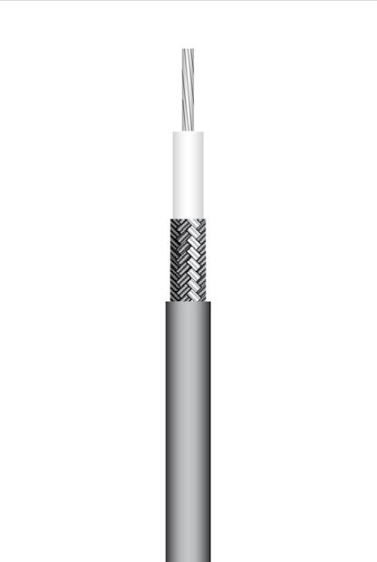
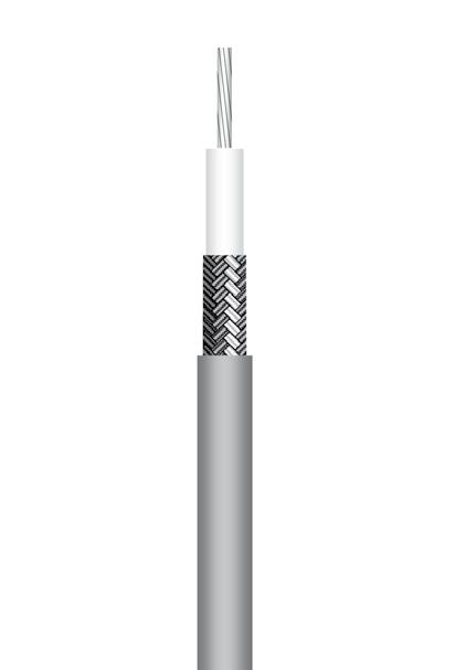
2/50 S cable (RG178-KX21A-RG178 non mag)
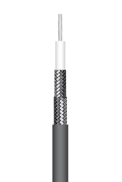
2/50 D cable (124416 type)
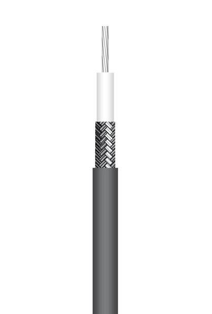
2/75 S cable (296775 type)
2.6/50 S cable (RG174-KX3B-RG316-KX22A) 18-11 to 18-12
2.6/50 D cable (RD316) 18-12
2.6/75 S cable (RG179)
4.6/75 D cable (HD 0.6/2.8-mini RG59 type) 18-13
5/50 S cable (RG58-KX15)
5/50 D cable (RG142-RG223-RG400-KX23)
6/75 S cable (RG59-KX6A)
6/75 D cable (HD 0.8/3.7-RG59 type) 18-17
7/75 D cable (HD 1.0/4.8-RG6 type) 18-18 10/50 S cable (RG213-KX4) 18-18
10/50 D cable (RG393)
D cable (RG214-KX13) .........................................................................................................................................
D
FLEXIBLE CABLES (LOW-LOSS ECO-FRIENDLY)
2.6/50 S cable (ECO316-ECO316X) 18-20 to 18-21
2.6/50 D cable (ECO316D-ECO316DX) 18-21 to 18-22
5/50 D cable (ECO142-ECO142X-Power142) 18-22 to 18-23
6/50 D cable (ECO230) 18-24
10/50 D cable (ECO393-ECO393X) 18-24 to 18-25
CORRUGATED CABLES
Cable 1/4" spiral (HCF 1/4"-50 AlCu) 18-25
Cable 3/8" spiral (HCF 3/8" CuH-50 AlCu)
Cable 1/2" spiral (HCF 1/2" CuH-50 AlCu) 18-26
SEMI-RIGID AND HAND-FORMABLE CABLES
.047" cable (SR copper-SR tinned copper) 18-27 .085" cable (Handformable unjacketed-SR RG405/KS1-SR tinned copper-SR non magnetic-SR aluminum) 18-28 to 18-30 .141" cable (Handformable unjacketed-Handformable FEP jacketed-SR RG402/KS2 SR tinned copper-SR silvered copper-SR non magnetic-SR aluminum) .................................... 18-30 to 18-33 .250" cable (SR RG401/KS3-SR aluminum) 18-34
LOW-LOSS FLEXIBLE CABLES AEP-100FR (LMR® 100)
AEP-195FR (LMR® 195)
AEP-200FR (LMR® 200)
AEP-240FR (LMR® 240) 18-38
AEP-400FR (LMR® 400) 18-39
AEP-600FR (LMR® 600) 18-40
SHF ULTRA LOW LOSS CABLES 18-41 to 18-44
Radiall cable groups
Example for flexible cables: 5/50 S
Example for corrugated cables: 1/2 spiral
Example for semi-rigid & handformable cables: .141"
Cable outer diameter in mm (2.6 mm, 5 mm, 10 mm, 11 mm,…)
Characteristic impedance (50Ω, 75Ω)
Number of shields (S=single, D=double)
Cable outer conductor diameter in fraction of inch (1/4", 3/8", 1/2",…)
Cable outer conductor diameter in inches (.085", .141", .250",…)
18-3 Go online for data sheets & assembly instructions. Visit www.radiall.com and enter the part number. SIMPLIFICATION IS OUR INNOVATION
Introduction 18-4
18-5
18-6
18-7
CABLE ASSEMBLIES
Specify
to
18-8
18-8
18-9
18-9
to 18-10
18-10
18-11
18-13
18-14
18-14 to 18-16
18-16
18-17
to
18-19 11/50
18-19 11/75
cable (RG216) ................................................................................................................................................... 18-20
18-26
18-36
18-35
18-37
Contents SECTION 18 TABLE OF CONTENTS
CABLE ASSEMBLIES
Introduction
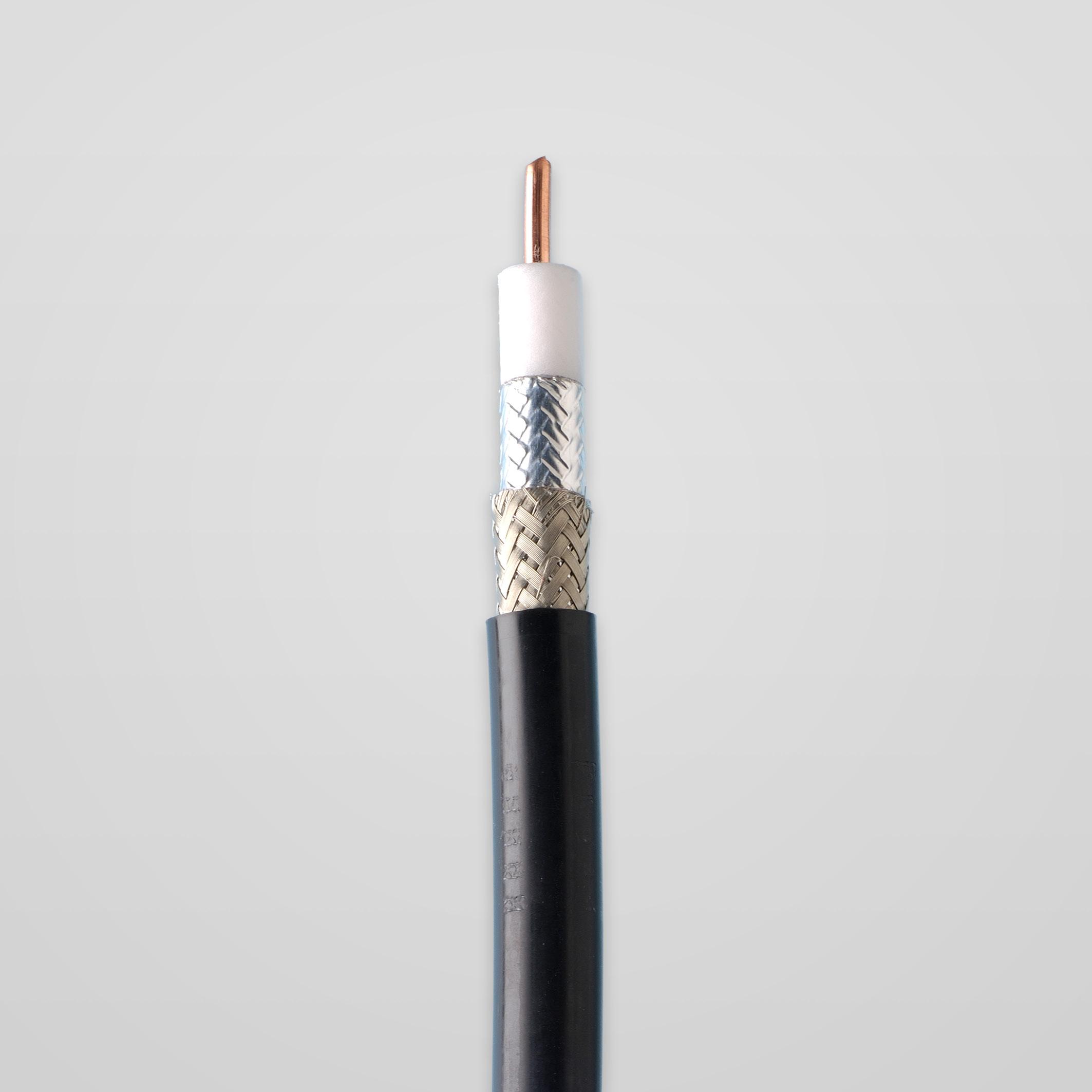
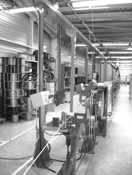
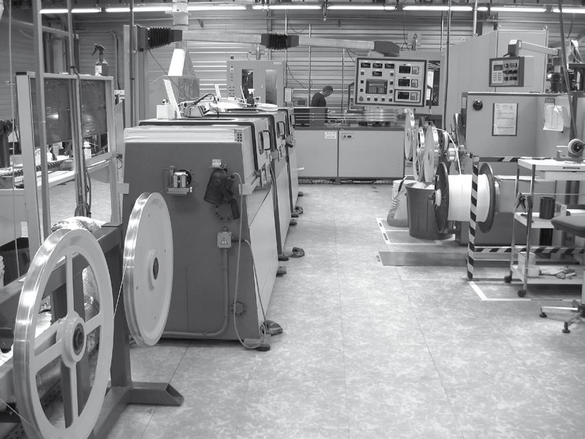
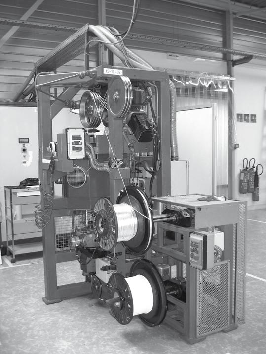
Radiall is globally recognized as a leading manufacturer of coaxial connectors, cable and cable assemblies.
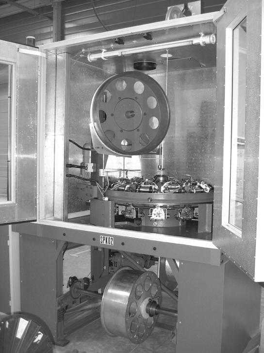
Radiall has top tier manufacturing technology and processes. As a result, we are one of the only manufacturers that have fully mastered foam PTFE wrapping technology. This capability enables us to supply cable assemblies featuring the highest level of performance, stability and repeatability.
In addition, Radiall has high precision stripping and cutting machines, soldering and cleaning equipment.
Radiall offers five standard ranges of cable for a wide variety of applications for the telecom, military, instrumentation, medical and broadcast markets.
Requirements for Designing a Custom Cable Assembly
Start with identifying the needed components and the required information for your cable assembly:
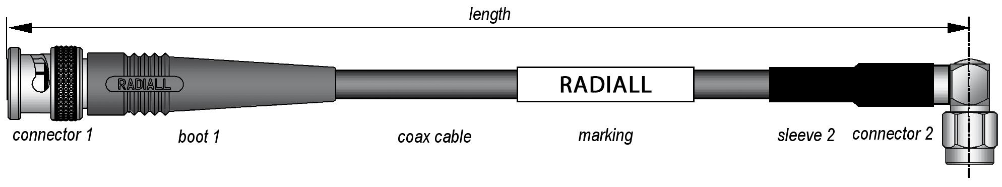
- Coaxial cable (p/n or description)
- Connector 1 (p/n or description)
- Optional boot 1 or heat-shrink sleeve 1 (p/n or description)
- Connector 2 (p/n or description)
- Pptional boot or sleeve 2 (p/n or description)
- Length: radiall standard = overall length (or please specify if length between reference planes) + Length tolerance (radiall standard = ±2%)
- Marking: Radiall standard = RADIALL + p/n + batch code (or please specify if different)
- Connectors orientation (if needed for right-angle or panel connectors)
For you will also need the following dimensions and information:
- Stripping A dimension
- Stripping B dimension
- Stripping C dimension
- Tinned inner conductor (if needed)
- Tinned braid (if needed)
18-4 Go online for data sheets & assembly instructions. Visit www.radiall.com and enter the part number. SIMPLIFICATION IS OUR INNOVATION
Specify the Right Cable for Your Application
Flexible cables (Standard)
Standardized by MIL-C-17 US government specification since the 40’s, these familiar P/N’s are mainly used for military RF and microwave applications.
Every electrical, mechanical and environmental performance is controlled and in compliance with the relevant standard.
KX cables are equivalent to RG cables under French standards (NF). These cables perfectly suited for dynamic applications (bending moment) or those requiring flexibility for ease of connection.
Flexible cables (low-loss Eco-friendly)
These high performance custom cables have been designed for optimized electrical and environmental requirements.
Cost effective compared with RG cables, they are the perfect alternative to fulfill your needs.
These cables are halogen free and flame retardant to meet safety environmental regulations.
Hand-formable cables
Using a tin-dipped braid technology, these cables are a compromise between performance and flexibility.
They allow easy routing during installation (without spring-back effect) and multiple repositions on site.
Preserving high performance level (low loss and high shielding efficiency,) they are a good cost-effective alternative to semirigid cables.
Corrugated cables
The outer conductor of these cables is constituted of a corrugated tube (spiral or ringed winding).
This construction allows perfect shielding and some bendability while respecting large bending radius.
The high performance level of these cables enable them to be used in outdoor long length transmission lines.
Semi-rigid cables
The solid tubing technology allows definitive and high precision forming. These cables use only high grade insulation material and feature optimal shielding effectiveness. They provide the highest electrical performance (e.g: the lowest insertion loss).
KS cables are equivalent to semi-rigid RG cables under French standards (NF).
These cables can also be used for cosmetic appeal where straight and clear cable path must be demonstrated.
CABLE ASSEMBLIES
18-5 Go online for data sheets & assembly instructions. Visit www.radiall.com and enter the part number. SIMPLIFICATION IS OUR INNOVATION
flexibility attenuation
FLEXIBLE CABLES (STANDARD)
Cable group Cable p/n
0.8/50 S C291 042 066 132390 type
1/50 S C291 050 066 50 VMTX type
1/75 S C291 055 076 75 VMTX type
2/50 S C291 145 007/017
RG178/KX21
C291 140 087 RG178 non mag type
2/50 D C291 146 087 124416 type
2/75 S C291 147 060 296775 type
2.6/50 S C291 150 000/010 RG174/KX3B
C291 170 007/017
RG316/KX22A
2.6/50 D C291 185 067 RD316
2.6/75 S C291 210 007 RG179
5/50 S C291 305 000/010 RG58/KX15
C291 320 007 RG142
C291 330 000 RG223
5/50 D
C291 324 007 RG400
C291 322 017 KX23
C291 325 270 POWER142 0.41/0.12
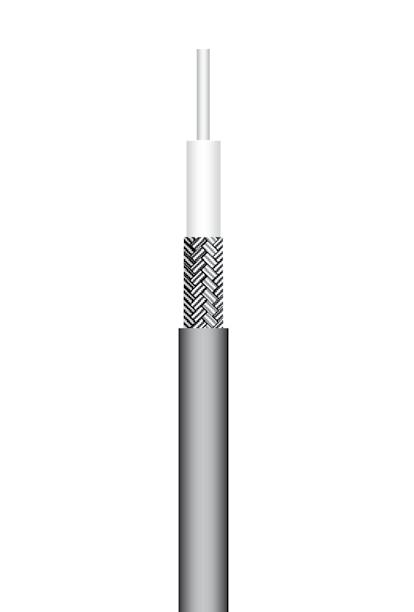
6/75 S C291 360 000 RG59 0.44/0.13 -
C291 351 012 KX6A 0.48/0.15
10/50 S C291 510 000/010 RG213/KX4
10/50 D C291 511 007 RG393
11/50 D C291 600 000/010 RG214/KX13
11/75 D C291 610 000 RG216
(11) = 11 GHz
FLEXIBLE CABLES (LOW-LOSS ECO-FRIENDLY)
(alternative to RG cables - in accordance with RoHS regulation)
2.6/50 S C291 999 904 ECO316
-
C291 171 083 ECO316X
2.6/50 D
999 905 ECO316D
217 020 ECO316DX
5/50 D C291 325 290 ECO142 0.41/0.12 0.58/0.18 0.72/0.22C291 320 180 ECO142X
6/50 D C291 326 490 ECO230 0.28/0.08 0.40/0.12
10/50 D C291 491 060 ECO393 0.16/0.05
C291 512 020 ECO393X 0.29/0.09
-
(4) = 4 GHz
LOW-LOSS FLEXIBLE CABLES (AEP-xxxFR cables)
Cable
C291 327 060 LMR®
AEP-600FR C291 327 050 LMR®
18-6 Go online for data sheets & assembly instructions. Visit www.radiall.com and enter the part number. SIMPLIFICATION IS OUR INNOVATION
Cable type 1 GHz (VHF/UHF) dB/m dB/ft 2 GHz (band L) dB/m dB/ft 3 GHz (band S) dB/m dB/ft 6 GHz (band C) dB/m dB/ft 8 GHz (band C) dB/m dB/ft 12.4 GHz (band X) dB/m dB/ft
2.41/0.73 3.51/1.06 4.93/1.49
- -
-
2.12/0.64 3.36/1.02 4.45/1.35
- -
-
2.22/0.67
- - - -
3.14/0.95
1.54/0.47 2.20/0.67 2.72/0.82 - - -
1.34/0.41 1.92/0.58 2.37/0.72 - - -
1.92/0.58
1.34/0.41
2.37/0.72 - - -
1.38/0.42 1.98/0.60 2.46/0.75 - - -
- - -
1.07/0.32 - -
0.86/0.26 1.24/0.38 1.54/0.47 - - -
0.86/0.26 1.24/0.38 1.54/0.47 - - -
- -
0.95/0.29 1.37/0.41 1.70/0.51 -
0.67/0.20 - - - - -
0.44/0.13 0.65/0.20 0.81/0.25 1.22/0.37 1.45/0.44 1.90/0.58
0.46/0.14 0.67/0.20 0.85/0.26 1.27/0.38 1.51/0.46
1.97/0.60
0.52/0.16 0.76/0.23 0.95/0.29 1.42/0.43 1.68/0.51 2.19/0.66
0.48/0.14 0.70/0.21 0.89/0.27 1.35/0.41
- - -
1.61/0.49
0.58/0.18 0.72/0.22
- - - -
- - - -
-
- - - -
0.23/0.07 0.35/0.11 0.45/0.14 0.71/0.21 0.86/0.26
0.24/0.07 -
1.07(11)/0.32(11)
0.24/0.07 0.36/0.11 0.47/0.14 0.73/0.22 0.89/0.27
1.1(11)/0.33(11)
0.32/0.10 0.48/0.14 0.60/0.18
- -
Cable group Cable p/n Cable type 1 GHz (VHF/UHF) dB/m dB/ft 2 GHz (band L) dB/m dB/ft 3 GHz (band S) dB/m dB/ft 6 GHz (band C) dB/m dB/ft
0.76/0.23 1.09/0.33 1.34/0.41
0.96/0.29 1.45/0.44 1.85/0.56
0.76/0.23 1.09/0.33 1.34/0.41
1.30/0.40 1.68/0.51
C291
C291
0.86/0.26
2.64/0.80
0.54/0.16 0.83/0.25 1.07/0.32
1.70/0.51
0.50/0.15
0.59/0.18(4)
0.47/0.14 0.64/0.19 1.11/0.34
0.24/0.07 0.30/0.09
type 1 GHz (VHF/UHF) dB/m dB/ft 2 GHz (band L) dB/m dB/ft 3 GHz (band S) dB/m dB/ft 6 GHz (band C) dB/m dB/ft AEP-100FR
100 0.79/0.24 1.16/0.35 1.45/0.44 2.15/0.65 AEP-195FR
327
LMR® 195 0.39/0.12 0.55/0.17 0.69/0.21 1.00/0.3 AEP-200FR
200 0.34/0.10 0.49/0.15 0.61/0.19 0.88/0.27
240 0.26/0.08 0.38/0.11 0.47/0.14 0.68/0.21
400 0.14/0.04 0.20/0.06 0.24/0.07 0.36/0.11
0.13/0.04
group Cable p/n Cable
C291
010
C291 327 020 LMR®
AEP-240FR C291 327 030 LMR®
AEP-400FR C291 327 040 LMR®
600 0.09/0.03
0.16/0.05 0.24/0.07 Finder Guide - Cables vs Insertion Loss
CABLE ASSEMBLIES
Finder Guide - Cables vs Insertion Loss
STANDARD FLEXIBLE HD CABLES
Cable group Cable p/n
4.6/75 D C291 333 039
6/75 D C291 360 093
7/75 D C291 384 083
0.8/3.7 RG59 type
CORRUGATED CABLES (spiral outer shielding)
Celiflex 1/4" C291 993 170 HCF 1/4"-50 AlCu
Celiflex 3/8" C291 996 170 HCF 3/8" CuH-50 AlCu
Celiflex 1/2" C291 994 170 HCF 1/2" CuH-50 AlCu
-(11.7) = 11.7 GHz (10) = 10 GHz
HAND-FORMABLE AND SEMI-RIGID CABLES
Cable group
C291 844 065 Handformable unjacketed
C291 850 001 SR RG405/KS1
C291 864 065 Handformable unjacketed
18-7 Go online for data sheets & assembly instructions. Visit www.radiall.com and enter the part number. SIMPLIFICATION IS OUR INNOVATION
Cable type 1 GHz (VHF/UHF) dB/m dB/ft 2 GHz (band L) dB/m dB/ft 3 GHz (band S) dB/m dB/ft 4.5 GHz (band C) dB/m dB/ft
0.34/0.10 0.50/0.15 0.62/0.19 -
HD 0.6/2.8 mini RG59 type
0.25/0.07 0.35/0.11 0.44/0.13 0.54/0.16
HD
HD
0.19/0.06 0.28/0.08 0.35/0.11 0.44/0.13
1.0/4.8 RG6 type
Cable
p/n Cable type 2 GHz (band L) dB/m dB/ft 3 GHz (band S) dB/m dB/ft 6 GHz (band C) dB/m dB/ft 8 GHz (band C) dB/m dB/ft 12.4 GHz (band X) dB/m dB/ft 18 GHz (band Ku) dB/m dB/ft 20 GHz (band Ku) dB/m dB/ft
group Cable
0.27/0.08 0.34/0.10 0.51/0.15 0.60/0.18 0.78/0.24 0.99/0.30
0.19/0.06 0.24/0.07 0.36/0.11 0.43/0.13 0.54(11.7)/
1.06/0.32
0.16(11.7) - -
0.16/0.05 0.20/0.06 0.30/0.09 0.36/0.11 0.42(10)/ 0.13(11.7)
Cable p/n Cable type 2 GHz (band L) dB/m dB/ft 3 GHz (band S) dB/m dB/ft 6 GHz (band C) dB/m dB/ft 8 GHz (band C) dB/m dB/ft 12.4 GHz (band X) dB/m dB/ft 18 GHz (band Ku) dB/m dB/ft 20 GHz (band Ku) dB/m dB/ft
855 001 SR copper 1.64/0.50 2.03/0.61 2.93/0.89 3.43/1.04 4.73/1.32 5.39/1.63 5.72/1.73 C291 855 065 SR tinned copper 1.64/0.50 2.03/0.61 2.93/0.89 3.43/1.04 4.73/1.32 5.39/1.63 5.72/1.73
.047" C291
.085"
2.10/0.64 2.71/0.82 3.39/1.03 3.62/1.10
0.97/0.29 1.21/0.37 1.78/0.54
0.94/0.29
2.05/0.62 2.64/0.80 3.31/1.00 3.53/1.07
0.94/0.29 1.18/0.36 1.73/0.53 2.05/0.62 2.64/0.80 3.31/1.00 3.53/1.07 C291
SR non magnetic 0.94/0.29 1.18/0.36 1.73/0.53 2.05/0.62 2.64/0.80 3.31/1.00 3.53/1.07 C291 844 187 SR aluminum 0.98/0.30 1.22/0.37 1.80/0.54 2.12/0.64 2.73/0.83 3.41/1.03 3.64/1.10 .141"
1.18/0.36 1.73/0.53
C291 850 005 SR tinned copper
851 001
0.57/0.17 0.72/0.22 1.09/0.33 1.30/0.39 1.71/0.52 2.18/0.66 2.34/0.71
0.63/0.19 0.80/0.24 1.20/0.36 1.42/0.43 1.87/0.57 2.37/0.72 2.54/0.77
RG402/KS2 0.50/0.15 0.64/0.19 0.97/0.30 1.17/0.35 1.55/0.47 1.99/0.06 2.14/0.65 C291 862 005 SR tinned copper 0.50/0.15 0.64/0.19 0.97/0.30 1.17/0.35 1.55/0.47 1.99/0.06 2.14/0.65
861 066 SR silvered copper 0.50/0.15 0.64/0.19 0.97/0.30 1.17/0.35 1.55/0.47 1.99/0.06 2.14/0.65 C291 861 061 SR non magnetic 0.50/0.15 0.64/0.19 0.97/0.30 1.17/0.35 1.55/0.47 1.99/0.60 2.14/0.65 C291 864 187 SR aluminum 0.53/0.16 0.67/0.20 1.02/0.31 1.23/0.37 1.62/0.49 2.08/0.63 2.23/0.38 .250" C291 870 001 SR RG401/KS3 0.31/0.09 0.41/0.12 0.64/0.20 0.79/0.24 1.08/0.33 1.42/0.43 1.54/0.47 C291
187 SR aluminum 0.33/0.10 0.43/0.13 0.68/0.21 0.83/0.25 1.13/0.34 1.48/0.45 1.60/0.49
C291 866 378 Handformable FEP jacketed
C291 860 001 SR
C291
874
CABLE ASSEMBLIES
CABLE ASSEMBLIES
P/N: C291 042 066
APPLICATION NOTE
The very small outer diameter and bending moment of this cable allow very easy routing during installation.
Its very light weight makes it perfect to be used in all miniature and space saving applications.
The insulation and jacket materials allow this cable to be used in severe thermal conditions.
CONSTRUCTION / DIMENSIONS
P/N: C291 050 066
APPLICATION NOTE
The very small outer diameter and bending moment of this cable allow very easy routing during installation.
Its very light weight makes it perfect to be used in all miniature and space saving applications.
The insulation and jacket materials allow this cable to be used in severe thermal conditions.
CONSTRUCTION / DIMENSIONS
ELECTRICAL CHARACTERISTICS
MECHANICAL CHARACTERISTICS
ELECTRICAL CHARACTERISTICS
Characteristic impedance
MECHANICAL
ENVIRONMENTAL CHARACTERISTICS
ENVIRONMENTAL CHARACTERISTICS
Operating temperature range -90 / +200 °C -130 /
FREQUENCY / ATTENUATION (typ.) / CW MAX POWER (sea level / 40 °C)
SPC = Silver Plated Copper
PTFE = PolyTetraFluoroEthylene
FEP = Fluorinated Ethylene Propylene
Note:
18-8 Go online for data sheets & assembly instructions. Visit www.radiall.com and enter the part number. SIMPLIFICATION IS OUR INNOVATION
type)
vmtx type)
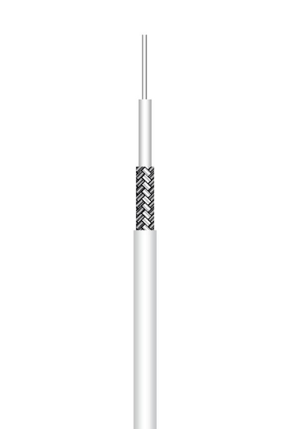
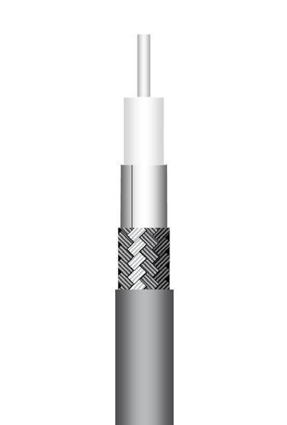
Flexible cable 0.8/50 S (132390
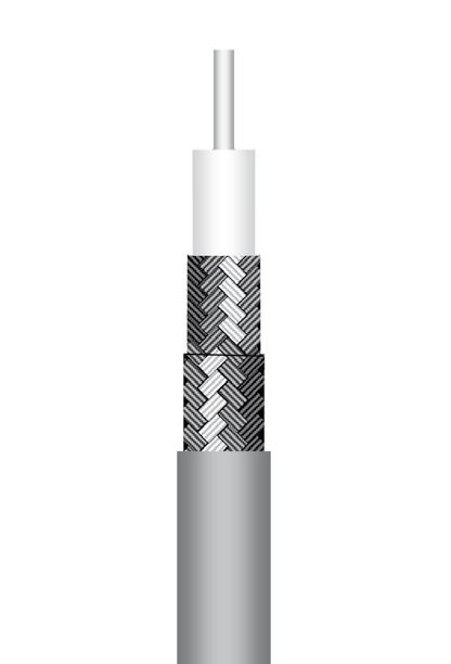
Flexible cable 1/50 S (50
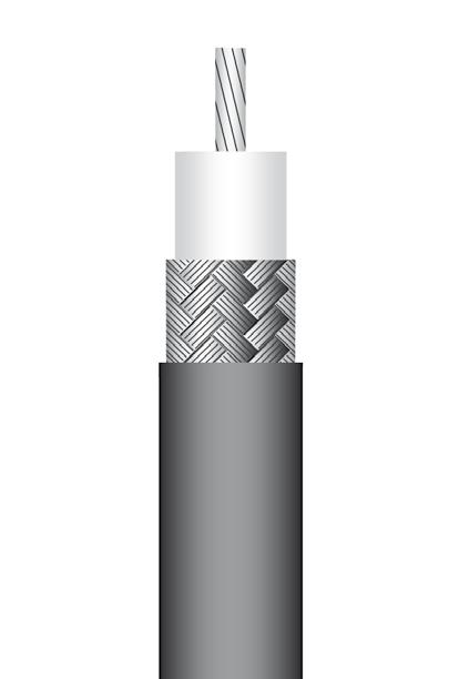
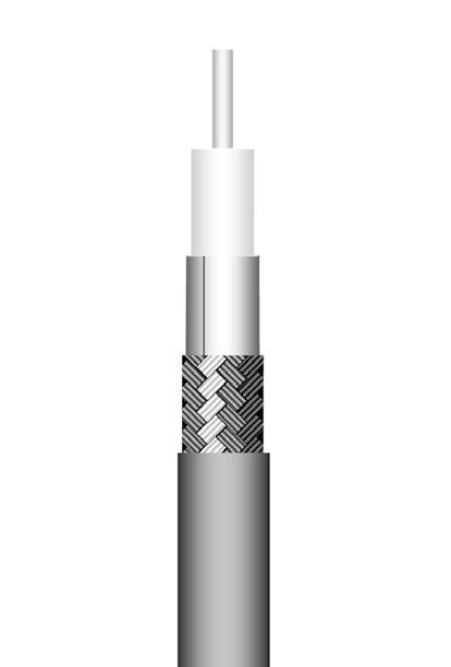
Material mm Inches Center conductor Solid SPC(1) 0.16 0.006 Dielectric Solid PFA(2) 0.50 0.020 Inner shield SPC(1) braid 0.70 0.028 Outer shield - -Jacket White FEP(3) 0.83 max 0.033 max
impedance 50Ω ± 3Ω Operating frequency range DC - 3 GHz Shielding effectiveness 40 dB Voltage withstanding 18 000 V rms Peak power 6 kW Capacitance 98.7 pF / m 29.9 pF / ft Velocity of propagation 69 % (4.8 ns / m)
Characteristic
Recommended minimum bending radius 4 mm 0.157 inch Weight 1.8 g / m 0.001 Ibs / ft
Operating temperature range -50 / +200 °C -58 / +392 °F Fire resistance Yes (UL94V0) Halogen free No FREQUENCY / ATTENUATION (typ.) / CW MAX POWER (sea level / 40 °C) GHz dB / m dB / ft Watts 0.1 0.64 0.19 45 0.2 0.88 0.27 34 0.3 1.90 0.58 28 0.4 1.28 0.39 22 0.5 1.48 0.45 20 1.0 2.41 0.73 14 1.5 3.03 0.92 12 2.0 3.51 1.06 10 2.5 4.20 1.27 9 3.0 4.93 1.49 8 (1) SPC = Silver Plated Copper (2) PFA = PerFluoroAlkoxy (3) FEP = Fluorinated Ethylene Propylene
Material mm Inches Solid SPC(1) 0.17 0.007 Dielectric Solid PTFE(2) 0.52 0.020 Inner shield SPC(1) braid 0.70 0.028 Outer shield - -Jacket White FEP(3) 1.17 0.046
50Ω ± 5Ω
DC - 3 GHz Shielding
40 dB Voltage
19 000 V rms Peak power 7 kW Capacitance 94 pF / m 28.5 pF / ft Velocity of propagation 69 % (4.8 ns / m)
Operating frequency range
effectiveness
withstanding
CHARACTERISTICS Recommended minimum bending radius 6 mm 0.236 inch Weight 3 g / m 0.002 Ibs / ft
+392 °F Fire resistance Yes (UL94V0)
Halogen free No
GHz dB / m dB / ft Watts 0.1 0.54 0.16 82 0.2 0.80 0.24 58 0.3 1.01 0.31 45 0.4 1.20 0.36 39 0.5 1.37 0.42 34 1.0 2.12 0.64 25 1.5 2.76 0.84 21 2.0 3.36 1.02 17 2.5 3.91 1.19 15 3.0 4.45 1.35 14 Attenuation
x √f GHz)
(0.61 x f GHz)
calculation (dB/m) (1.51
+
(1)
(2)
(3)
Typical attenuation for a couple of connectors (dB) = 0.045 x √f (GHz)
P/N:
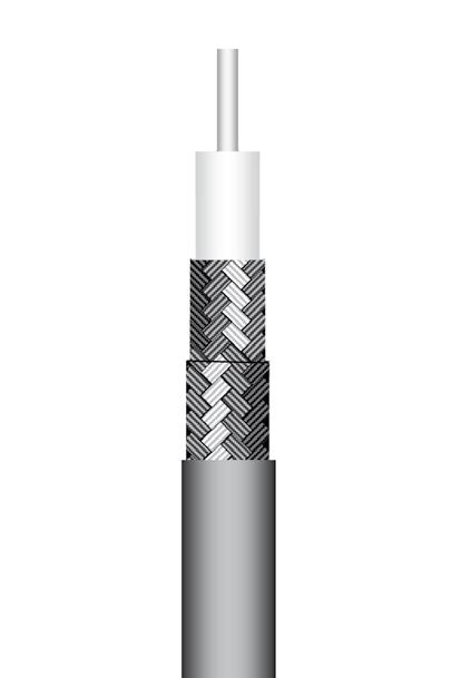
C291 055 076
Due to its 75 ohms characteristic impedance, this cable is best suited for TV/Video applications.
The very small outer diameter and bending moment allow very easy routing during installation. Its very light weight makes it perfect to be used in all miniature, space saving and dynamic applications. Suitable for severe thermal conditions.
CONSTRUCTION / DIMENSIONS
P/N: C291 145 007 (MIL-C-17/93-RG178)
P/N: C291 145 017 (NF-C-93/550-KX21A)
Due to its small diameter and its stranded inner conductor, RG 178 / KX21A is used for applications requiring high flexibility.
Its very low bending moment allows an easy routing during installation.
The insulation and jacket materials allow this cable to be used in severe thermal conditions.
CONSTRUCTION / DIMENSIONS
ELECTRICAL CHARACTERISTICS
Characteristic
MECHANICAL CHARACTERISTICS
ENVIRONMENTAL CHARACTERISTICS
Operating temperature range -90 / +200 °C -130 / +392 °F
Fire resistance Yes (UL94V0)
Halogen free No
FREQUENCY / ATTENUATION (typ.) / CW MAX POWER (sea level / 40 °C)
dB / m dB / ft Watts
Attenuation calculation (dB/m) (2.21 x √f GHz) + (0.005 x f
(1) SPCCS = Silver Plated Copper covered steel
(2) PTFE = PolyTetraFluoroEthylene
(3) SPC = Silver Plated Copper
(4) FEP = Fluorinated Ethylene Propylene
Note:
ELECTRICAL CHARACTERISTICS
Characteristic impedance 50Ω ± 3Ω
Operating frequency range DC - 3 GHz
Shielding effectiveness 40 dB
Voltage withstanding 2 000 V rms
Peak power
MECHANICAL CHARACTERISTICS Recommended
ENVIRONMENTAL CHARACTERISTICS
Operating
Halogen free No
FREQUENCY / ATTENUATION (typ.) / CW MAX POWER (sea level / 25 °C)
Attenuation calculation (dB/m) (1.50 x √f GHz) + (0.04 x f GHz)
Power calculation (W) 60 / √f GHz
(1) SPCCS = Silver Plated Copper covered steel
(2) PTFE = PolyTetraFluoroEthylene
(3) SPC = Silver Plated Copper
(4) FEP = Fluorinated Ethylene Propylene
18-9 Go online for data sheets & assembly instructions. Visit www.radiall.com and enter the part number. SIMPLIFICATION IS OUR INNOVATION APPLICATION NOTE APPLICATION NOTE
cable 1/75
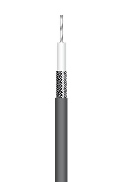
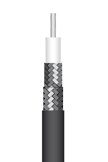
vmtx type) Flexible cable 2/50 S (RG178 - KX21A)
Flexible
S (75
Typical attenuation for a couple of connectors (dB) = 0.045 x √f (GHz)
Material mm Inches Solid SPCCS(1) 0.10 0.004 Dielectric Solid PTFE(2) 0.57 0.022 Inner shield SPC(3) braid 0.80 0.031 Outer shield - -Jacket White FEP(4) 1.22 0.048
impedance 80Ω
8Ω Operating frequency range DC
2 GHz Shielding effectiveness 40 dB Voltage withstanding 2 600 V rms Peak power 0.9 kW Capacitance 60 pF / m 18.3 pF / ft Velocity of propagation 69 % (4.8 ns / m)
±
-
Recommended minimum bending radius 6.1 mm 0.240 inch Weight 3 g / m 0.002 Ibs / ft
0.1 0.70 0.21 86 0.2 0.99 0.30 64 0.3 1.21 0.37 50 0.4 1.40 0.42 41 0.5 1.57 0.47 38 0.6 1.71 0.52 35 0.8 1.98 0.60 30 1.0 2.22 0.67 26 1.5 2.71 0.82 21 2.0 3.14
18
GHz
0.95
GHz)
Material mm Inches Center conductor Stranded SPCCS(1) 0.30 0.012 Dielectric Solid PTFE(2) 0.84 0.033 Inner shield SPC(3) braid 1.30 0.051 Outer shield - -Jacket Brown FEP(4) 1.78 0.07
1 kW Capacitance 96 pF / m 29 pF / ft Velocity of propagation 70 % (4.8 ns / m)
minimum bending radius 7 mm 0.275 inch Weight 8 g / m 0.0053 Ibs / ft
temperature
-55 / +200 °C -67 / +392 °F
(CSA FT6 / IEC 332-2)
range
Fire resistance Yes
GHz dB / m dB / ft Watts 0.1 0.48 0.14 190 0.2 0.68 0.21 134 0.3 0.83 0.25 110 0.5 1.08 0.33 85 1.0 1.54 0.47 60 1.5 1.90 0.57 49 2.0 2.20 0.67 42 2.5 2.47 0.75 38 3.0 2.72 0.82 35
CABLE ASSEMBLIES
CABLE ASSEMBLIES
P/N:
C291 140 087
(MIL-C-17/93-RG178)
APPLICATION NOTE
Based on MIL-C17/93 US standard, this cable is used where non magnetic is required.
In addition the solid inner conductor allows reduced attenuation in comparison with standard RG178.
The insulation and jacket materials allow this cable to be used in severe thermal conditions.
CONSTRUCTION / DIMENSIONS
P/N: C291 146 087
APPLICATION NOTE
Due to its small diameter this cable will be used for applications requiring flexibility. Its low bending moment allows an easy routing during installation.
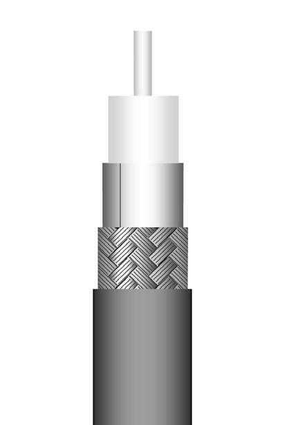
The double braid provides a higher level of shielding in comparison with 2mm single braided cables.
In addition the solid inner conductor provides a very good attenuation level.
The insulation and jacket materials allow this cable to be used in severe thermal conditions.
CONSTRUCTION / DIMENSIONS
ELECTRICAL CHARACTERISTICS
ELECTRICAL CHARACTERISTICS
Characteristic impedance
Operating frequency range DC - 3 GHz
Shielding effectiveness 80 dB Voltage withstanding 3 000 V rms
MECHANICAL CHARACTERISTICS
MECHANICAL CHARACTERISTICS
ENVIRONMENTAL CHARACTERISTICS
FREQUENCY / ATTENUATION (typ.) / CW
(sea level / 25 °C)
ENVIRONMENTAL CHARACTERISTICS
Operating
Fire resistance Yes (UL94V0)
Halogen free No
FREQUENCY / ATTENUATION (typ.) / CW MAX POWER (sea
calculation
Note:
18-10 Go online for data sheets & assembly instructions. Visit www.radiall.com and enter the part number. SIMPLIFICATION IS OUR INNOVATION
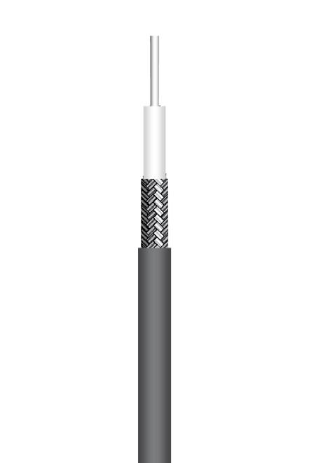
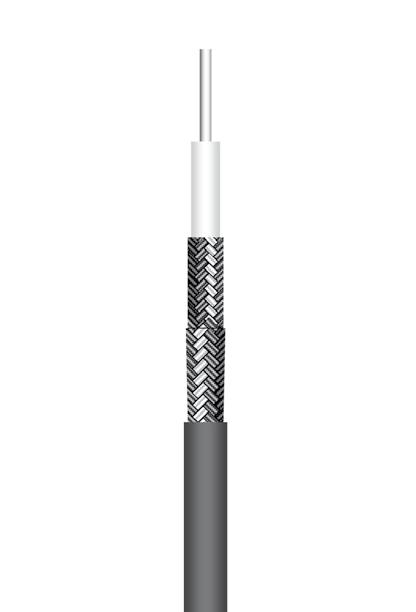
Flexible cable 2/50 S (non magnetic RG178 type) Flexible cable 2/50 D (124416 type)
Typical attenuation for a couple of connectors (dB) = 0.045 x √f (GHz)
Material mm Inches Center conductor Solid SPC(1) 0.29 0.0114 Dielectric Solid PTFE(2) 0.84 0.033 Inner shield SPC(1) braid 1.30 0.051 Outer shield - -Jacket Brown FEP(3) 1.80 0.071
impedance 50Ω ± 2Ω Operating frequency range DC - 3 GHz Shielding effectiveness 40 dB Voltage withstanding 2 000 V rms Peak power 1 kW Capacitance 100 pF / m 30 pF / ft Velocity of propagation 70 % (4.8 ns / m)
Characteristic
Recommended minimum bending radius 9 mm 0.354 inch Weight 8 g / m 0.0053 Ibs / ft
Operating temperature range -55 / +200 °C -67 / +392 °F Fire resistance Yes (CSA FT6 / IEC 332-2) Halogen free No
MAX POWER
GHz dB / m dB / ft Watts 0.1 0.42 0.13 253 0.2 0.59 0.18 179 0.3 0.72 0.22 146 0.5 0.94 0.28 113 1.0 1.34 0.41 80 1.5 1.65 0.50 65 2.0 1.92 0.58 57 2.5 2.16 0.65 51 3.0 2.37 0.72 46 Attenuation calculation (dB/m) (1.30 x √f GHz) + (0.04 x f GHz) Power calculation (W) 80 / √f GHz
Copper
(1) SPC = Silver Plated
(2) PTFE = PolyTetraFluoroEthylene (3) FEP = Fluorinated Ethylene Propylene
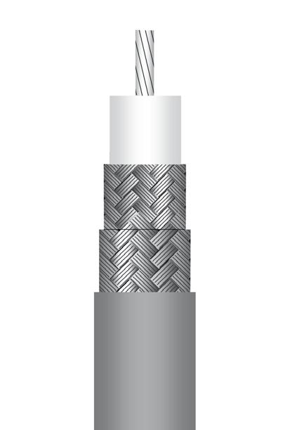
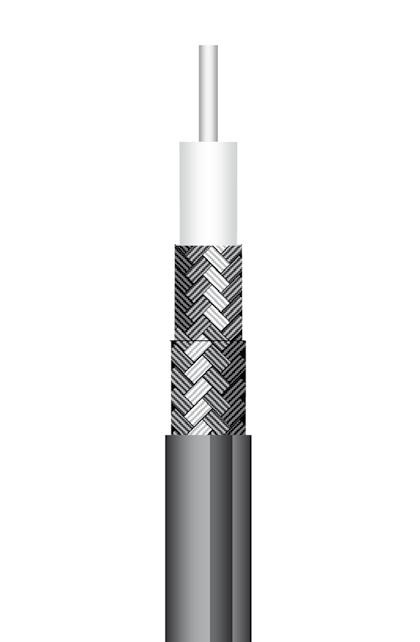
Material mm Inches Center conductor Solid SPC(1) 0.29 0.011 Dielectric Solid PTFE(2) 0.84 0.033 Inner shield SPC braid 1.27 0.050 Outer shield SPC braid 1.60 0.063 Jacket Brown FEP(3) 2.10 0.083
50Ω ± 2Ω
Peak
105 pF / m 32 pF / ft Velocity of propagation 69 % (4.8 ns / m)
power 1.8 kW Capacitance
Recommended minimum bending radius 12.5 mm 0.49 inch Weight 12.5 g / m 0.0083 Ibs / ft
+200 °C -130 / +392 °F
temperature range -90 /
level
°C) GHz dB / m dB / ft Watts 0.1 0.42 0.13 253 0.2 0.59 0.18 179 0.3 0.72 0.22 146 0.5 0.94 0.28 113 1.0 1.34 0.41 80 1.5 1.65 0.50 65 2.0 1.92 0.58 57 2.5 2.16 0.65 51 3.0 2.37 0.72 46
/ 40
GHz)
Attenuation
(dB/m) (1.30 x √f GHz) + (0.04 x f
Power calculation (W) 80 / √f GHz (1) SPC = Silver Plated Copper (2) PTFE = PolyTetraFluoroEthylene (3) FEP = Fluorinated Ethylene Propylene

P/N: C291 147 060
Due to its 75 ohms characteristic impedance, this cable is is best suited for TV/Video and networks applications. Its small diameter and light weight make it perfect to be used in all miniature, space saving and dymamic applications. APPLICATION NOTE
CONSTRUCTION / DIMENSIONS
P/N: C291 150 000 (MIL-C-17/119-RG174)
P/N: C291 150 010 (NF-C-93/550-KX3B) Cost effective solution
APPLICATION NOTE
For cost savings in low frequency applications, RG174 may be used instead of RG316 when environmental conditions like operating temperature allow it. This cable is compatible with a large range of connector series.
CONSTRUCTION / DIMENSIONS
ELECTRICAL CHARACTERISTICS
Characteristic
MECHANICAL CHARACTERISTICS
ELECTRICAL CHARACTERISTICS
Characteristic impedance
Operating frequency range
effectiveness
withstanding
MECHANICAL CHARACTERISTICS
Recommended
CHARACTERISTICS
resistance No
Halogen free Yes (IEC 754-2)
FREQUENCY / ATTENUATION (typ. / 25 °C) / CW MAX POWER (sea level / 40 °C)
ENVIRONMENTAL CHARACTERISTICS
Operating temperature range -40 / +85
FREQUENCY / ATTENUATION (typ.) /
Attenuation calculation (dB/m) (1.317 x √f GHz) + (0.06
(1) SPCCS = Silver Plated Copper covered steel
(2) PE = PolyEthylene
(3) SPC = Silver Plated Copper
(4) LSZH PE = Low Smoke Zero Halogen PolyEthylene
18-11 Go online for data sheets & assembly instructions. Visit www.radiall.com and enter the part number. SIMPLIFICATION IS OUR INNOVATION
Typical attenuation for
couple of connectors (dB) = 0.045 x √f (GHz) Flexible cable 2/75 S (296775 type) Flexible cable 2.6/50 S (RG174 - KX3B)
Note:
a
Material mm Inches Center conductor Solid SPCCS(1) 0.17 0.007 Dielectric Solid PE(2) 1.00 0.039 Inner shield SPC(3) braid 1.32 0.052 Outer shield - -Jacket Black LSZH PE(4) 1.90 0.075
impedance 75Ω
frequency range DC
effectiveness 50 dB min Voltage withstanding 8 000 V rms Peak power 400 W Capacitance 67 pF / m 20.1 pF / ft Velocity of propagation 66 % (5 ns / m)
± 5Ω Operating
- 3 GHz Shielding
Recommended minimum bending radius 10 mm 0.394 inch Weight 6.6 g / m 0.0044 lbs / ft
ENVIRONMENTAL
Operating temperature range -60 / +85 °C -40 / +185 °F Fire
GHz dB
m
ft Watts 0.1 0.42 0.13 41 0.2 0.60 0.18 29 0.3 0.74 0.22 23 0.4 0.86 0.26 20 0.6 1.06 0.32 16 1.0 1.38 0.42 12 1.5 1.70 0.52 10 2.0 1.98 0.60 8 2.5 2.23 0.68 7 3.0 2.46 0.75 6
x f GHz)
/
dB /
Material mm Inches Center conductor Stranded CCS(1) 0.48 0.019 Dielectric Solid PE(2) 1.52 0.060 Inner shield TC(3) braid 2.21 0.087 Outer shield - -Jacket Black PVC(4) 2.79 0.110
50Ω ± 2Ω
DC - 1 GHz Shielding
40 dB Voltage
2 000
Peak power 1.4 kW Capacitance 97.5 pF / m 29.5 pF
ft Velocity of propagation 66 % (5 ns / m)
V rms
/
minimum bending radius 10 mm 0.394 inch Weight 13 g / m 0.0088 Ibs / ft
°C -40 / +185 °F Fire resistance No Halogen free
No
MAX POWER
GHz dB / m dB / ft Watts 0.05 0.23 0.07 72 0.1 0.33 0.10 51 0.2 0.47 0.14 36 0.3 0.58 0.17 29 0.5 0.75 0.23 23 0.6 0.82 0.25 21 0.7 0.89 0.27 19 0.8 0.95 0.29 18 1.0 1.07 0.32 16
(1.03 x √f GHz) + (0.04 x f GHz) Power calculation (W) 16 / √f GHz (1) CCS = Copper Covered Steel (2) PE = PolyEthylene (3) TC = Tinned Copper (4) PVC = PolyVinyl Chloride
CW
(sea level / 25 °C)
Attenuation calculation (dB/m)
CABLE ASSEMBLIES
CABLE ASSEMBLIES
Flexible cable 2.6/50 S (RG316 - KX22A)
P/N: C291 170 007 (MIL-C-17/113-RG316)
P/N: C291 170 017 (NF-C-93/550-KX22A)
APPLICATION NOTE
RG316 is one of the most popular RG cables. This cable has good flexibility and better attenuation than RG174.
Suitable for severe thermal conditions, this cable is compatible with a large range of connector series.
CONSTRUCTION / DIMENSIONS
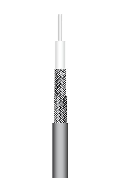
Flexible cable 2.6/50 D (RD316)
P/N: C291 185 067
APPLICATION NOTE
Based on the RG 316 construction, RD316 has an outer shield braid which allows higher screening effectiveness and better mechanical resistance.
Suitable for severe thermal conditions, this cable is compatible with a large range of connector series.
CONSTRUCTION / DIMENSIONS
ELECTRICAL CHARACTERISTICS
ELECTRICAL CHARACTERISTICS Characteristic
MECHANICAL CHARACTERISTICS
MECHANICAL CHARACTERISTICS
(1) SPCCS = Silver Plated Copper covered steel (2) PTFE = PolyTetraFluoroEthylene
(3) SPC = Silver Plated Copper
(4) FEP = Fluorinated Ethylene Propylene
Note:
Typical attenuation for a couple of connectors (dB) = 0.045 x √f (GHz)
ENVIRONMENTAL CHARACTERISTICS
Halogen free No
FREQUENCY / ATTENUATION (typ.) / CW MAX POWER (sea level / 25 °C)
Attenuation calculation (dB/m) (0.82 x √f GHz) + (0.04 x f GHz) Power calculation (W) 130 / √f GHz
(1) SPC = Silver Plated Copper (2) PTFE = PolyTetraFluoroEthylene (3) FEP = Fluorinated Ethylene Propylene
18-12 Go online for data sheets & assembly instructions. Visit www.radiall.com and enter the part number. SIMPLIFICATION IS OUR INNOVATION
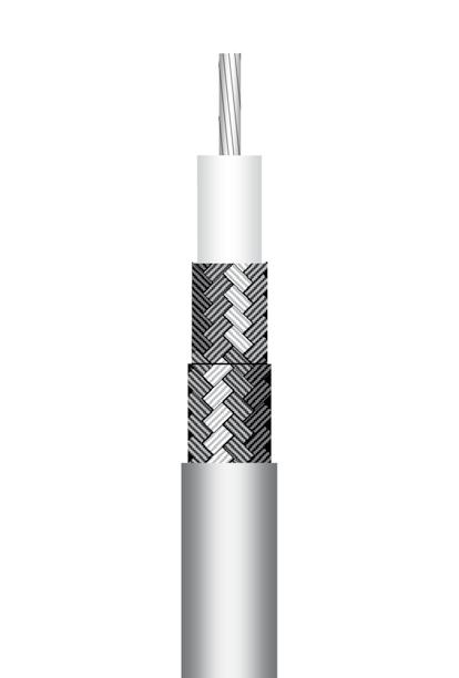
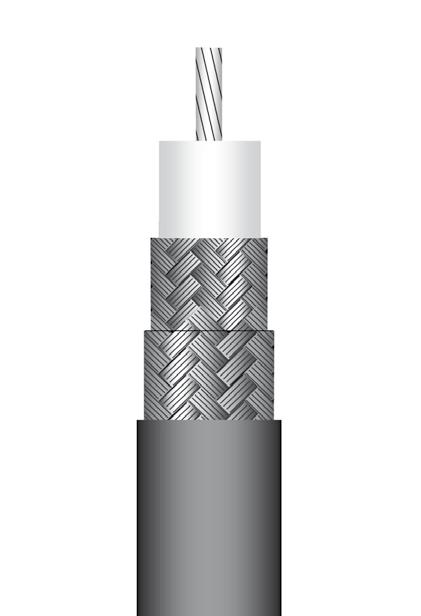
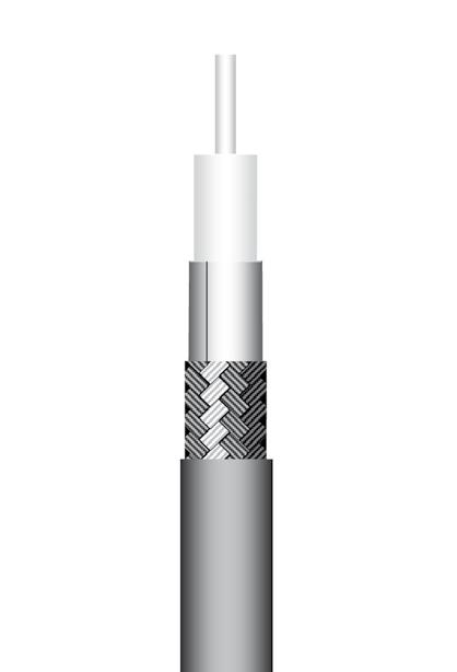
Material mm Inches Center conductor Stranded SPCCS(1) 0.53 0.021 Dielectric Solid PTFE(2) 1.52 0.060 Inner shield SPC(3) braid 1.98 0.078 Outer shield - -Jacket Brown FEP(4) 2.49 0.098
Characteristic impedance 50Ω ± 2Ω Operating frequency range DC - 3 GHz Shielding effectiveness 40 dB Voltage withstanding 2 000 V rms Peak power 1.8 kW Capacitance 96 pF / m 29 pF / ft Velocity of propagation 70 % (4.8 ns / m)
Recommended minimum bending radius 10 mm 0.394 inch Weight 17 g / m 0.0110 Ibs / ft ENVIRONMENTAL
Operating temperature range -55 / +200 °C -67 / +392 °F Fire resistance Yes (CSA FT6 / IEC 332-2) Halogen free No
ATTENUATION
CW MAX POWER (sea level / 25 °C) GHz dB / m dB / ft Watts 0.1 0.26 0.08 411 0.2 0.37 0.11 291 0.3 0.46 0.14 237 0.5 0.60 0.18 184 1.0 0.86 0.26 130 1.5 1.06 0.32 106 2.0 1.24 0.38 92 2.5 1.40 0.42 82 3.0 1.54 0.47 75 Attenuation calculation (dB/m) (0.82 x √f GHz) + (0.04 x f GHz) Power calculation (W) 130 / √f GHz
CHARACTERISTICS
FREQUENCY /
(typ.) /
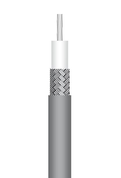
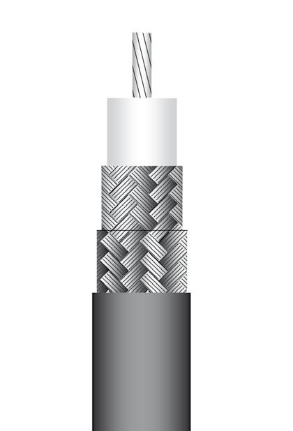
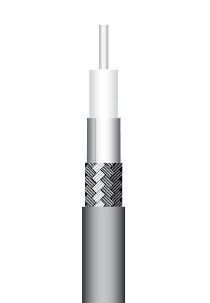
Material mm Inches Center conductor Stranded SPC(1) 0.53 0.021 Dielectric Solid PTFE(2) 1.52 0.060 Inner shield SPC(1) braid 1.90 0.075 Outer shield SPC(1) braid 2.30 0.091 Jacket Brown FEP(3) 2.80 0.110
impedance 50Ω ± 2Ω Operating frequency range DC - 3 GHz Shielding effectiveness 60 dB Voltage withstanding 2 000 V rms Peak power 1.8 kW Capacitance 96 pF / m 29 pF / ft Velocity of propagation 70 % (4.8 ns / m)
Recommended minimum bending radius 15 mm 0.590 inch Weight 27 g / m 0.0181 lbs / ft
temperature range -55 / +200 °C -67 / +392 °F
resistance
(CSA FT6 / IEC 332-2)
Operating
Fire
Yes
GHz dB / m dB / ft Watts 0.1 0.26 0.08 411 0.2 0.37 0.11 291 0.3 0.46 0.14 237 0.5 0.60 0.18 184 1.0 0.86 0.26 130 1.5 1.06 0.32 106 2.0 1.24 0.38 92 2.5 1.40 0.42 82 3.0 1.54 0.47 75
Flexible cable 2.6/75 S (RG179)
P/N: C291 210 007
(MIL-C-17/94-RG179)
APPLICATION NOTE
Due to its 75 ohms characteristic impedance, RG179 is dedicated to TV/Video application. Its small internal stranded inner conductor diameter allows high flexibility for easy routing.
Suitable for severe thermal conditions.
CONSTRUCTION / DIMENSIONS
ELECTRICAL CHARACTERISTICS
Characteristic impedance
MECHANICAL CHARACTERISTICS Recommended
ENVIRONMENTAL CHARACTERISTICS
Flexible cable 4.6/75 D (HD 0.6/2.8 - mini RG59 type)
P/N: C291 333 039
APPLICATION NOTE
Due to its 75 ohms characteristic impedance, this cable is dedicated to HDTV/Video applications.
CONSTRUCTION / DIMENSIONS
FREQUENCY / ATTENUATION (typ.) / CW MAX POWER (sea level / 25
ELECTRICAL CHARACTERISTICS
Characteristic
MECHANICAL CHARACTERISTICS
Recommended
ENVIRONMENTAL CHARACTERISTICS
Operating temperature range -20 / +70 °C -4 / +158 °F Fire resistance Yes
FREQUENCY / ATTENUATION (typ.) / CW MAX POWER (sea level / 25 °C)
Attenuation calculation (dB/m) (0.91 x √f GHz) +
(1) SPCCS = Silver Plated Copper Covered Steel
(2) PTFE = PolyTetraFluoroEthylene
(3) SPC = Silver Plated Copper
(4) FEP = Fluorinated Ethylene Propylene
Note: Typical attenuation for a couple of connectors (dB) = 0.045 x √f (GHz)
Attenuation calculation (dB/m) (0.32 x √f GHz) + (0.023 x f GHz)
(1) BC = Bare Copper
(2) PE = PolyEthylene
(3) Al = Aluminum
(4) PES = PolyESter
(5) TC = Tinned Copper
(6) LSZH PE = Low Smoke Zero Halogen PolyEthylene
18-13 Go online for data sheets & assembly instructions. Visit www.radiall.com and enter the part number. SIMPLIFICATION IS OUR INNOVATION
Material mm Inches Center conductor Stranded SPCCS(1) 0.30 0.012 Dielectric Solid PTFE(2) 1.60 0.063 Inner shield SPC(3) braid 2.00 0.079 Outer shield - -Jacket Brown FEP(4) 2.54 0.100
75Ω
Voltage
Peak power
Capacitance
Velocity
70
± 3Ω Operating frequency range DC - 3 GHz Shielding effectiveness 40 dB
withstanding 2 000 V rms
1.6 kW
69 pF / m 21 pF / ft
of propagation
% (4.8 ns / m)
minimum bending radius 10 mm 0.400 inch Weight 14.5 g / m 0.0097 lbs / ft
Operating temperature range -55 / +200 °C -67 / +392 °F Fire resistance Yes (CSA FT6 / IEC 332-2) Halogen free No
GHz dB / m dB / ft Watts 0.1 0.29 0.09 791 0.2 0.41 0.13 559 0.3 0.51 0.15 456 0.5 0.66 0.20 354 1.0 0.95 0.29 250 1.5 1.17 0.36 204 2.0 1.37 0.41 117 2.5 1.54 0.47 158 3.0 1.70 0.51 144
f GHz)
√f GHz
°C)
(0.04 x
Power calculation (W) 250 /
Material mm Inches Center conductor Solid BC(1) 0.60 0.024 Dielectric Foam PE(2) 2.80 0.110 Inner shield Triplex tape Al(3)/PES(4)/Al 2.90 0.114 Outer shield TC(5) braid 3.30 0.130 Jacket Purple LSZH PE(6) 4.60 0.181
impedance 75Ω ± 3Ω
range DC - 3 GHz
Voltage withstanding 1 500 V rms Peak powerCapacitance 56 pF / m 17.07 pF / ft Velocity of propagation 78 % (4.3 ns / m)
Operating frequency
Shielding effectiveness
minimum bending radius 37 mm 1.46 inch Weight 24 g / m 0.0161 lbs / ft
(IEC 60332-1) Halogen free Yes (IEC 60754-1
-2)
&
GHz dB / m dB / ft Watts 0.05 0.073 0.0220.1 0.103 0.0310.5 0.238 0.0720.8 0.305 0.0921.0 0.343 0.1041.5 0.426 0.1292.0 0.499 0.1512.5 0.563 0.1713.0 0.623 0.189
-
CABLE ASSEMBLIES
CABLE ASSEMBLIES
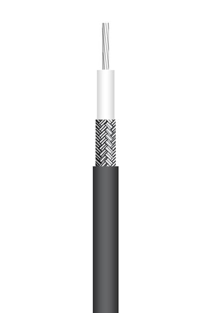
Flexible cable 5/50 S (RG58 - KX15)

P/N: C291 305 000 (MIL-C-17/28-RG58)
P/N: C291 305 010 (NF-C-93/550-KX15)
APPLICATION NOTE
RG58 is one of the most popular RG cables. Due to its construction and raw material construction, RG58 / KX15 is designed to perform the same as 5/50 cables ( RG142, RG223, ECO142 ) This very flexible cable can be considered for applications requiring low electrical performance and reduced cost.
CONSTRUCTION / DIMENSIONS
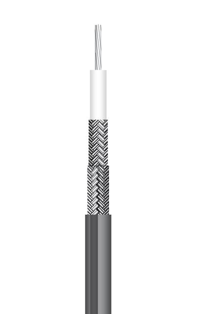
Flexible cable 5/50 D (RG142)
P/N: C291 320 007 (MIL-C-17/158-RG142)
APPLICATION NOTE
RG142 is one of the most popular RG cables. This cable offers a compromise between flexibility and electrical performances. RG142 will be selected among other 5/50 RG's for applications requiring high frequency range and low attenuation.
Suitable for severe thermal conditions.
CONSTRUCTION / DIMENSIONS
ELECTRICAL CHARACTERISTICS
Characteristic impedance
ELECTRICAL CHARACTERISTICS
MECHANICAL CHARACTERISTICS
ENVIRONMENTAL CHARACTERISTICS
MECHANICAL CHARACTERISTICS
(1) TC = Tinned Copper
(2) PE = PolyEthylene
(3) PVC = PolyVinyl Chloride
Note: Typical attenuation for a couple of connectors (dB) = 0.045 x √f (GHz)
ENVIRONMENTAL CHARACTERISTICS
Operating temperature range -55 / +200
Halogen free No
FREQUENCY / ATTENUATION (typ.) / CW MAX POWER (sea level / 25 °C)
Attenuation calculation (dB/m) (0.40 x √f GHz) + (0.04 x f GHz) Power calculation (W) 470 / √f GHz
(1) SPCCS = Silver Plated Copper Covered Steel
(2) PTFE = PolyTetraFluoroEthylene
(3) SPC = Silver Plated Copper
(4) FEP = Fluorinated Ethylene Propylene
18-14 Go online for data sheets & assembly instructions. Visit www.radiall.com and enter the part number. SIMPLIFICATION IS OUR INNOVATION
Material mm Inches Center conductor Stranded TC(1) 0.90 0.035 Dielectric Solid PE(2) 2.95 0.116 Inner shield TC(1) braid 3.66 0.144 Outer shield - -Jacket Black PVC(3) 4.95 0.195
Characteristic impedance 50Ω ± 2Ω Operating frequency range DC - 1 GHz Shielding effectiveness 40 dB Voltage withstanding 5 000 V rms Peak power 2.6 kW Capacitance 96 pF / m 29 pF / ft Velocity of propagation 66 % (5 ns / m)
Recommended minimum bending radius 20 mm 0.787 inch Weight 35 g / m 0.0234 Ibs / ft
Operating temperature range -40 / +85 °C -40 / +185 °F Fire resistance No Halogen free No
ATTENUATION (typ.) / CW MAX POWER (sea level / 25 °C) GHz dB / m dB / ft Watts 0.05 0.14 0.04 246 0.1 0.20 0.06 174 0.2 0.29 0.09 123 0.3 0.36 0.11 100 0.5 0.47 0.14 78 0.6 0.51 0.16 71 0.7 0.56 0.17 66 0.8 0.60 0.18 61 1.0 0.67 0.20 55 Attenuation calculation (dB/m) (0.63 x √f GHz) + (0.04 x f GHz) Power calculation (W) 55 / √f GHz
FREQUENCY /
Material mm Inches Center conductor Solid SPCCS(1) 0.94 0.037 Dielectric Solid PTFE(2) 2.95 0.116 Inner shield SPC(3) braid -Outer shield SPC(3) braid 4.19 0.165 Jacket Brown FEP(4) 4.95 0.195
Operating frequency range DC - 12.4 GHz Shielding effectiveness 65 dB (DC - 3GHz) Voltage withstanding 5 000 V rms Peak power 3.4 kW Capacitance 97 pF / m 29.3 pF / ft Velocity of propagation 70 % (4.8 ns / m)
50Ω ± 2Ω
Recommended minimum bending radius 25 mm 0.984 inch Weight 64 g / m 0.043 Ibs / ft
yes (CSA FT6 / IEC 332-2)
°C -67 / +392 °F Fire resistance
GHz dB / m dB / ft Watts 0.5 0.30 0.09 665 1.0 0.44 0.13 470 1.5 0.55 0.17 384 2.0 0.65 0.20 332 3.0 0.81 0.25 271 6.0 1.22 0.37 192 8.0 1.45 0.44 166 10.0 1.66 0.50 149 12.4 1.90 0.58 133
Flexible cable 5/50 D (RG223)
P/N: C291 330 000 (MIL-C-17/84-RG223)
APPLICATION NOTE
RG223 is one of the most popular RG cables. This cable is a good compromise between flexibility and electrical performance. RG223 can be used instead of RG142 to reduce cost in applications that do not require high temperature resistance.
CONSTRUCTION / DIMENSIONS
APPLICATION NOTE Flexible cable 5/50 D (RG400)
P/N: C291 324 007 (MIL-C-17/128-RG400)
Due to its stranded inner conductor, RG 400 is much more flexible than RG142 and RG223. This cable can be used instead of equivalent RG's for specific applications requiring high flexibility.
Suitable for severe thermal conditions.
CONSTRUCTION / DIMENSIONS
ELECTRICAL CHARACTERISTICS Characteristic
MECHANICAL CHARACTERISTICS
ELECTRICAL CHARACTERISTICS
Characteristic impedance 50Ω ± 2Ω
Operating frequency range DC - 12.4 GHz
Shielding effectiveness 65 dB (DC - 3 GHz)
Voltage withstanding 5 000 V rms
Peak power 3.4 kW Capacitance
MECHANICAL CHARACTERISTICS
Recommended
ENVIRONMENTAL CHARACTERISTICS
FREQUENCY
ENVIRONMENTAL CHARACTERISTICS
Operating temperature range -55 / +200 °C -67 / +392 °F Fire resistance yes (CSA FT6 / IEC 332-2) Halogen free No
FREQUENCY / ATTENUATION (typ.) / CW MAX POWER (sea level / 25 °C)
(2) PE = PolyEthylene
(3) PVC = PolyVinyl Chloride
Attenuation calculation (dB/m) (0.48 x
(1) SPC = Silver Plated Copper (2) PTFE = PolyTetraFluoroEthylene
(3) FEP = Fluorinated
Note:
18-15 Go online for data sheets & assembly instructions. Visit www.radiall.com and enter the part number. SIMPLIFICATION IS OUR INNOVATION
Material mm Inches Center conductor Stranded SPC(1) 0.98 0.039 Dielectric Solid PTFE(2) 2.95 0.116 Inner shield
-Outer shield SPC(1) braid 4.19 0.165 Jacket Brown FEP(3) 4.95 0.195
SPC(1) braid
m 29.3
ft
97 pF /
pF /
Velocity of propagation 70 % (4.8 ns / m)
bending radius 20 mm 0.79 inch Weight 66 g / m 0.0442 lbs / ft
minimum
GHz dB / m dB / ft Watts 0.5 0.36 0.11 665 1.0 0.52 0.16 470 1.5 0.65 0.20 384 2.0 0.76 0.23 332 3.0 0.95 0.29 271 6.0 1.42 0.43 192 8.0 1.68 0.51 166 10.0 1.92 0.58 149 12.4 2.19 0.66 133
GHz)
√f GHz
√f GHz) + (0.04 x f
Power calculation (W) 470 /
Ethylene Propylene
Material mm Inches Center conductor Solid SPC(1) 0.89 0.035 Dielectric Solid PE(2) 2.95 0.116 Inner shield SPC(1) braid -Outer shield SPC(1) braid 4.19 0.165 Jacket Black PVC(3) 5.38 0.212
impedance 50Ω
2Ω Operating frequency range DC - 12.4 GHz Shielding effectiveness 65 dB (DC - 3 GHz) Voltage withstanding 5 000 V rms Peak power 2.6 kW Capacitance 96 pF / m 29 pF / ft Velocity of propagation 66 % (5 ns / m)
±
Recommended minimum bending radius 25 mm 0.984 inch Weight 55 g / m 0.0370 lbs / ft
temperature range -40
°C
Operating
/ +85
-40 / +185 °F Fire resistance No Halogen free No
CW MAX POWER (sea level / 25 °C) GHz dB / m dB / ft Watts 0.5 0.32 0.10 71 1.0 0.46 0.14 50 1.5 0.57 0.17 41 2.0 0.67 0.20 35 3.0 0.85 0.26 29 6.0 1.27 0.38 20 8.0 1.51 0.46 18 10.0 1.73 0.52 16 12.4 1.97 0.60 14 Attenuation calculation
x √f GHz)
f GHz) Power calculation
50 / √f GHz
Copper
/ ATTENUATION (typ.) /
(dB/m) (0.42
+ (0.04 x
(W)
(1) SPC = Silver Plated
ASSEMBLIES
Typical attenuation for a couple of connectors (dB) = 0.045 x √f (GHz) CABLE
CABLE ASSEMBLIES
Flexible cable 5/50 D (KX23)
P/N: C291 322 017
(NF-C-93/550-KX23)
APPLICATION NOTE
Relevant standard: NF-C-93/550-KX23 (France)
Due to its stranded inner conductor it is much more flexible than RG142 or RG223. This cable can be used instead of equivalent RG's for specific applications requiring high flexibility.
Suitable for severe thermal conditions.
CONSTRUCTION / DIMENSIONS
Flexible cable 6/75 S (RG59)
P/N: C291 360 000 (MIL-C-17/29-RG59)
APPLICATION NOTE
Due to its 75 ohms characteristic impedance, RG59 is best suited for TV/ Video application.
Its solid inner conductor allows better attenuation than the equivalent KX solution (KX6).
CONSTRUCTION / DIMENSIONS
ELECTRICAL CHARACTERISTICS
MECHANICAL CHARACTERISTICS
ENVIRONMENTAL CHARACTERISTICS
FREQUENCY / ATTENUATION (typ. / 25 °C) / CW MAX POWER (sea level
ELECTRICAL CHARACTERISTICS
Attenuation calculation (dB/m) (0.427
(1) SPC = Silver Plated Copper (2) PTFE = PolyTetraFluoroEthylene
Note: Typical attenuation for a couple of connectors (dB) = 0.045 x √f (GHz)
ENVIRONMENTAL CHARACTERISTICS
Fire resistance No Halogen free No
FREQUENCY / ATTENUATION (typ.) / CW
Power calculation (W) 75 / √f GHz
(1) CCS = Copper Covered Steel
(2) PE = PolyEthylene
(3) PVC = PolyVinyl Chloride
18-16 Go online for data sheets & assembly instructions. Visit www.radiall.com and enter the part number. SIMPLIFICATION IS OUR INNOVATION
Material mm Inches Center conductor Stranded SPC(1) 0.92 0.036 Dielectric Solid PTFE(2) 2.95 0.116 Inner shield SPC braid -Outer shield SPC braid 4.34 0.171 Jacket Translucent fiber glass 5.10 0.201
impedance 50Ω ± 2.5Ω Operating frequency range DC - 8 GHz Shielding effectiveness 65 dB (DC - 3 GHz) Voltage withstanding 5 000 V rms Peak power 3 kW Capacitance 95 pF / m 28.8 pF / ft Velocity of propagation 70 % (4.8 ns / m)
Characteristic
Recommended minimum bending radius 30 mm 1.181 inch Weight 70 g / m 0.0466 lbs / ft
Operating temperature range -55 / +200 °C -67 / +392 °F Fire resistance Yes (IEC 60332-1) Halogen free No
40 °C) GHz dB / m dB / ft Watts 0.5 0.33 0.10 375 1.0 0.48 0.14 260 1.5 0.60 0.18 210 2.0 0.70 0.21 180 2.5 0.80 0.24 160 3.0 0.89 0.27 146 4.0 1.05 0.32 126 5.0 1.20 0.37 112 6.0 1.35 0.41 102 8.0 1.61 0.49 88
x √f GHz) + (0.05 x f GHz)
/
Material mm Inches Center conductor Solid CCS(1) 0.57 0.022 Dielectric Solid PE(2) 3.71 0.146 Inner shield Copper braid 4.50 0.177 Outer shield - -Jacket Black PVC(3) 6.15 0.242
Characteristic
75Ω ± 3Ω Operating frequency range DC - 1 GHz Shielding effectiveness 40 dB Voltage withstanding 7 000 V rms Peak power 2.7 kW Capacitance 60 pF / m 18.2 pF / ft Velocity of propagation 66 % (5 ns / m)
impedance
Recommended minimum bending radius 30 mm 1.18 inch Weight 47 g / m 0.0315 lbs / ft
MECHANICAL CHARACTERISTICS
Operating temperature range -40 / +85 °C -40 / +185 °F
GHz dB / m dB / ft Watts 0.05 0.09 0.03 335 0.1 0.13 0.04 237 0.2 0.19 0.06 168 0.3 0.23 0.07 137 0.5 0.30 0.09 106 0.6 0.33 0.10 97 0.7 0.36 0.11 90 0.8 0.39 0.12 84 1.0 0.44 0.13 75
√f GHz)
f GHz)
MAX POWER (sea level / 25 °C)
Attenuation calculation (dB/m) (0.40 x
+ (0.04 x
Flexible cable 6/75 S (KX6A)
C291 351 012
APPLICATION NOTE
Relevant standard: NF-C-93/550-KX6 (France)
Due to its stranded inner conductor, KX6 is much more flexible than RG59. This cable is better suited instead of RG59 for specific applications requiring high flexibility.
CONSTRUCTION / DIMENSIONS
ELECTRICAL CHARACTERISTICS
Flexible cable 6/75 D (HD 0.8/3.7 - RG59 type)

P/N: C291 360 093
APPLICATION NOTE
Due to its 75 ohms characteristic impedance, this cable is best suited for HDTV/Video application.
CONSTRUCTION / DIMENSIONS
CHARACTERISTICS
ENVIRONMENTAL CHARACTERISTICS
ELECTRICAL CHARACTERISTICS
Characteristic impedance
Operating frequency range
Shielding effectiveness
withstanding
pF / m 16.3 pF / ft Velocity of propagation 83 % (4.0
MECHANICAL CHARACTERISTICS
Recommended
ENVIRONMENTAL CHARACTERISTICS
Operating temperature range -30 / +75 °C -22 / +167 °F
Fire resistance Yes (UL1666 Vertical Shaft)
Halogen free No
FREQUENCY / ATTENUATION (typ.) / CW MAX POWER (sea level / 25 °C)
Attenuation calculation (dB/m) (0.24 x √f GHz) + (0.007 x f GHz)
Note:
18-17 Go online for data sheets & assembly instructions. Visit www.radiall.com and enter the part number. SIMPLIFICATION IS OUR INNOVATION
Material mm Inches Center conductor Stranded copper 0.60 0.024 Dielectric Solid PE(1) 3.70 0.146 Inner shield Copper braid 4.50 0.177 Outer shield - -Jacket Green PVC(2) 6.10 0.240
impedance 75Ω ± 3Ω Operating frequency range DC - 1 GHz Shielding effectiveness 40 dB Voltage withstanding 7 000 V rms Peak power 2.7 kW Capacitance 63 pF / m 19 pF / ft Velocity of propagation 66 % (5 ns / m)
Recommended minimum bending radius 25 mm 0.98 inch Weight 48 g / m 0.0320 lbs / ft
Characteristic
MECHANICAL
Operating temperature range -40 / +85 °C -40 / +185 °F Fire resistance No Halogen free No FREQUENCY
/ CW MAX POWER (sea level / 25 °C) GHz dB / m dB / ft Watts 0.05 0.10 0.03 300 0.1 0.14 0.04 212 0.2 0.20 0.06 150 0.3 0.25 0.08 122 0.5 0.33 0.10 95 0.6 0.36 0.11 86 0.7 0.40 0.12 80 0.8 0.43 0.13 75 1.0 0.48 0.15 67 Attenuation calculation (dB/m) (0.44 x √f GHz) + (0.04 x f GHz) Power calculation (W) 67 / √f GHz (1) PE = PolyEthylene
PVC
PolyVinyl Chloride Cost effective solution
/ ATTENUATION (typ.)
(2)
=
P/N:
(NF-C-93/550-KX6)
Material mm Inches Center conductor Solid BC(1) 0.81 0.032 Dielectric FHD PE(2) 3.68 0.145 Inner shield Al(3) tape 3.81 0.150 Outer shield TC(4) braid 4.37 0.172 Jacket Blue PVC(5) 5.92 0.233
75Ω
± 1.5Ω
DC
- 4.5 GHz
-
300
-
ns / m)
Voltage
V rms Peak power
Capacitance 53.5
bending radius 63.5 mm 2.5 inch Weight 46 g / m 0.031 lbs / ft
minimum
GHz dB / m dB / ft Watts 0.5 0.173 0.052
1.0 0.247 0.075
1.5 0.304 0.092
2.0 0.353 0.1072.5 0.397 0.1203.0 0.437 0.132
3.5 0.473 0.143
4.0 0.508 0.154
4.5 0.541
-
-
-
-
-
-
0.164 -
(1) BC = Bare Copper (2) FHD PE = Foam High Density PolyEthylene (3) Al = Aluminum (4) TC = Tinned Copper (5) PVC = PolyVinyl Chloride
Typical attenuation
a couple of connectors (dB)
0.045 x √f (GHz)
for
=
CABLE ASSEMBLIES
CABLE ASSEMBLIES
Flexible cable 7/75 D (HD 1.0/4.8 - RG6 type)
P/N: C291 384 083
APPLICATION NOTE
Due to its 75 ohms characteristic impedance, this cable is rbetter suited for HDTV/Video application.
CONSTRUCTION / DIMENSIONS
Flexible cable 10/50 S (RG213 - KX4)
P/N: C291 510 000 (MIL-C-17/74-RG213)
P/N: C291 510 010 (NF-C-93/550-KX4)
Due to its construction and raw material selection, RG213 is a cost effectiveness solution in the 10 mm cable range. This cable may be considered for low frequency applications that do not require a high level of screening effectiveness. APPLICATION NOTE
CONSTRUCTION / DIMENSIONS
ELECTRICAL CHARACTERISTICS
MECHANICAL CHARACTERISTICS
ENVIRONMENTAL CHARACTERISTICS
ELECTRICAL CHARACTERISTICS
FREQUENCY / ATTENUATION (typ.) / CW MAX POWER (sea level / 25 °C)
MECHANICAL CHARACTERISTICS
ENVIRONMENTAL CHARACTERISTICS Operating
Fire resistance No
Halogen free No
FREQUENCY / ATTENUATION (typ.) / CW MAX POWER (sea level / 25 °C)
Note:
18-18 Go online for data sheets & assembly instructions. Visit www.radiall.com and enter the part number. SIMPLIFICATION IS OUR INNOVATION
Material mm Inches Center conductor Solid BC(1) 1.02 0.040 Dielectric FHD PE(2) 4.56 0.180 Inner shield Al(3) tape 4.70 0.185 Outer shield TC(4) braid 5.26 0.207 Jacket Blue PVC(5) 6.95 0.274
Characteristic impedance 75Ω ± 1.5Ω Operating frequency range DC - 4.5 GHz Shielding effectivenessVoltage withstanding 300 V rms Peak powerCapacitance 53.15 pF / m 16.2 pF / ft Velocity of propagation 82 % (4.1 ns / m)
Recommended minimum bending radius 69.85 mm 2.75 inch Weight 59.5 g / m 0.04 lbs / ft
Operating temperature range -30 / +75 °C -22 / +167 °F Fire resistance Yes (UL1666 Vertical Shaft) Halogen free No
GHz dB / m dB / ft Watts 0.5 0.134 0.0401.0 0.193 0.0581.5 0.240 0.0732.0 0.281 0.0852.5 0.318 0.096
3.0 0.352 0.107
3.5 0.384 0.116
4.0 0.414 0.125
4.5 0.443 0.134
+ (0.014 x f GHz) (1) BC = Bare Copper (2) FHD PE = Foam High Density PolyEthylene (3) Al = Aluminum
TC = Tinned Copper (5) PVC = PolyVinyl Chloride
-
-
-
-
Attenuation calculation (dB/m) (0.179 x √f GHz)
(4)
Cost effective solution
Material mm Inches Center conductor Standed copper 2.26 0.089 Dielectric Solid PE(1) 7.24 0.285 Inner shield Copper braid 8.13 0.320 Outer shield - -Jacket Black PVC(2) 10.30 0.406
Characteristic impedance 50Ω ± 2Ω Operating frequency range DC - 1 GHz Shielding effectiveness 40 dB Voltage withstanding 10 000 V rms Peak power 6.5 kW Capacitance 96 pF / m 29 pF / ft Velocity of propagation 66 % (5 ns / m)
Recommended minimum bending radius 40 mm 1.57 inch Weight 148 g / m 0.0999 lbs / ft
temperature range -40 / +85 °C -40 / +185 °F
GHz dB / m dB / ft Watts 0.05 0.05 0.01 805 0.1 0.07 0.02 569 0.2 0.10 0.03 402 0.3 0.12 0.04 329 0.5 0.16 0.05 255 0.6 0.18 0.05 232 0.7 0.20 0.06 215 0.8 0.21 0.06 201 1.0 0.24 0.07 180
(0.20 x √f GHz) + (0.04 x f GHz) Power calculation (W) 180 / √f GHz (1) PE = PolyEthylene (2) PVC = PolyVinyl Chloride
Attenuation calculation (dB/m)
attenuation for a couple of connectors (dB) = 0.045 x √f (GHz)
Typical
Flexible cable 10/50 D (RG393)
P/N: C291 511 007
(MIL-C-17/174-RG393)
APPLICATION NOTE
RG393 is one of the most popular RG cables.
This cable may be used for high frequency range and severe thermal conditions applications.
CONSTRUCTION / DIMENSIONS
ELECTRICAL CHARACTERISTICS
Characteristic impedance 50Ω ± 2Ω
Operating frequency range DC - 11 GHz
Shielding effectiveness 65 dB (DC - 3 GHz)
Voltage withstanding 10 000 V rms
MECHANICAL CHARACTERISTICS
Recommended
ENVIRONMENTAL CHARACTERISTICS
Fire resistance Yes (CSA FT6 / IEC 332-2) Halogen free No
FREQUENCY / ATTENUATION (typ.) / CW
Flexible
cable 11/50 D (RG214 - KX13)
CONSTRUCTION
P/N: C291 600 000 (MIL-C-17/75-RG214)
P/N: C291 600 010 (NF-C-93/550-KX13)
APPLICATION NOTE
RG214 is one of the most popular RG cables. To reduce cost when thermal conditions allow this cable may be used instead of RG393.
/ DIMENSIONS
ELECTRICAL CHARACTERISTICS
Characteristic impedance 50Ω ± 2Ω
Operating frequency range DC - 11 GHz
Shielding effectiveness 65 dB (DC - 3 GHz)
Voltage withstanding
MECHANICAL CHARACTERISTICS Recommended
ENVIRONMENTAL CHARACTERISTICS
Operating temperature range
Fire resistance No Halogen free No
FREQUENCY / ATTENUATION (typ.) / CW MAX POWER (sea level / 25 °C)
CABLE ASSEMBLIES
Attenuation calculation (dB/m) (0.19
PTFE = PolyTetraFluoroEthylene (3) FEP = Fluorinated Ethylene Propylene
Attenuation calculation (dB/m) (0.20 x √f GHz) + (0.04 x F GHz) Power calculation (W) 180 / √f GHz
Note:
18-19 Go online for data sheets & assembly instructions. Visit www.radiall.com and enter the part number. SIMPLIFICATION IS OUR INNOVATION
Material mm Inches Center conductor Stranded SPC(1) 2.39 0.094 Dielectric Solid PTFE(2) 7.24 0.285 Inner shield
-Outer shield
braid 8.90 0.350 Jacket Brown FEP(3) 9.91 0.390
SPC(1) braid
SPC(1)
Velocity
Peak power 8.3 kW Capacitance 96 pF / m 29 pF / ft
of propagation 70 % (4.8 ns / m)
radius 40 mm 1.57 inch Weight 235 g / m 0.1567 lbs / ft
minimum bending
°F
Operating temperature range -55 / +200 °C -67 / +392
MAX POWER
GHz dB / m dB / ft Watts 0.5 0.15 0.05 1 273 1.0 0.23 0.07 900 1.5 0.29 0.09 735 2.0 0.35 0.11 636 3.0 0.45 0.14 520 6.0 0.71 0.21 367 8.0 0.86 0.26 318 10.0 1.00 0.30 285 11.0
271
(sea level / 25 °C)
1.07 0.32
x √f GHz) + (0.04 x f GHz) Power calculation (W) 900 / √f GHz
Copper
(1) SPC = Silver Plated
(2)
Material mm Inches Center conductor Standed SPC(1) 2.25 0.089 Dielectric Solid PE(2) 7.24 0.285 Inner shield SPC(1) braid -Outer shield SPC(1) braid 8.89 0.350 Jacket Black PVC(3) 10.80 0.425
10 000 V rms Peak power 6.5 kW Capacitance 96 pF / m 29 pF / ft Velocity of propagation 66 % (5 ns / m)
minimum bending radius 40 mm 1.57 inch Weight 174 g / m 0.1170 lbs / ft
-40
°C -40 / +185 °F
/ +85
GHz dB / m dB / ft Watts 0.5 0.16 0.05 255 1.0 0.24 0.07 180 1.5 0.30 0.09 147 2.0 0.36 0.11 127 3.0 0.47 0.14 104 6.0 0.73 0.22 73 8.0 0.89 0.27 64 10.0 1.03 0.31 57 11.0 1.10 0.33 54
(1) SPC = Silver Plated Copper (2) PE = PolyEthylene (3) PVC = PolyVinyl Chloride
Typical attenuation for a couple of connectors
0.045
√f (GHz)
(dB) =
x
CABLE ASSEMBLIES
Flexible cable 11/75 D (RG216)
P/N: C291 610 000 (MIL-C-17/77-RG216)
APPLICATION NOTE
Due to its 75 ohms characteristic impedance, RG 216 is better suited for TV/Video applications.
CONSTRUCTION / DIMENSIONS
ELECTRICAL CHARACTERISTICS
MECHANICAL CHARACTERISTICS
ENVIRONMENTAL CHARACTERISTICS
Flexible cable 2.6/50 S (ECO316: alternative to RG316)
ECO-Friendly cable Cost effective solution
P/N: C291 999 904
APPLICATION NOTE
Designed by RADIALL, ECO316 is an advantageous alternative solution to RG316:
• Advantageous in term of electrical performance: its optimized construction allows better attenuation and screening effectiveness than RG316 and RG 174.
• Environmental advantages: halogen and sulphur free, this cable does not emit any toxic substance when submitted to fire. The flame retardant jacket allows ECO316 to meet fire resistance standards.
• Advantageous in term of price: ECO316 design has integrated all Radiall knowledge to reach the best performance with a very competitive price.
ECO316 is UL style 1375 approved. This cable is compatible with a large range of connector series.
CONSTRUCTION / DIMENSIONS
ELECTRICAL CHARACTERISTICS
MECHANICAL CHARACTERISTICS
ENVIRONMENTAL CHARACTERISTICS
FREQUENCY / ATTENUATION (typ.) / CW MAX POWER (sea level / 25 °C)
Note:
18-20 Go online for data sheets & assembly instructions. Visit www.radiall.com and enter the part number. SIMPLIFICATION IS OUR INNOVATION
Material mm Inches Center conductor Stranded TC(1) 1.21 0.048 Dielectric Solid PE(2) 7.24 0.285 Inner shield Copper braid -Outer shield Copper braid 8.89 0.350 Jacket Black PVC(3) 10.80 0.425
Characteristic impedance 75Ω ± 3Ω Operating frequency range DC - 3 GHz Shielding effectiveness 65 dB Voltage withstanding 10 000 V rms Peak power 5.3 kW Capacitance 66 pF / m 20 pF / ft Velocity of propagation 66 % (5 ns / m)
Recommended minimum bending radius 50 mm 1.97 inch Weight 165 g / m 0.1104 lbs / ft
Operating temperature range -40 / +85 °C -40 / +185 °F Fire resistance No Halogen free No FREQUENCY / ATTENUATION (typ.) / CW MAX POWER (sea level / 25 °C) GHz dB / m dB / ft Watts 0.1 0.09 0.03 395 0.2 0.13 0.04 280 0.3 0.17 0.05 228 0.5 0.22 0.07 177 1.0 0.32 0.10 125 1.5 0.40 0.12 102 2.0 0.48 0.14 88 2.5 0.54 0.16 79 3.0 0.60 0.18 72 Attenuation calculation (dB/m) (0.28 x √f GHz) + (0.04 x f GHz) Power calculation (W) 125 / √f GHz
TC
Tinned Copper
PE = PolyEthylene (3) PVC = PolyVinyl Chloride
(1)
=
(2)
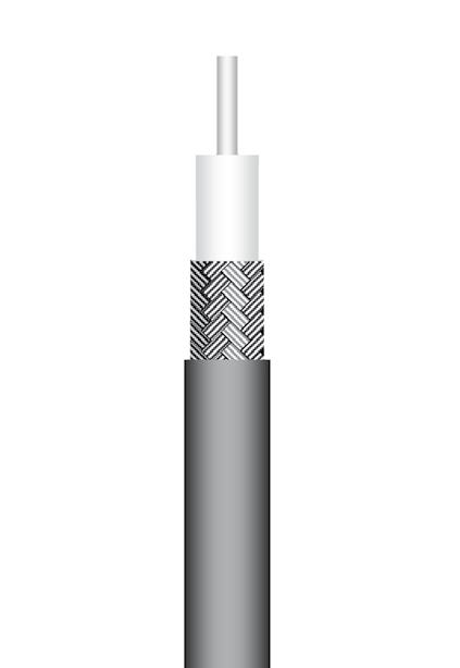
Material mm Inches Center conductor Solid OFC(1) 0.55 0.022 Dielectric Foam PE(2) 1.55 0.061 Inner shield OFC(1) braid 1.90 0.075 Outer shield - -Jacket Black LSZH PE(3) 2.45 0.096
Characteristic impedance 50Ω ± 2Ω Operating frequency range DC - 3 GHz Shielding effectiveness 50 dB Voltage withstanding 2 000 V rms Peak power 1.4 kW Capacitance 84 pF / m 25.5 pF / ft Velocity of propagation 80 % (4.15 ns / m)
Recommended minimum bending radius 15 mm 0.590 inch Weight 10 g / m 0.0066 Ibs / ft
Operating temperature range -40 / +85 °C -40 / +185 °F Fire resistance Yes (UL1581 VW1 / IEC 332-1) Halogen free
(IEC 754-2)
Yes
GHz dB / m dB / ft Watts 0.1 0.24 0.07 120 0.2 0.33 0.10 85 0.3 0.41 0.12 69 0.5 0.53 0.16 54 1.0 0.76 0.23 38 1.5 0.94 0.28 31 2.0 1.09 0.33 27 2.5 1.22 0.37 24 3.0 1.34 0.41 22 Attenuation calculation (dB/m) (0.74 x √f GHz) + (0.02 x f GHz) Power calculation (W) 38 / √f GHz (1) OFC
Oxygen Free Copper (2) PE
(3) LSZH PE
Low Smoke Zero Halogen PolyEthylene
=
= PolyEthylene
=
Typical attenuation for a couple of connectors (dB)
0.045 x √f
GHz)
=
(
ECO-Friendly cable Cost effective solution
P/N:
C291 171 083
APPLICATION NOTE
Designed by Radiall, ECO316X is an alternative solution to ECO316 when higher power level is required:
• Advantageous in term of electrical performance: the crosslink foam polyethylene used as dielectric material allows higher temperature level (thus power range) than ECO316.
• Environmental advantages:: halogen and sulphur free, this cable does not emit any toxic substance when submitted to fire. The flame retardant jacket allows ECO316X to meet fire resistance standards.
• Advantageous in term of price: ECO316X design has integrated all Radiall knowledge to reach the best performance with a very competitive price.
ECO316X is UL style 1375 and 3651 approved This cable is compatible with a large range of standard connector series.
CONSTRUCTION / DIMENSIONS
ELECTRICAL CHARACTERISTICS
Characteristic impedance 50Ω ± 2Ω Operating frequency range DC - 3 GHz
Flexible cable 2.6/50 D (ECO316D: alternative to RD316)
ECO-Friendly cable Cost effective solution
P/N: C291 999 905
APPLICATION NOTE
Designed by Radiall, ECO316D is an alternative solution to RD316:
• Advantageous in term of electrical performance: its optimized construction allows better attenuation and screening effectiveness than RD316.
• Environmental advantages: halogen and sulphur free, this cable does not emit any toxic substance when submitted to fire. The flame retardant jacket allows ECO316D to meet fire resistance standards.
• Advantageous in term of price: ECO316D design has integrated all Radiall knowledge to reach the best performance with a very competitive price.
ECO316D is UL style 1375 approved. This cable is compatible with a large range of connector series.
CONSTRUCTION / DIMENSIONS
ELECTRICAL CHARACTERISTICS
CABLE ASSEMBLIES
MECHANICAL CHARACTERISTICS Recommended
ENVIRONMENTAL CHARACTERISTICS
Halogen free Yes (IEC 754-2)
FREQUENCY /
MECHANICAL CHARACTERISTICS
ENVIRONMENTAL CHARACTERISTICS
Operating temperature range -40 / +85 °C -40 / +185 °F Fire resistance Yes (UL 1581 VW1 / IEC 332-1) Halogen free Yes (IEC 754-2)
FREQUENCY / ATTENUATION (typ.) / CW MAX POWER (sea level / 25 °C)
(1) SPC = Silver Plated Copper
(2) X foam PE = Crosslink foam PolyEthylene
(3) LSZH PE = Low Smoke Zero Halogen PolyEthylene
Note:
18-21 Go online for data sheets & assembly instructions. Visit www.radiall.com and enter the part number. SIMPLIFICATION IS OUR INNOVATION
Flexible cable 2.6/50 S (ECO316X)
Material mm Inches Center conductor Stranded SPC(1) 0.54 0.021 Dielectric X foam PE(2) 1.54 0.061 Inner shield SPC(1) braid 2.05 0.081 Jacket Blue LSZH PE(3) 2.52 0.099
Shielding
Voltage
Capacitance 94.5 pF / m 28.7 pF
ft Velocity of propagation 71 %
ns / m)
effectiveness 35 dB
withstanding 3 000 V rms
/
(4.7
minimum bending radius 5 mm 0.197 inch Weight 16 g / m 0.011 Ibs / ft
Operating temperature range -40 / +105 °C -40 / +221 °F Fire resistance
332-1)
Yes (UL1581 VW1 / IEC
CW MAX POWER (sea level / 20 °C) GHz dB / m dB / ft Watts 0.1 0.27 0.08 285 0.3 0.49 0.15 164 0.5 0.65 0.20 127 0.6 0.72 0.22 116 0.8 0.84 0.26 101 1.0 0.96 0.29 90 1.5 1.22 0.37 73 2.0 1.45 0.44 64 2.5 1.66 0.50 57 3.0 1.85 0.56 52 Attenuation calculation (dB/m) (0.81 x √f GHz) + (0.15 x f GHz) Power calculation (W) 90 / √f GHz
ATTENUATION (typ.) /
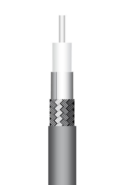
Material mm Inches Center conductor Solid OFC(1) 0.55 0.022 Dielectric Foam PE(2) 1.55 0.061 Inner shield OFC(1) braid 1.90 0.075 Outer shield OFC(1) braid 2.30 0.091 Jacket Black LSZH PE(3) 2.80 0.110
impedance 50Ω ± 2Ω Operating frequency range DC - 3 GHz Shielding effectiveness 65 dB Voltage withstanding 2 000 V rms Peak power 1.4 kW Capacitance 84 pF / m 25.5 pF / ft Velocity of propagation 80 % (4.15 ns / m)
Characteristic
Recommended minimum bending radius 15 mm 0.590 inch Weight 16 g / m 0.0106 lbs / ft
GHz dB / m dB / ft Watts 0.1 0.24 0.07 120 0.2 0.33 0.10 85 0.3 0.41 0.12 69 0.5 0.53 0.16 54 1.0 0.76 0.23 38 1.5 0.94 0.28 31 2.0 1.09 0.33 27 2.5 1.22 0.37 24 3.0 1.34 0.41 22 Attenuation calculation (dB/m) (0.74 x √f GHz) + (0.02 x f GHz) Power calculation (W) 38 / √f GHz (1) OFC = Oxygen Free Copper (2) PE = PolyEthylene (3) LSZH PE = Low Smoke Zero Halogen PolyEthylene
GHz)
Typical attenuation for a couple of connectors (dB) = 0.045 x √f (
CABLE ASSEMBLIES
ECO-Friendly cable Cost effective solution
P/N: C291 217 020
APPLICATION NOTE
Designed by Radiall, ECO316DX is an alternative solution to ECO316D when higher power level is required:
• Advantageous in term of electrical performance: the crosslink foam polyethylene used as dielectric material allows higher temperature level (thus power range) than ECO316D.
• Environmental advantages:: halogen and sulphur free, this cable does not emit any toxic substance when submitted to fire. The flame retardant jacket allows ECO316DX to meet fire resistance standards.
• Advantageous in term of price: ECO316DX design has integrated all Radiall knowledge to reach the best performance with a very competitive price.
ECO316DX is UL style 1375 and 3651 approved.
This cable is compatible with a large range of standard connector series.
CONSTRUCTION / DIMENSIONS
ELECTRICAL CHARACTERISTICS
Flexible cable 5/50 D (ECO142: alternative to RG142)
ECO-Friendly cable Cost effective solution
P/N: C291 325 290
APPLICATION NOTE
Designed by Radiall, ECO142 is an alternative solution to RG142:
• Advantageous in term of electrical performance: its optimized construction allows better attenuation and screening effectiveness than RG142.
• Environmental advantages:: halogen and sulphur free, this cable does not emit any toxic substance when submitted to fire. The flame retardant jacket allows ECO142 to meet fire resistance standards.
• Advantageous in term of price: ECO142 design has integrated all Radiall knowledge to reach the best performance with a very competitive price.
ECO142 is UL style 1375 approved. This cable is compatible with a large range of connector series.
CONSTRUCTION
/ DIMENSIONS
ELECTRICAL CHARACTERISTICS
MECHANICAL CHARACTERISTICS
ENVIRONMENTAL CHARACTERISTICS
MECHANICAL CHARACTERISTICS
ENVIRONMENTAL CHARACTERISTICS
Halogen free Yes (IEC 754-2)
FREQUENCY / ATTENUATION (typ.) / CW MAX POWER (sea level / 25 °C)
(1) SPC = Silver Plated Copper
X foam PE = Crosslink foam PolyEthylene
LSZH PE = Low Smoke Zero Halogen PolyEthylene
Note:
18-22 Go online for data sheets & assembly instructions. Visit www.radiall.com and enter the part number. SIMPLIFICATION IS OUR INNOVATION
Flexible cable 2.6/50 D (ECO316DX)
Material mm Inches Center conductor Stranded SPC(1) 0.54 0.021 Dielectric X foam PE(2) 1.54 0.061 Inner shield SPC(1) braid 2.03 0.080 Outer shield SPC(1) braid 2.50 0.098 Jacket Black with blue stripe LSZH PE(3) 3.16 0.124
Characteristic impedance 50Ω ± 2Ω Operating frequency range DC - 6 GHz Shielding effectiveness 70 dB (DC - 5 GHz) Voltage withstanding 1 500 V rms Capacitance 94.5 pF / m 28.7 pF / ft Velocity of propagation 71 % (4.7 ns / m)
Recommended minimum bending radius 5 mm 0.196 inch Weight 21 g / m 0.0140 Ibs / ft
Operating temperature range -40 / +105 °C -40 / +221 °F Fire resistance
/ IEC 332-1) Halogen free Yes (IEC 754-2) FREQUENCY / ATTENUATION (typ.) / CW MAX POWER (sea level / 25 °C) GHz dB / m dB / ft Watts 0.5 0.58 0.17 127 1.0 0.86 0.26 90 1.5 1.09 0.33 73 2.0 1.30 0.40 64 2.5 1.50 0.45 57 3.0 1.68 0.51 52 3.5 1.85 0.56 48 4.0 2.02 0.61 45 5.0 2.34 0.71 40 6.0 2.64 0.80 37 Attenuation calculation (dB/m) (0.71 x √f GHz) + (0.15 x f GHz) Power calculation (W) 90 / √f GHz
Yes (UL1581 VW1
(2)
(3)
Material mm Inches Center conductor Solid OFC(1) copper 0.95 0.037 Dielectric Foam PE(2) 2.85 0.112 Inner shield Al(3) foil 3.10 0.122 Outer shield TC(4) braid 3.50 0.138 Jacket Black LSZH PE(5) 4.50 0.177
Characteristic impedance 50Ω ± 2Ω Operating frequency range DC - 3 GHz Shielding effectiveness 80 dB (DC - 3 GHz) Voltage withstanding 5 000 V rms Peak power 2.7 kW Capacitance 87 pF / m 26.4 pF / ft Velocity of propagation 77 % (4.3 ns / m)
Recommended minimum bending radius 15 mm 0.590 inch Weight 36 g / m 0.0242 lbs / ft
Operating temperature range -40 / +85 °C -40 / +185 °F Fire resistance Yes (UL1581 VW1 / IEC 332-1)
GHz dB / m dB / ft Watts 0.1 0.12 0.04 411 0.2 0.18 0.05 291 0.3 0.22 0.07 237 0.5 0.28 0.09 184 1.0 0.41 0.12 130 1.5 0.50 0.15 106 2.0 0.58 0.18 92 2.5 0.66 0.20 82 3.0 0.73 0.22 75 Attenuation calculation (dB/m) (0.385 x √f GHz) + (0.02 x f GHz) Power calculation (W) 130 / √f GHz
(1) OFC = Oxygen Free Copper (2) PE = PolyEthylene (3) Al = Aluminum (4) TC = Tinned Copper (5) LSZH PE = Low Smoke Zero Halogen PolyEthylene
Typical attenuation for a couple of connectors (dB)
0.045
√f
GHz)
=
x
(
ECO-Friendly cable Cost effective solution
P/N: C291 320 180
APPLICATION NOTE
Designed by Radiall, ECO142X is an alternative solution to ECO142 when higher power level is required:
• Advantageous in term of electrical performance: the crosslink foam polyethylene used as dielectric material allows higher temperature level (thus power range) than ECO142.
• Environmental advantages:: halogen and sulphur free, this cable does not emit any toxic substance when submitted to fire. The flame retardant jacket allows ECO142X to meet fire resistance standards.
• Advantageous in term of price: ECO142X design has integrated all Radiall knowledge to reach the best performance with a very competitive price.
ECO142X is UL style 1375 and 3651 approved. This cable is compatible with a large range of standard connector series.
CONSTRUCTION / DIMENSIONS
ELECTRICAL CHARACTERISTICS
Characteristic impedance 50Ω ± 2Ω Operating frequency range DC - 6 GHz
effectiveness 75 dB (DC - 5 GHz)
MECHANICAL CHARACTERISTICS
ENVIRONMENTAL CHARACTERISTICS Operating temperature range -40 / +105
-40 / +221 °F Fire resistance Yes (UL1581 VW1 / IEC 332-1)
free Yes (IEC 754-2)
(1) SPC = Silver Plated Copper
(2) X foam PE = Crosslink foam PolyEthylene
(3) LSZH PE = Low Smoke Zero Halogen PolyEthylene
Note: Typical attenuation for a couple of connectors (dB) = 0.045 x √f (GHz)
Flexible cable 5/50 D (Power 142: alternative to RG142)
P/N: C291 325 270
APPLICATION NOTE
Designed by Radiall, POWER142 is an alternative solution to ECO142 when high power level is required:
• Advantageous in term of electrical performance: its optimized construction allows better attenuation and screening effectiveness than RG142 and higher power level than ECO142.
• Environmental advantages:: the flame retardant jacket allows POWER142 to meet fire resistance standards.
• Advantageous in term of price: POWER142 design has integrated all Radiall knowledge to reach the best performance with a very competitive price. POWER142 is UL style 1375 approved. This cable is compatible with a large range of connector series.
CONSTRUCTION / DIMENSIONS
ELECTRICAL CHARACTERISTICS
Characteristic impedance
Operating frequency range
effectiveness
withstanding
MECHANICAL CHARACTERISTICS
ENVIRONMENTAL CHARACTERISTICS
Operating temperature range
Fire resistance Yes (UL1581 VW1 / IEC
Halogen free No
FREQUENCY / ATTENUATION (typ.) / CW MAX POWER (sea level / 40 °C)
CABLE ASSEMBLIES
Attenuation calculation (dB/m) (0.402 x √f GHz) + (0.008 x f GHz)
Power calculation (W) 210 / √f GHz
(1) SPC = Silver Plated Copper
(2) PTFE = PolyTetraFluoroEthylene
(3) Al = Aluminum
(4) TC = Tinned Copper
(5) LSZH PE = Low Smoke Zero Halogen PolyEthylene
18-23 Go online for data sheets & assembly instructions. Visit www.radiall.com and enter the part number. SIMPLIFICATION IS OUR INNOVATION Flexible cable
5/50 D (ECO142X)
Material mm inches
conductor Solid SPC(1)
Dielectric X foam PE(2)
0.117 Inner shield SPC(1) braid 3.64 0.143 Outer shield SPC(1) braid 4.30 0.169 Jacket Black with blue stripe LSZH PE(3) 5.00 0.197
Center
0.95 0.037
2.98
Shielding
Voltage
Capacitance 94.5 pF / m 28.7
ft Velocity of propagation 71 %
m)
withstanding 5 000 V rms
pF /
(4.7 ns /
Recommended minimum bending radius 30 mm 1.18 inch Weight 60 g / m 0.0433 Ibs / ft
Halogen
CW MAX POWER
GHz dB / m dB / ft Watts 0.5 0.36 0.11 354 1.0 0.54 0.16 250 1.5 0.69 0.21 204 2.0 0.83 0.25 177 2.5 0.95 0.29 158 3.0 1.07 0.32 144 3.5 1.18 0.36 134 4.0 1.29 0.39 125 5.0 1.50 0.45 112 6.0 1.70 0.51 102 Attenuation calculation (dB/m) (0.44 x √f GHz) + (0.103 x f GHz) Power calculation (W) 250 / √f GHz
°C
FREQUENCY / ATTENUATION (typ.) /
(sea level / 25 °C)
Material mm Inches Center conductor Solid SPC(1) 0.92 0.036 Dielectric Solid PTFE(2) 2.97 0.117 Inner shield Al(3) foil 3.20 0.126 Outer shield TC(4) braid 3.60 0.142 Jacket Black LSZH PE(5) 4.50 0.177
50Ω ± 2Ω
DC - 3 GHz
Peak
Capacitance 97 pF / m 29.3 pF / ft Velocity of propagation 69 % (4.8 ns / m)
Shielding
90 dB (DC - 3 GHz) Voltage
5 000 V rms
power 3.4 kW
Recommended minimum bending radius 25 mm 0.980 inch Weight 40 g / m 0.0269 lbs / ft
°C -40
°F
-40 / +105
/ +221
332-1)
GHz dB / m dB / ft Watts 0.2 0.18 0.05 470 0.4 0.26 0.08 332 0.6 0.32 0.10 271 0.8 0.37 0.11 235 1.0 0.41 0.12 210 1.5 0.50 0.15 171 2.0 0.58 0.18 148 2.5 0.66 0.20 133 3.0 0.72 0.22 121
CABLE ASSEMBLIES
Flexible cable 6/50 D (ECO230)
P/N: C291 326 490
APPLICATION NOTE
Designed by Radiall, ECO230 is an alternative solution to 5 mm dia. cables when higher power level is required:
• Advantageous in term of electrical performance: its optimized construction allows better attenuation and screening effectiveness than RG cables.
• Environmental advantages:: halogen and sulphur free, this cable does not emit any toxic substance when submitted to fire.
The flame retardant jacket allows ECO230 to meet fire resistance standards.
• Advantageous in term of price: ECO230 design has integrated all Radiall knowledge to reach the best performance with a very competitive price.
ECO230 is UL style 1375 approved.
CONSTRUCTION / DIMENSIONS
ELECTRICAL CHARACTERISTICS
Characteristic impedance 50Ω ± 2Ω
frequency range DC - 4 GHz
effectiveness
dB (DC - 3 GHz)
MECHANICAL CHARACTERISTICS
CHARACTERISTICS Operating temperature range -40 / +85 °C -40 / +185 °F Fire resistance Yes (UL1581 VW1
(1) OFC = Oxygen Free Copper
(2) PE = PolyEthylene
(3) Al = Aluminum
(4) TC = Tinned Copper
(5) LSZH PE = Low Smoke Zero Halogen PolyEthylene
Note:
Typical attenuation for a couple of connectors (dB) = 0.045 x √f (GHz)
Flexible cable 10/50 D (ECO393: alternative to RG393)
ECO-Friendly cable Cost effective solution
P/N: C291 491 060
APPLICATION NOTE
Designed by Radiall, ECO393 is an alternative solution to RG393:
• Advantageous in term of electrical performance: its optimized construction allows better attenuation and screening effectiveness than RG393
• Environmental advantages:: halogen and sulphur free, this cable does not emit any toxic substance when submitted to fire. The flame retardant jacket allows ECO393 to meet fire resistance standards.
• Advantageous in term of price: ECO393 design has integrated all Radiall knowledge to reach the best performance with a very competitive price.
ECO393 is UL style 1375 approved. This cable is compatible with a large range of connector series.
CONSTRUCTION / DIMENSIONS
ELECTRICAL CHARACTERISTICS
MECHANICAL CHARACTERISTICS
ENVIRONMENTAL CHARACTERISTICS
FREQUENCY / ATTENUATION (typ.) / CW MAX POWER (sea level / 25 °C)
(1) OFC = Oxygen Free Copper
(2) PE = PolyEthylene
(3) Al = Aluminum
(4) TC = Tinned Copper
(5) LSZH PE = Low Smoke Zero Halogen PolyEthylene
18-24 Go online for data sheets & assembly instructions. Visit www.radiall.com and enter the part number. SIMPLIFICATION IS OUR INNOVATION
Material mm Inches Center conductor OFC(1) copper 1.46 0.057 Dielectric Foam PE(2) 4.07 0.160 Inner shield Al(3) foil 4.27 0.168 Outer shield TC(4) braid 4.75 0.187 Jacket Black LSZH(5) PE 5.90 0.232
Shielding
Voltage withstanding
Peak power 3.3 kW Capacitance 84 pF / m 25.5 pF / ft Velocity of propagation 79 % (4.2 ns / m)
Operating
90
3 000 V rms
Recommended minimum bending radius 25 mm 0.98 inch Weight 62 g / m 0.0417 lbs / ft
/ IEC 332-1) Halogen free Yes (IEC 754-2) FREQUENCY / ATTENUATION (typ.) / CW MAX POWER (sea level / 40 °C) GHz dB / m dB / ft Watts 0.2 0.12 0.04 391 0.4 0.17 0.05 277 0.6 0.21 0.06 226 0.8 0.25 0.08 196 1.0 0.28 0.08 175 1.5 0.35 0.10 143 2.0 0.40 0.12 124 2.5 0.45 0.14 111 3.0 0.50 0.15 101 4.0 0.59 0.18 88 Attenuation calculation (dB/m) (0.264 x √f GHz) + (0.015 x f GHz) Power calculation (W) 175 / √f GHz
ENVIRONMENTAL
Material mm Inches Center conductor Solid OFC(1) 2.40 0.094 Dielectric Foam PE(2) 7.25 0.285 Inner shield Al(3) foil 7.35 0.289 Outer shield TC(4) braid 7.85 0.309 Jacket Black LSZH PE(5) 9.10 0.358
impedance 50Ω ± 2Ω Operating frequency range DC - 3 GHz Shielding effectiveness 80 dB (DC - 3 GHz) Voltage withstanding 10 000 V rms Peak power 6.6 kW Capacitance 88 pF / m 26.6 pF / ft Velocity of propagation 75 % (4.4 ns / m)
Characteristic
Recommended minimum bending radius 40 mm 1.57 inch Weight 130 g / m 0.0875 lbs / ft
Operating temperature range -40 / +85 °C -40 / +185 °F Fire resistance Yes (UL1581 VW1
IEC 332-1)
754-2)
/
Halogen free Yes (IEC
GHz dB / m dB / ft Watts 0.1 0.05 0.01 1 265 0.2 0.07 0.02 894 0.3 0.08 0.03 730 0.5 0.11 0.03 566 1.0 0.16 0.05 400 1.5 0.20 0.06 327 2.0 0.24 0.07 283 2.5 0.27 0.08 253 3.0 0.30 0.09 231
calculation (dB/m) (0.14 x √f GHz) + (0.02 x f GHz) Power calculation
400 / √f GHz
Attenuation
(W)
Flexible cable 10/50 D (ECO393X)
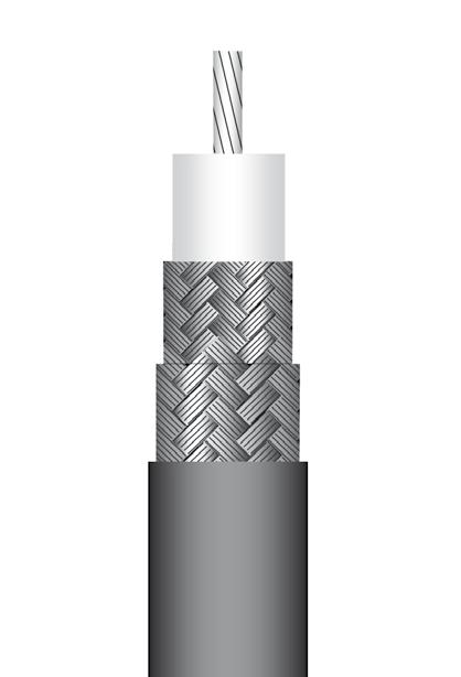
ECO-Friendly cable Cost effective solution
P/N: C291 512 020
APPLICATION NOTE
Designed by Radiall, ECO393X is an alternative solution to ECO393 when higher power level is required:
• Advantageous in term of electrical performance: the crosslink foam polyethylene used as dielectric material allows higher temperature level (thus power range) than ECO393.
• Environmental advantages: halogen and sulphur free, this cable does not emit any toxic substance when submitted to fire. The flame retardant jacket allows ECO393X to meet fire resistance standards.
• Advantageous in term of price: ECO393X design has integrated all Radiall knowledge to reach the best performance with a very competitive price.
ECO393X is UL style 3651 approved. This cable is compatible with a large range of standard connector series.
CONSTRUCTION / DIMENSIONS
ELECTRICAL CHARACTERISTICS
Characteristic impedance 50Ω ± 2Ω
effectiveness
- 6 GHz
dB (DC - 3 GHz)
MECHANICAL CHARACTERISTICS
ENVIRONMENTAL CHARACTERISTICS
Operating temperature range -40 / +105 °C -40 / +221 °F Fire resistance Yes (UL1581 VW1) Halogen free Yes (IEC 754-2)
/ ATTENUATION (typ.) /
(1) SPC = Silver Plated Copper
(2) X foam PE = Crosslink foam PolyEthylene
(3) LSZH PE = Low Smoke Zero Halogen PolyEthylene
Note:
Typical attenuation for a couple of connectors (dB) = 0.045 x √f (GHz)
Corrugated cable 1/4" (Cellflex 1/4" Spiral)
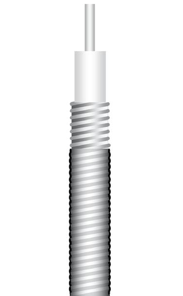
P/N: C291 993 170 (Cellflex HCF 1/4" - 50 AlCu)
APPLICATION NOTE
The outer conductor of this cable is made up of a corrugated tube (spiral winding).
This construction allows perfect shielding and bendability while enabling a large bending radius.
The foam dielectric provides excellent loss and low return loss levels.
This cable will be advised for feeder and jumper assemblies in cellular networks as well as applications requiring high performance level on long distances.
The anti-UV LSZH (Low Smoke Zero Hallogen) material is also flame retardant and allows this cable to be used for indoor public areas as well as outoor installations.
CONSTRUCTION / DIMENSIONS
ELECTRICAL CHARACTERISTICS
Characteristic impedance
effectiveness
withstanding
MECHANICAL CHARACTERISTICS
ENVIRONMENTAL CHARACTERISTICS
Operating temperature range -40 / +85 °C -40 / +185 °F Fire resistance Yes (UL 1581 VW1 / IEC 332-1)
Halogen free Yes (IEC 754-2)
FREQUENCY / ATTENUATION (typ. / 25 °C) / CW MAX POWER (sea level / 40 °C)
Attenuation calculation (dB/m) (0.17 x √f GHz) + (0.015 x f GHz)
AlCC = Aluminum Covered Copper
18-25 Go online for data sheets & assembly instructions. Visit www.radiall.com and enter the part number. SIMPLIFICATION IS OUR INNOVATION
Material mm Inches Center conductor Stranded SPC(1) 2.35 0.093 Dielectric X foam PE(2) 7.20 0.283 Inner shield SPC(1) braid 7.89 0.311 Outer shield SPC(1) braid 8.57 0.337 Jacket Black LSZH PE(3) 10.00 0.394
Shielding
Voltage withstanding 5 000 V rms Capacitance 94 pF / m 28.1 pF / ft Velocity of propagation 71 % (4.7 ns / m)
Operating frequency range DC
78
Recommended minimum bending radius 50 mm 1.97 inch Weight 180 g / m 0.120 Ibs / ft
CW MAX POWER
level
GHz dB / m dB / ft Watts 0.5 0.18 0.05 693 1.0 0.29 0.09 490 1.5 0.38 0.12 400 2.0 0.47 0.14 346 2.5 0.56 0.17 310 3.0 0.64 0.19 283 3.5 0.72 0.22 262 4.0 0.80 0.24 245 5.0 0.96 0.29 219 6.0 1.11 0.34 200 Attenuation calculation (dB/m) (0.17 x √f GHz) + (0.115 x f GHz) Power calculation (W) 490 / √f GHz
FREQUENCY
(sea
/ 25 °C)
Material mm Inches Center conductor Solid AlCC(1) 1.90 0.075 Dielectric Foam PE(2) 4.30 0.169 Corrugated inner shield Spiral copper tube 6.50 0.256 Outer shield - -Jacket Black LSZH PE(3) 7.80 0.307
50Ω
Operating
DC - 20.4 GHz Shielding
110 dB Voltage
3 100 V rms Peak
5.5 kW Capacitance 82
m 24.8 pF / ft Velocity of propagation 82 % (4.1 ns / m)
± 1Ω
frequency range
power
pF /
Recommended minimum bending radius 25.0 mm 0.984 inch Weight 70 g / m 0.047 lb / ft
GHz dB / m dB / ft Watts 1.0 0.19 0.06 339 2.0 0.27 0.08 232 3.0 0.34 0.10 185 4.0 0.40 0.12 156 6.0 0.51 0.15 124 8.0 0.60 0.18 104 10.0 0.69 0.21 91 12.4 0.78 0.24 79 18.0 0.99 0.30 63 20.0 1.06 0.32 59
(1)
(2)
(3)
PE = PolyEthylene
LSZH PE = Low Smoke Zero Hallogen PolyEthylene
CABLE ASSEMBLIES
CABLE ASSEMBLIES
Corrugated cable 3/8" (Cellflex 3/8" Spiral)
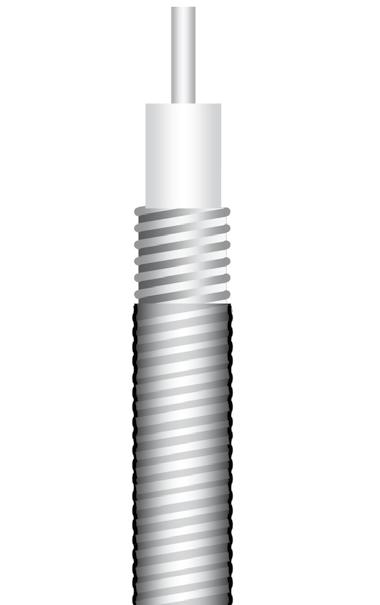
P/N: C291 996 170 (Cellflex HCF 3/8" CuH-50 AlCu)
APPLICATION NOTE
The outer conductor of this cable is made up of a corrugated tube (spiral winding).
This construction allows perfect shielding and bendability while enabling large bending radius.
The foam dielectric provides excellent loss and low return loss levels.
This cable is suitable for feeder and jumper assemblies in cellular networks as well as applications requiring high performance level on long distances.
The anti-UV LSZH (Low Smoke Zero Halogen) material is also flame retardant and allows this cable to be used for indoor public areas as well as outoor installations.
CONSTRUCTION / DIMENSIONS
ELECTRICAL CHARACTERISTICS
MECHANICAL CHARACTERISTICS
ENVIRONMENTAL CHARACTERISTICS
FREQUENCY / ATTENUATION (typ. / 25 °C) /
Corrugated cable 1/2" (Cellflex 1/2" Spiral)
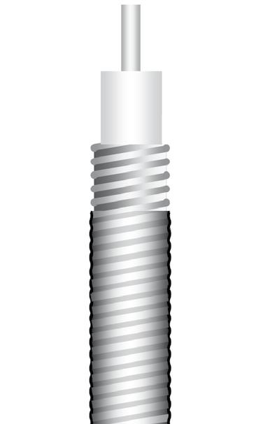
P/N: C291 994 170 (Cellflex HCF 1/2" CuH-50 AlCu)
APPLICATION NOTE
The outer conductor of this cable is made up of a corrugated tube (spiral winding). This construction allows perfect shielding and bendability while enabling large bending radius.
The foam dielectric provides excellent loss and low return loss levels. This cable will be advised for feeder and jumper assemblies in cellular networks as well as applications requiring high performance level on long distances.
The anti-UV LSZH (Low Smoke Zero Halogen) material is also flame retardant and allows this cable to be used for indoor public areas as well as outoor installations.
CONSTRUCTION
/ DIMENSIONS
ELECTRICAL CHARACTERISTICS
(1) AlCC = Aluminum Covered Copper
(2) PE = PolyEthylene
(3) LSZH PE = Low Smoke Zero Hallogen PolyEthylene
Note: Typical attenuation for a couple of connectors (dB) = 0.045 x √f (GHz)
MECHANICAL CHARACTERISTICS
ENVIRONMENTAL CHARACTERISTICS
FREQUENCY / ATTENUATION (typ. / 25 °C) / CW MAX POWER (sea level / 40 °C)
Attenuation calculation (dB/m) (0.10 x √f GHz) + (0.01 x
18-26 Go online for data sheets & assembly instructions. Visit www.radiall.com and enter the part number. SIMPLIFICATION IS OUR INNOVATION
Material mm Inches Center conductor Solid AlCC(1) 2.60 0.102 Dielectric Foam PE(2) 6.30 0.248 Corrugated inner shield Spiral copper tube 9.10 0.358 Outer shield - -Jacket Black LSZH PE(3) 10.20 0.402
Characteristic impedance 50Ω ± 1Ω Operating frequency range DC - 13.4 GHz Shielding effectiveness 110 dB Voltage withstanding 4 500 V rms Peak power 11.9 kW Capacitance 82 pF / m 24.8 pF / ft Velocity of propagation 82 % (4.1 ns / m)
Recommended minimum bending radius 25.0 mm 0.984 inch Weight 120 g / m 0.080 lbs / ft
Operating temperature range -40 / +85 °C -40 / +185 °F Fire resistance Yes (UL 1581 VW1 / IEC 332-1) Halogen free Yes (IEC 754-2)
CW MAX POWER
level
40
GHz dB / m dB / ft Watts 0.5 0.09 0.03 810 1.0 0.13 0.04 560 1.5 0.17 0.05 449 2.0 0.19 0.06 384 3.0 0.24 0.07 306 4.0 0.29 0.09 260 6.0 0.36 0.11 205 8.0 0.43 0.13 173 10.0 0.49 0.15 152 12.4 0.56 0.17 133 Attenuation calculation (dB/m) (0.123 x √f GHz) + (0.01 x f GHz)
(sea
/
°C)
Material mm Inches Center conductor Solid AlCC(1) 3.60 0.142 Dielectric Foam PE(2) 8.30 0.327 Corrugated inner shield Spiral copper tube 12.30 0.484 Outer shield - -Jacket Black LSZH PE(3) 13.50 0.531
Characteristic impedance 50Ω ± 1Ω Operating frequency range DC - 11.7 GHz Shielding effectiveness 110 dB Voltage withstanding 5 845 V rms Peak power 20.5 kW Capacitance 82 pF / m 24.8 pF / ft Velocity of propagation 82 % (4.1 ns / m)
Recommended minimum bending radius 32.0 mm 1.260 inch Weight 210 g / m 0.140 lbs / ft
Operating temperature range -40 / +85 °C -40 / +185 °F Fire resistance Yes (UL 1581 VW1 / IEC 332-1) Halogen free Yes (IEC 754-2)
GHz dB / m dB / ft Watts 0.5 0.08 0.02 1 120 1.0 0.11 0.03 770 1.5 0.14 0.04 616 2.0 0.16 0.05 525 2.5 0.18 0.06 461 3.0 0.20 0.06 417 4.0 0.24 0.07 353 6.0 0.30 0.09 278 8.0 0.36 0.11 234 10.0 0.42 0.13 204
(1)
(2) PE
(3) LSZH PE
Low
Zero Hallogen PolyEthylene
f GHz)
AlCC = Aluminum Covered Copper
= PolyEthylene
=
Smoke
Semi-rigid cable .047 (Copper)
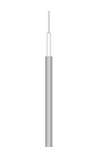
P/N: C291 855 001 (MIL-C-17/151-00001)
APPLICATION NOTE
This is the smallest semi-rigid cable size available through Radiall. Its reduced size allows it to be easily handformable during integration operations.
CONSTRUCTION / DIMENSIONS
ELECTRICAL CHARACTERISTICS
Characteristic
MECHANICAL CHARACTERISTICS
ENVIRONMENTAL CHARACTERISTICS Operating temperature range -40 / +100 °C -40 / +212 °F Fire resistance N/A Halogen
FREQUENCY / ATTENUATION (typ.) /
PTFE = PolyTetraFluoroEthylene
Note:
Typical attenuation for a couple of connectors (dB) = 0.045 x √f (GHz)
Semi-rigid cable .047 (Tinned copper)
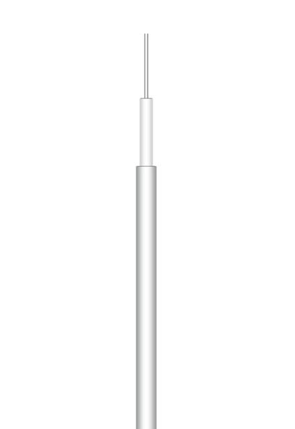
P/N: C291 855 065 (MILC-17/151-00002 TYPE)
APPLICATION NOTE
This is the smallest semi-rigid cable size available at Radiall.
Its reduced size allows it to be easily handformable during integration operations. Due to the outer conductor coating (tin), this cable will be used instead of standard .047 copper for applications requiring high corrosion resistance and improved solderability.
CONSTRUCTION / DIMENSIONS
ELECTRICAL CHARACTERISTICS
Characteristic impedance
MECHANICAL CHARACTERISTICS
ENVIRONMENTAL CHARACTERISTICS
Operating temperature range -40 / +100 °C -40 / +212 °F Fire resistance N/A
Halogen free No
FREQUENCY / ATTENUATION (typ.) / CW MAX POWER (sea level / 25 °C)
CABLE ASSEMBLIES
Attenuation calculation (dB/m) (1.10 x √f GHz) + (0.04 x f GHz) Power calculation (W) 30 / √f GHz
(1) SPCCS = Silver Plated Copper Covered Steel (2) PTFE = PolyTetraFluoroEthylene (3) TC = Tinned Copper
18-27 Go online for data sheets & assembly instructions. Visit www.radiall.com and enter the part number. SIMPLIFICATION IS OUR INNOVATION
Material mm Inches
conductor Solid SPCCS(1) 0.29 0.011 Dielectric Solid PTFE(2) 0.94 0.037 Inner shield Copper tubing 1.19 0.047
shield - -Jacket - - -
Center
Outer
Voltage
2 000
Peak power 1.1 kW Capacitance 100 pF / m 30 pF / ft Velocity of propagation 70 % (4.8 ns / m)
impedance 50Ω ± 2.5Ω Operating frequency range DC - 20 GHz Shielding effectiveness 110 dB
withstanding
V rms
Recommended minimum bending radius 3.17 mm 0.125 inch Weight 6.0 g / m 0.0040 lbs / ft
MAX POWER
GHz dB / m dB / ft Watts 1.0 1.14 0.35 30 2.0 1.64 0.50 21 3.0 2.03 0.61 17 6.0 2.93 0.89 12 8.0 3.43 1.04 11 10.0 3.88 1.18 9.5 12.4 4.37 1.32 8.5 18.0 5.39 1.63 7.1 20.0 5.72 1.73 6.7 Attenuation calculation (dB/m) (1.10 x √f GHz) + (0.04 x f GHz) Power calculation (W) 30 / √f GHz (1) SPCCS = Silver Plated Copper Covered Steel (2)
free No
CW
(sea level / 25 °C)
Material mm Inches Center conductor Solid SPCCS(1) 0.29 0.011 Dielectric Solid PTFE(2) 0.94 0.037 Inner shield TC(3) tubing 1.19 0.047 Outer shield - -Jacket - - -
50Ω ± 2.5Ω
DC - 20 GHz
Operating frequency range
110 dB
2 000 V rms Peak power 1.1 kW Capacitance 100 pF / m 30 pF / ft
70 %
ns
m)
Shielding effectiveness
Voltage withstanding
Velocity of propagation
(4.8
/
minimum bending radius 3.17 mm 0.125 inch Weight 6.0 g / m 0.0040 lbs / ft
Recommended
GHz dB / m dB / ft Watts 1.0 1.14 0.35 30 2.0 1.64 0.50 21 3.0 2.03 0.61 17 6.0 2.93 0.89 12 8.0 3.43 1.04 11 10.0 3.88 1.18 9.5 12.4 4.37 1.32 8.5 18.0 5.39 1.63 7.1 20.0 5.72 1.73 6.7
CABLE ASSEMBLIES
Hand-formable cable .085 (unjacketed)
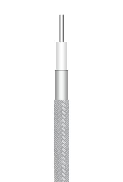
P/N: C291 844 065
APPLICATION NOTE
This handformable cable is the perfect alternative to RG405 for applications requiring an easy routing on equipment. Due to the outer conductor construction, this cable can be hand formed with exceptional ease with no spring back effect.
Cable can be reshaped, eliminating the need for costly drawings.
Attenuation is a little bit higher than RG405 but temperature range is wider.
CONSTRUCTION / DIMENSIONS
CHARACTERISTICS
MECHANICAL CHARACTERISTICS
(1) SPCCS = Silver Plated Copper Covered Steel (2) PTFE = PolyTetraFluoroEthylene
(3) TS = Tin Soaked
(4) one time
(5) repeated
Note: Typical attenuation for a couple of connectors (dB) = 0.045 x √f (GHz)
Semi-rigid cable .085 (RG405 - KS1)

P/N: C291 850 001 (MIL-C-17/133-RG405) (NF-C-93/551-KS1)
APPLICATION NOTE
RG405 is one of the most popular semi-rigid RG cables.
RG405 is a more preferred option to flexible RG316 or RD316 for applications requiring high frequency range, low attenuation, high screening effectiveness, very small bending radius and/or no spring back effect.
CONSTRUCTION / DIMENSIONS
ELECTRICAL CHARACTERISTICS
MECHANICAL CHARACTERISTICS
ENVIRONMENTAL CHARACTERISTICS
Fire resistance N/A
Halogen free No
FREQUENCY / ATTENUATION (typ.) / CW MAX POWER (sea level / 25 °C)
Attenuation calculation (dB/m) (0.61 x √f GHz) + (0.04 x f
(1) SPCCS = Silver Plated Copper Covered Steel
(2) PTFE = PolyTetraFluoroEthylene
18-28 Go online for data sheets & assembly instructions. Visit www.radiall.com and enter the part number. SIMPLIFICATION IS OUR INNOVATION
Material mm Inches Center conductor Solid SPCCS(1) 0.51 0.020 Dielectric Solid PTFE(2) 1.63 0.064 Inner shield copper foil -Outer shield TS(3) braid 2.21 0.087 Jacket - -ELECTRICAL
Characteristic impedance 50Ω ± 2Ω Operating frequency range DC - 20 GHz Shielding effectiveness 90 dB Voltage withstanding 5 000 V rms Peak power 1.9 kW Capacitance 97.5 pF / m 29.5 pF / ft Velocity of propagation 70 % (4.8 ns / m)
Recommended minimum bending radius 3.2(4) / 9.5(5) mm 0.125(4) / 0.375(5) inch Weight 17.8 g / m 0.0119 lbs / ft ENVIRONMENTAL
Operating temperature range -65 / +150 °C -85 / +302 °F Fire resistance N/A Halogen free No
CHARACTERISTICS
CW MAX POWER (sea level / 25 °C) GHz dB / m dB / ft Watts 1.0 0.67 0.20 100 2.0 0.97 0.29 71 3.0 1.21 0.37 58 6.0 1.78 0.54 41 8.0 2.10 0.64 35 10.0 2.39 0.72 32 12.4 2.71 0.82 28 18.0 3.39 1.03 24 20.0 3.62 1.10 22 Attenuation calculation (dB/m) (0.63 x √f GHz) + (0.04 x f GHz) Power calculation (W) 100 / √f GHz
FREQUENCY / ATTENUATION (typ.) /
Material mm Inches Center conductor Solid SPCCS(1) 0.51 0.020 Dielectric Solid PTFE(2) 1.68 0.066 Inner shield Copper tubing 2.20 0.087 Outer shield - -Jacket - - -
50Ω ± 1.5Ω Operating
range DC - 20 GHz Shielding
110 dB Voltage
5 000 V rms Peak power 1.9 kW Capacitance 100 pF / m 30 pF / ft Velocity of propagation 70 % (4.8 ns / m)
Characteristic impedance
frequency
effectiveness
withstanding
Recommended minimum bending radius 3.17 mm 0.125 inch Weight 20.0 g / m 0.0135 lbs / ft
temperature range -40 / +125 °C -40 / +257 °F
Operating
GHz dB / m dB / ft Watts 1.0 0.65 0.20 100 2.0 0.94 0.29 71 3.0 1.18 0.36 58 6.0 1.73 0.53 41 8.0 2.05 0.62 35 10.0 2.33 0.71 32 12.4 2.64 0.80 28 18.0 3.31 1.00 24 20.0 3.53 1.07 22
GHz) Power calculation (W) 100 / √f GHz
Semi-rigid cable .085 (Tinned copper)
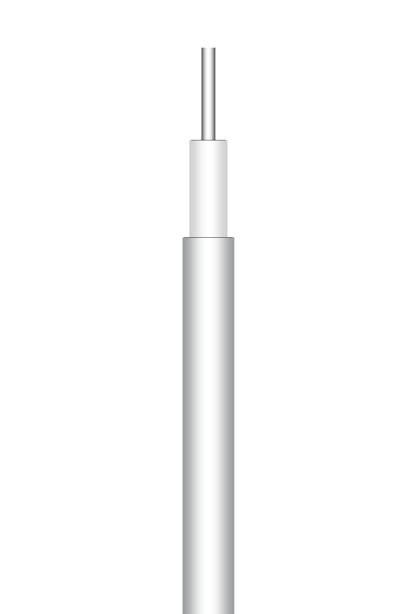
P/N: C291 850 005 (MIL-C-17/133-00007)
APPLICATION NOTE
Due to the outer conductor coating (tin), this cable can be used instead of RG405 for applications requiring high corrosion resistance and improved solderability.
CONSTRUCTION / DIMENSIONS
ELECTRICAL CHARACTERISTICS
Characteristic impedance
MECHANICAL CHARACTERISTICS Recommended
ENVIRONMENTAL CHARACTERISTICS
Semi-rigid cable .085 (Non magnetic)
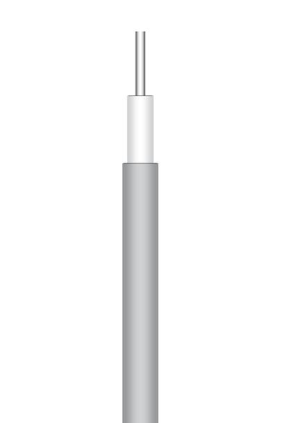
CONSTRUCTION
P/N: C291 851 001 (MIL-C-17/133-00008)
APPLICATION NOTE
Based on RG405 standard, this cable is used where non magnetic is required.
/ DIMENSIONS
ELECTRICAL CHARACTERISTICS
Characteristic impedance
Operating frequency range
Shielding effectiveness
dB Voltage withstanding
MECHANICAL CHARACTERISTICS
ENVIRONMENTAL CHARACTERISTICS Operating
Halogen free No
FREQUENCY / ATTENUATION (typ.) / CW MAX POWER (sea level / 25 °C)
(1) SPCCS = Silver Plated Copper Covered Steel
(2) PTFE = PolyTetraFluoroEthylene
(3) TPC = Tin Plated Copper
Note:
Typical attenuation for a couple of connectors (dB) = 0.045 x √f (GHz)
Attenuation calculation (dB/m) (0.61 x √f GHz) + (0.04 x f GHz)
Power calculation (W) 100 / √f GHz
(1) SPC = Silver Plated Copper (2) PTFE = PolyTetraFluoroEthylene
18-29 Go online for data sheets & assembly instructions. Visit www.radiall.com and enter the part number. SIMPLIFICATION IS OUR INNOVATION
Material mm Inches Center conductor Solid SPCCS(1) 0.51 0.020 Dielectric Solid PTFE(2) 1.68 0.066 Inner shield TPC(3) 2.20 0.087
shield - -Jacket - - -
Outer
50Ω ± 1.5Ω
DC - 20 GHz Shielding
110 dB Voltage
5 000 V DC Peak power 1.9 kW Capacitance 100 pF / m 30 pF / ft Velocity of propagation 70 % (4.8 ns / m)
Operating frequency range
effectiveness
withstanding
minimum bending radius 3.17 mm 0.125 inch Weight 20.0 g / m 0.0135 lbs / ft
Operating temperature range -40 / +125 °C -40 / +257 °F Fire resistance N/A
free No
MAX POWER
GHz dB / m dB / ft Watts 1.0 0.65 0.20 100 2.0 0.94 0.29 71 3.0 1.18 0.36 58 6.0 1.73 0.53 41 8.0 2.05 0.62 35 10.0 2.33 0.71 32 12.4 2.64 0.80 28 18.0 3.31 1.00 24 20.0 3.53 1.07 22 Attenuation calculation (dB/m) (0.61 x √f GHz) + (0.04 x f GHz) Power calculation
100 /
GHz
Halogen
FREQUENCY / ATTENUATION (typ.) / CW
(sea level / 25 °C)
(W)
√f
Material mm Inches Center conductor Solid SPC(1) 0.51 0.020 Dielectric Solid PTFE(2) 1.68 0.066 Inner shield Copper tubing 2.20 0.087
- - -
- - -
Outer shield
Jacket
50Ω ± 1.5Ω
DC -
20 GHz
110
5
100 pF / m 30 pF / ft Velocity of propagation 70 % (4.8 ns / m)
000 V rms Peak power 1.9 kW Capacitance
minimum bending radius 3.17 mm 0.125 inch Weight 20.0 g / m 0.0135 lbs / ft
Recommended
-40 / +125 °C -40 / +257 °F
N/A
temperature range
Fire resistance
GHz dB / m dB / ft Watts 1.0 0.65 0.20 100 2.0 0.94 0.29 71 3.0 1.18 0.36 58 6.0 1.73 0.53 41 8.0 2.05 0.62 35 10.0 2.33 0.71 32 12.4 2.64 0.80 28 18.0 3.31 1.00 24 20.0 3.53 1.07 22
CABLE ASSEMBLIES
CABLE ASSEMBLIES
Semi-rigid cable .085 (Aluminum)
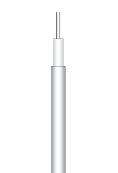
P/N: C291 844 187 (MIL-C-17/133-00013)
APPLICATION NOTE
Based on RG405 standard, this cable will be selected for application requiring easy conformability and/or application requiring reduced weight.
Due to the aluminum outer conductor, this cable can be hand formed with exceptional ease with no spring back effect.
The cable can be reshaped, eliminating the need for costly drawings.
The outer conductor material (aluminum) slightly increases the attenuation compared to standard RG405.
CONSTRUCTION / DIMENSIONS
Hand-formable cable .141 (Unjacketed)
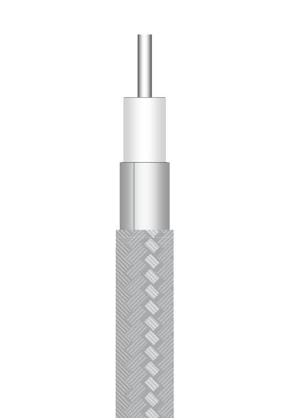
P/N: C291 864 065
APPLICATION NOTE
This handformable cable is an alternative to RG402 for applications requiring an easy routing on equipment.
Due to the outer conductor construction, this cable can be hand formed with exceptional ease with no spring back effect. The cable can be reshaped, eliminating the need for costly drawings.
Attenuation is a little bit higher than RG402 but the temperature range is wider.
CONSTRUCTION / DIMENSIONS
ELECTRICAL CHARACTERISTICS
Characteristic
ELECTRICAL CHARACTERISTICS
MECHANICAL CHARACTERISTICS
ENVIRONMENTAL CHARACTERISTICS
MECHANICAL CHARACTERISTICS
ENVIRONMENTAL CHARACTERISTICS
Operating temperature range -65 / +150 °C -85
Halogen free No
FREQUENCY / ATTENUATION (typ.) / CW MAX POWER (sea level / 25 °C)
(1) SPCCS = Silver Plated Copper Covered Steel
(2) PTFE = PolyTetraFluoroEthylene
(3) TS = Tin Soaked
(4) one time
(5) repeated
Note:
18-30 Go online for data sheets & assembly instructions. Visit www.radiall.com and enter the part number. SIMPLIFICATION IS OUR INNOVATION
Material mm Inches Center conductor Solid SPCCS(1) 0.51 0.020 Dielectric Solid PTFE(2) 1.68 0.066 Inner shield TPAI(2) tubing 2.20 0.087 Outer shield - -Jacket - - -
impedance 50Ω ± 1Ω Operating frequency range DC - 20 GHz Shielding effectiveness 110 dB Voltage withstanding 5 000 V rms Peak power 1.9 kW Capacitance 100 pF / m 30 pF / ft Velocity of propagation 70 % (4.8 ns / m)
Characteristic
Recommended minimum bending radius 1.8 mm 0.07 inch Weight 10.7 g / m 0.0072 lbs / ft
Operating temperature range -40 / +125 °C -40 / +257 °F Fire resistance N/A Halogen free No
CW MAX POWER
level
GHz dB / m dB / ft Watts 1.0 0.68 0.20 100 2.0 0.98 0.30 71 3.0 1.22 0.37 58 6.0 1.80 0.54 41 8.0 2.12 0.64 35 10.0 2.41 0.73 32 12.4 2.73 0.83 28 18.0 3.41 1.03 24 20.0 3.64 1.10 22 Attenuation calculation (dB/m) (0.635 x √f GHz) + (0.04 x f GHz) Power calculation (W) 100 / √f GHz
SPCCS = Silver Plated Copper Covered Steel (2) PTFE = PolyTetraFluoroEthylene
TPAl
Tin Plated Aluminum
FREQUENCY / ATTENUATION (typ.) /
(sea
/ 25 °C)
(1)
(3)
=
Material mm Inches Center conductor Solid SPCCS(1) 0.92 0.036 Dielectric Solid PTFE(2) 2.95 0.116 Inner shield Copper tape -Outer shield TS(3) braid 3.50 0.138 Jacket - - -
Operating
GHz Shielding effectiveness 90 dB Voltage withstanding 5 000 V rms Peak power 3.4 kW Capacitance 97.5 pF / m 29.5 pF / ft Velocity of propagation 70 % (4.8 ns / m)
impedance 50Ω ± 2Ω
frequency range DC - 20
Recommended minimum bending radius 6.4(4) / 19(5) mm 0.25(4) / 0.75(5) inch Weight 33 g / m 0.0221 lbs / ft
/ +302 °F
Fire resistance N/A
GHz dB / m dB / ft Watts 1.0 0.39 0.12 315 2.0 0.57 0.17 223 3.0 0.72 0.22 182 6.0 1.09 0.33 129 8.0 1.30 0.39 111 10.0 1.49 0.45 100 12.4 1.71 0.52 89 18.0 2.18 0.66 74 20.0 2.34 0.71 70 Attenuation calculation (dB/m) (0.345 x √f GHz) + (0.04 x f GHz)
315
√f GHz
Power calculation (W)
/
Typical attenuation for a couple of connectors (dB) = 0.045 x √f (GHz)
Hand-formable cable .141 (Jacketed)
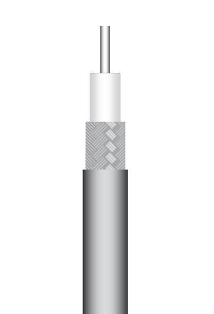
P/N: C291 866 378
APPLICATION NOTE
This jacketed cable will be used instead of standard unjacketed .141 for applications requiring electrical insulation and/or protection against environmental aggressions (chemical, humidity...).
The FEP jacket allows this cable to be used under severe thermal conditions.
The jacket slightly increases the spring back effect.
CONSTRUCTION / DIMENSIONS
ELECTRICAL CHARACTERISTICS Characteristic
Semi-rigid cable .141 (RG402 - KS2)
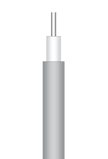
P/N: C291 860 001 (MIL-C-17/130-RG402) (NF-C-93/551-KS2)
RG402 is one of the most popular semi-rigid RG cables.
RG402 will be preferred to flexible RG142 for applications requiring high frequency range, low attenuation, high screening effectiveness, very small bending radius and/or no spring back effect. APPLICATION NOTE
CONSTRUCTION / DIMENSIONS
MECHANICAL CHARACTERISTICS
ENVIRONMENTAL CHARACTERISTICS
Operating temperature range -65 / +150 °C -85 / +302 °F Fire resistance Yes (CSA FT6 / IEC 332-2) Halogen free No
FREQUENCY / ATTENUATION (typ.) / CW MAX POWER (sea level / 25 °C)
ELECTRICAL CHARACTERISTICS
Characteristic
Operating frequency range
Shielding effectiveness
propagation
% (4.8 ns / m)
MECHANICAL CHARACTERISTICS
Recommended
ENVIRONMENTAL CHARACTERISTICS
Operating temperature range -40 / +125 °C -40 / +257 °F
Fire resistance N/A Halogen free No
FREQUENCY / ATTENUATION (typ.) / CW MAX POWER (sea level / 25 °C)
(3) TS = Tin Soaked
(4) FEP = Fluorinated Ethylene Propylene
(5) one time
(6) repeated
Note: Typical attenuation for a couple of connectors (dB) = 0.045 x √f (GHz)
Attenuation calculation (dB/m) (0.30 x √f GHz) + (0.04 x f GHz) Power calculation (W) 315 / √f GHz
(1) SPCCS = Silver Plated Copper Covered Steel (2) PTFE = PolyTetraFluoroEthylene
18-31 Go online for data sheets & assembly instructions. Visit www.radiall.com and enter the part number. SIMPLIFICATION IS OUR INNOVATION
Material mm Inches Center conductor Solid SPC(1) 0.92 0.036 Dielectric Solid PTFE(2) 2.98 0.117 Inner shield TS(3) braid 3.50 0.138 Outer shield - -Jacket Black FEP(4) 4.05 0.159
impedance 50Ω ± 2Ω Operating frequency range DC - 20 GHz Shielding effectiveness 90 dB Voltage withstanding 5 000 V rms Peak power 3.4 kW Capacitance 97.5 pF / m 29.5 pF / ft Velocity of propagation 70 % (4.8 ns / m)
Recommended minimum bending radius 11(5)
33(6) mm 0.43(5)
1.3(6) inch Weight 38 g / m 0.0254 lbs / ft
/
/
GHz dB / m dB / ft Watts 1.0 0.43
2.0 0.63
3.0 0.80 0.24 182 6.0 1.20 0.36 129 8.0 1.42 0.43 111 10.0 1.63 0.49 100 12.4 1.87 0.57 89 18.0 2.37 0.72 74 20.0 2.54 0.77 70 Attenuation calculation (dB/m) (0.390 x √f GHz) + (0.04 x f GHz) Power calculation (W) 315 / √f GHz (1)
Silver Plated Copper (2)
PolyTetraFluoroEthylene
0.13 315
0.19 223
SPC =
PTFE =
Material mm Inches Center
SPCCS(1) 0.92 0.036 Dielectric Solid PTFE(2) 2.98 0.117 Inner shield Copper tubing 3.58 0.141 Outer shield - -Jacket - - -
conductor Solid
impedance 50Ω ± 1Ω
DC
GHz
- 20
110 dB
5 000
Peak
3.4 kW
Voltage withstanding
V rms
power
Capacitance 89 pF / m 27 pF / ft Velocity of
70
minimum bending radius 6.35 mm 0.250 inch Weight 46 g / m 0.0309 lbs / ft
GHz dB / m dB / ft Watts 1.0 0.34 0.10 315 2.0 0.50 0.15 223 3.0 0.64 0.19 182 6.0 0.97 0.30 129 8.0 1.17 0.35 111 10.0 1.35 0.41 100 12.4 1.55 0.47 89 18.0 1.99 0.60 74 20.0 2.14 0.65 70
CABLE ASSEMBLIES
CABLE ASSEMBLIES
Semi-rigid cable .141 (Tinned copper)
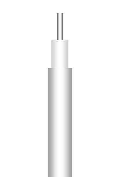
P/N: C291 862 005
(MIL-C-17/130-00005)
Due to the outer conductor coating (tin), this cable will be used instead of RG402 for applications requiring high corrosion resistance and improved solderability. This cable is also an economical alternative to .141 silvered copper. APPLICATION NOTE
CONSTRUCTION / DIMENSIONS
Semi-rigid cable .141 (Silvered copper)
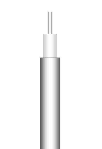
P/N: C291 861 066
APPLICATION NOTE
Based on RG402 standard, this cable is used where non magnetic is required.
In addition, due to the outer conductor coating (silver), this cable will be used instead of RG402 for applications requiring high corrosion resistance and improved solderability.
CONSTRUCTION / DIMENSIONS
ELECTRICAL CHARACTERISTICS
MECHANICAL CHARACTERISTICS
ENVIRONMENTAL CHARACTERISTICS
ELECTRICAL CHARACTERISTICS Characteristic
MECHANICAL
ENVIRONMENTAL CHARACTERISTICS
Operating
Fire resistance N/A
Halogen free No
FREQUENCY / ATTENUATION (typ.) / CW MAX POWER (sea level / 25 °C)
(1) SPCCS = Silver Plated Copper Covered Steel
(2) PTFE = PolyTetraFluoroEthylene (3) TPC = Tin Plated Copper
Note: Typical attenuation for a couple of connectors (dB) = 0.045 x √f (GHz)
Attenuation calculation (dB/m) (0.30 x √f
+ (0.04 x f
Power calculation (W) 315 / √f GHz
(1) SPC = Silver Plated Copper
(2) PTFE = PolyTetraFluoroEthylene
18-32 Go online for data sheets & assembly instructions. Visit www.radiall.com and enter the part number. SIMPLIFICATION IS OUR INNOVATION
Material mm Inches Center conductor Solid SPCCS(1) 0.92 0.036 Dielectric Solid PTFE(2) 2.98 0.117 Inner shield TPC(3) 3.58 0.141 Outer shield - -Jacket - - -
Characteristic impedance 50Ω ± 1Ω Operating frequency range DC - 20 GHz Shielding effectiveness 110 dB Voltage withstanding 5 000 V rms Peak power 3.4 kW Capacitance 89 pF / m 27 pF / ft Velocity of propagation 70 % (4.8 ns / m)
Recommended minimum bending radius 1.90 mm 0.075 inch Weight 46 g / m 0.0309 lbs / ft
Operating temperature range -40 / +125 °C -40 / +257 °F Fire resistance N/A Halogen free No FREQUENCY / ATTENUATION (typ.) / CW MAX POWER (sea level / 25 °C) GHz dB / m dB / ft Watts 1.0 0.34 0.10 315 2.0 0.50 0.15 223 3.0 0.64 0.19 182 6.0 0.97 0.30 129 8.0 1.17 0.35 111 10.0 1.35 0.41 100 12.4 1.55 0.47 89 18.0 1.99 0.60 74 20.0 2.14 0.65 70 Attenuation calculation (dB/m) (0.30 x √f GHz) + (0.04 x f GHz) Power calculation (W) 315 / √f GHz
Material mm Inches Center conductor Solid SPC(1) 0.92 0.036 Dielectric Solid PTFE(2) 2.98 0.117 Inner shield SPC(1) tubing 3.58 0.141 Outer shield - -Jacket - - -
impedance 50Ω ± 1Ω Operating frequency range DC - 20 GHz Shielding effectiveness 110 dB Voltage withstanding 5 000 V rms Peak power 3.4 kW Capacitance 89 pF / m 27 pF / ft Velocity of propagation 70 % (4.8 ns / m)
Recommended minimum bending radius 1.90 mm 0.075 inch Weight 46 g / m 0.0309 lbs / ft
CHARACTERISTICS
temperature
-40 / +125 °C -40 / +257 °F
range
GHz dB / m dB / ft Watts 1.0 0.34 0.10 315 2.0 0.50 0.15 223 3.0 0.64 0.19 182 6.0 0.97 0.30 129 8.0 1.17 0.35 111 10.0 1.35 0.41 100 12.4 1.55 0.47 89 18.0 1.99 0.60 74 20.0 2.14 0.65 70
GHz)
GHz)
Semi-rigid cable .141 (Non magnetic)
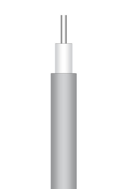
P/N: C291 861 061
APPLICATION NOTE
Based on RG402 standard, this cable is used where non magnetic is required.
CONSTRUCTION / DIMENSIONS
Semi-rigid cable .141 (Aluminum)
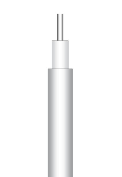
P/N: C291 864 187 (MIL-C-17/130-00009)
APPLICATION NOTE
Based on RG402 standard, this cable will be selected for application requiring easy conformability and/or application requiring reduced weight. Due to the aluminum outer conductor, this cable can be hand formed with exceptional ease with no spring back effect. Cable can be reshaped, eliminating the need for costly drawings. The outer conductor material (aluminum) slightly increases the attenuation compared to standard RG402.
CONSTRUCTION / DIMENSIONS
ELECTRICAL CHARACTERISTICS
Characteristic impedance
Operating frequency range
MECHANICAL CHARACTERISTICS Recommended
ENVIRONMENTAL CHARACTERISTICS
Halogen free No
FREQUENCY / ATTENUATION (typ.) /
(sea level / 25 °C)
PTFE = PolyTetraFluoroEthylene
Note: Typical attenuation for a couple of connectors (dB) = 0.045 x √f (GHz)
ELECTRICAL CHARACTERISTICS
Characteristic impedance 50Ω ± 1Ω
Operating frequency range DC - 20 GHz
Shielding effectiveness 110 dB
Voltage withstanding 5
MECHANICAL CHARACTERISTICS
Recommended
ENVIRONMENTAL CHARACTERISTICS
Operating
FREQUENCY / ATTENUATION (typ.) / CW MAX POWER (sea level / 25 °C)
Attenuation calculation (dB/m) (0.32 x √f GHz) + (0.04 x f GHz)
Power
(W)
18-33 Go online for data sheets & assembly instructions. Visit www.radiall.com and enter the part number. SIMPLIFICATION IS OUR INNOVATION
Material mm Inches Center conductor Solid SPC(1) 0.92 0.036 Dielectric Solid PTFE(2) 2.98 0.117 Inner shield Copper tubing 3.58 0.141
shield - -Jacket - - -
Outer
50Ω ± 1Ω
DC
Voltage
Peak
Capacitance
Velocity
- 20 GHz Shielding effectiveness 110 dB
withstanding 5 000 V rms
power 3.4 kW
89 pF / m 27 pF / ft
of propagation 70 % (4.8 ns / m)
minimum bending radius 2.54 mm 0.100 inch Weight 46 g / m 0.0309 lbs / ft
-40
+125 °C -40 / +257 °F
Operating temperature range
/
Fire resistance N/A
MAX POWER
GHz dB / m dB / ft Watts 1.0 0.34 0.10 315 2.0 0.50
223 3.0 0.64 0.19 182 6.0 0.97 0.30 129 8.0 1.17 0.35 111 10.0 1.35 0.41 100 12.4 1.55 0.47 89 18.0 1.99 0.60 74 20.0 2.14 0.65 70 Attenuation calculation (dB/m) (0.30 x √f GHz) + (0.04 x f GHz) Power calculation (W) 315 / √f GHz (1)
Copper (2)
CW
0.15
SPC = Silver Plated
Material mm Inches Center conductor Solid SPCCS(1) 0.92 0.036 Dielectric Solid PTFE(2) 2.98 0.117 Inner shield TPAl(3) 3.58 0.141
shield - - -
- - -
Outer
Jacket
000 V rms Peak power 3.4 kW Capacitance 89 pF / m 27 pF / ft Velocity of propagation 70 % (4.8 ns / m)
minimum bending radius 3.17 mm 0.125 inch Weight 30 g / m 0.0185 lbs / ft
-40 / +125 °C -40 / +257 °F Fire
temperature range
resistance N/A Halogen free No
GHz dB / m dB / ft Watts 1.0 0.36 0.11 315 2.0 0.53 0.16 223 3.0 0.67 0.20 182 6.0 1.02 0.31 129 8.0 1.23 0.37 111 10.0 1.41 0.43 100 12.4 1.62 0.49 89 18.0 2.08 0.63 74 20.0 2.23 0.68 70
calculation
315 / √f GHz (1) SPCCS = Silver Plated Copper Covered Steel (2) PTFE = PolyTetraFluoroEthylene (3) TPAl = Tin Plated Aluminum
CABLE ASSEMBLIES
CABLE ASSEMBLIES
Semi-rigid cable .250 (RG401 - KS3)
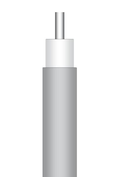
P/N: C291 870 001 (MIL-C-17/129-RG401) (NF-C-93/551-KS3)
APPLICATION NOTE
RG401 will be used for application requiring very low attenuation, high power and high screening effectiveness.
Note: reduced operating temperature range.
CONSTRUCTION / DIMENSIONS
Semi-rigid cable .250 (Aluminum)
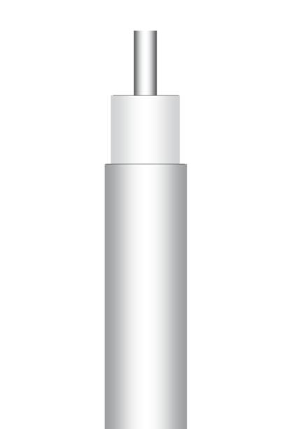
P/N: C291 874 187
APPLICATION NOTE
Based on RG401 standard, this cable will be selected for application requiring easy conformability and/or application requiring reduced weight.
Due to the aluminum outer conductor, this cable can be hand formed with exceptional ease with no spring back effect.
Cable can be reshaped, eliminating the need for costly drawings.
The outer conductor material (aluminum) slightly increases the attenuation compared to standard RG401.
CONSTRUCTION / DIMENSIONS
ELECTRICAL CHARACTERISTICS
MECHANICAL CHARACTERISTICS
ENVIRONMENTAL CHARACTERISTICS
ELECTRICAL CHARACTERISTICS
MECHANICAL CHARACTERISTICS
Halogen free No
FREQUENCY / ATTENUATION (typ.) / CW MAX
(1) SPC = Silver Plated Copper (2) PTFE = PolyTetraFluoroEthylene
Note:
Typical attenuation for a couple of connectors (dB) = 0.045 x
Attenuation calculation
Power calculation (W) 550 / √f GHz
18-34 Go online for data sheets & assembly instructions. Visit www.radiall.com and enter the part number. SIMPLIFICATION IS OUR INNOVATION
Material mm Inches Center conductor Solid SPC(1) 1.63 0.064 Dielectric Solid PTFE(2) 5.31 0.209 Inner shield Copper tubing 6.35 0.250 Outer shield - -Jacket - - -
Characteristic impedance 50Ω ± 0.5Ω Operating frequency range DC - 18 GHz Shielding effectiveness 110 dB Voltage withstanding 7 500 V rms Peak power 6.1 kW Capacitance 89 pF / m 27 pF / ft Velocity of propagation 70 % (4.8 ns / m)
Recommended minimum bending radius 9.53 mm 0.375 inch Weight 140 g / m 0.0945 lbs / ft
Operating temperature range -40 / +90 °C -40 / +194 °F Fire resistance N/A Halogen free No FREQUENCY / ATTENUATION (typ.) / CW MAX POWER (sea level / 25 °C) GHz dB / m dB / ft Watts 1.0 0.21 0.06 900 2.0 0.31 0.09 636 3.0 0.41 0.12 520 6.0 0.64 0.20 367 8.0 0.79 0.24 318 10.0 0.92 0.28 285 12.4 1.08 0.33 256 18.0 1.42 0.43 212 20.0 1.54 0.47 201 Attenuation calculation (dB/m) (0.165 x √f GHz) + (0.04 x f GHz) Power calculation (W) 900 / √f GHz
Material mm Inches Center conductor Solid SPC(1) 1.63 0.064 Dielectric Solid PTFE(2) 5.31 0.209 Inner shield TPAl(3) tubing 6.35 0.250 Outer shield - -Jacket - - -
50Ω ± 1Ω Operating frequency range DC - 18 GHz Shielding effectiveness 110 dB Voltage withstanding 7 500 V rms Peak power 6.1 kW Capacitance 89 pF / m 27 pF / ft Velocity of propagation 70 % (4.8 ns / m)
Characteristic impedance
Recommended minimum bending radius 9.53 mm 0.375 inch Weight 79.5 g / m 0.0530 lbs / ft
Operating temperature range -40 / +100 °C -40 / +212 °F
ENVIRONMENTAL CHARACTERISTICS
Fire resistance N/A
POWER
level
GHz dB / m dB / ft Watts 1.0 0.22 0.07 550 2.0 0.33 0.10 389 3.0 0.43 0.13 318 6.0 0.68 0.21 225 8.0 0.83 0.25 194 10.0 0.97 0.29 174 12.4 1.13 0.34 156 18.0 1.48 0.45 130 20.0 1.60 0.49 123
(sea
/ 25 °C)
GHz)
(dB/m) (0.18 x √f GHz) + (0.04 x f
(1) SPC = Silver Plated Copper (2) PTFE = PolyTetraFluoroEthylene (3) TPAl = Tin Plated Aluminum
GHz)
√f (
Low loss flexible cable 2.6/50 S+F (AEP-100FR alternative to LMR-100FR®)
REGULATIONS
RoHS compliant UL/NEC: CMR UL/CSA: FT4
P/N: C291 327 060
APPLICATION NOTE
AEP-100FR cable is an alternative solution to 50 Ohms LMR-100FR® cable offering the same performance and similar construction with cost advantage.
CONSTRUCTION / DIMENSIONS
ELECTRICAL CHARACTERISTICS
Characteristic impedance
Operating
CONNECTORS COMPATIBLE WITH AEP-100FR (and to LMR® 100FR)
QMA Series
P/N Interface Model
R123 071 000 Straight plug Crimp type
SMA Series
P/N Interface Model
R124 071 123 Straight plug Crimp type
R124 172 123 R/A plug Crimp type
R124 312 123 Straight BH jack Crimp type
TNC Series
R143 075 000 Straight plug Crimp type
N Series
P/N Interface Model
R161 072 000 Straight plug Crimp type
(1) BC = Bare Copper
(2) PE = PolyEthylene
Phase
MECHANICAL CHARACTERISTICS Maximum weight
CABLE ASSEMBLIES
ENVIRONMENTAL CHARACTERISTICS
FREQUENCY / ATTENUATION (typ.) / AVG POWER (*)
(*) = Avg power calculated at sea level / 40°C and VSWR 1:0 (Cable-assembly power ratings may be limited by the connector type. Please contact us for specific needs)
18-35 Go online for data sheets & assembly instructions. Visit www.radiall.com and enter the part number. SIMPLIFICATION IS OUR INNOVATION
P/N
Interface Model
Material mm Inches Center conductor Solid BC (1) 0.46 0.018 Dielectric Solid PE(2) 1.52 0.06 Inner shield Al Tape Unbonded 1.65 0.065 Outer shield Tinned Copper braid 2.11 0.083 Outer jacket Black LSZH 2.79 0.11
50 ohms
frequency range DC - 6 GHz
constant 2.3
> 90 dB
66 % Capacitance 101.1 pF / m 30.8 pF / ft Inductance 0.25 uH / m 0.077 uH / ft Time delay 5.05 nS / m 1.54 nS / ft Inner conductor DC resistance 266 ohms / km 81.0 ohms / 1000 ft Outer conductor DC resistance 31.2 ohms / km 9.5 ohms / 1000 ft Voltage
500
DC
Dielectric
Screening effectiveness
Velocity of propagation
withstand
Volts
Jacket spark 2000 Volts RMS Peak power 0.6kW
stability over temp < 25 ppm / deg C
14 g
m 0.092 lb / ft
6.4
0.25 inch
mm 1.0 inch Bending moment 0.014 N-m 0.1 ft-lb Tensile strength 6.8 kg 15 lb Flat plate crush 0.18 kg / mm 10 lb / inch
/
Min. bend radius: installation
mm
Min. bend radius: repeated 25.4
Installation temperature range -40 / +85 °C -40 / +185 °F Storage temperature range -70 / +85 °C -94 / +185 °F Operating temperature range -40 / +85 °C -40 / +185 °F
MHz DB / 100 m DB / 100 ft kW 30 12.9 3.9 0.230 50 16.7 5.1 0.180 150 29.4 8.9 0.100 220 35.8 10.9 0.083 450 51.9 15.8 0.057 900 74.9 22.8 0.039 1500 98.7 30.1 0.029 1800 109.0 33.2 0.027 2000 115.5 35.2 0.025 2500 130.6 39.8 0.022 5800 210.3 64.1 0.013
CABLE ASSEMBLIES
Flexible low loss cable 5/50 S+F (AEP-195FR alternative to LMR-195FR®)
REGULATIONS
RoHS compliant UL/NEC:CMR UL/CSA: FT4
P/N: C291 327 010
APPLICATION NOTE
AEP-195FR cable is an alternative solution to 50 Ohms LMR-195FR® cable offering the same performance and similar construction with cost advantage.
CONSTRUCTION / DIMENSIONS
ELECTRICAL CHARACTERISTICS Characteristic
CONNECTORS COMPATIBLE WITH AEP-195FR (and to LMR® 195FR)
QMA Series
P/N Interface Model
R123 075 200 Straight plug Crimp type
SMA Series
P/N Interface Model
R124 075 210 Straight plug Crimp type
R124 175 110 R/A plug Crimp type
TNC Series
P/N Interface Model
R143 082 027 Straight plug Crimp type
N Series
P/N Interface Model
R161 082 120 Straight plug Crimp type
(1) BC = Bare Copper
(2) PE = PolyEthylene
MECHANICAL CHARACTERISTICS
ENVIRONMENTAL CHARACTERISTICS
FREQUENCY / ATTENUATION (typ.) / AVG POWER (*)
= Avg
(Cable-assembly power ratings may be limited by the connector type. Please contact us for specific needs)
18-36 Go online for data sheets & assembly instructions. Visit www.radiall.com and enter the part number. SIMPLIFICATION IS OUR INNOVATION
Material mm Inches Center conductor Solid BC (1) 0.94 0.037 Dielectric Foam PE(2) 2.79 0.11 Inner shield Aluminum Tape 2.95 0.116 Outer shield Tinned Copper braid 3.53 0.139 Outer jacket Black LSZH 4.95 0.195
impedance 50 ohms Operating frequency range DC - 6 GHz Dielectric constant 1.56 Screening effectiveness > 90 dB Velocity of propagation 76 % Capacitance 83.3 pF / m 25.4 pF / ft Inductance 0.21 uH / m 0.064 uH / ft Time delay 4.17 nS / m 1.27 nS / ft Inner conductor DC resistance 24.9 ohms / km 7.6 ohms / 1000 ft Outer conductor DC resistance 16.1 ohms / km 4.9 ohms / 1000 ft Voltage withstand 1000 Volts DC Jacket spark 3000 Volts RMS Peak power 2.5kW
stability over temp < 25 ppm / deg C
Phase
Maximum weight 30 g / m 0.021 lb / ft Min. bend radius: installation 12.7 mm 0.5 inch Min. bend radius: repeated 50.8 mm 2.0 inch Bending moment 0.27 N-m 0.2 ft-lb Tensile strength 18.2 kg 40 lb Flat plate crush 0.27 kg / mm 15 lb / inch
Installation temperature range -40 / +85 °C -40 / +185 °F Storage temperature range -70 / +85 °C -94 / +185 °F Operating temperature range -40 / +85 °C -40 / +185 °F
MHz DB / 100 m DB / 100 ft kW 30 6.5 2.0 0.89 50 8.4 2.5 0.68 150 14.6 4.4 0.39 220 17.7 5.4 0.32 450 25.5 7.8 0.22 900 36.5 11.1 0.16 1500 47.7 14.5 0.12 1800 52.5 16.0 0.11 2000 55.4 16.9 0.10 2500 62.4 19.0 0.09 5800 98.1 29.9 0.06
40°C
VSWR
(*)
power calculated at sea level /
and
1:0
Low loss Flexible cable 5/50 S+F (AEP-200FR alternative to LMR-200FR®)
REGULATIONS
RoHS compliant UL/NEC: CMR UL/CSA: FT4
APPLICATION NOTE P/N: C291 327 020
AEP-200FR cable is an alternative solution to 50 Ohms LMR-200FR® cable offering the same performance and similar construction with cost advantage.
CONNECTORS COMPATIBLE WITH AEP-200FR (and to LMR® 200FR)
QMA Series
P/N Interface Model R123 096 110 Straight plug Crimp type
SMA Series
P/N Interface Model R124 076 450 Straight plug Crimp type R124 175 200 R/A plug Crimp type
TNC Series
P/N Interface Model
R143 082 200 Straight plug Crimp type
N Series
P/N Interface Model
R161 082 200 Straight plug Crimp type
R161 182 080 R/A plug Crimp type
R161 329 130 Straight BH jack Crimp type
CONSTRUCTION / DIMENSIONS
ELECTRICAL CHARACTERISTICS
Characteristic impedance 50 ohms
Operating frequency range DC - 6 GHz
Dielectric constant 1.45
Screening effectiveness > 90 dB
Velocity of propagation 83 %
Capacitance 80.3 pF / m 24.5 pF / ft Inductance 0.20 uH / m 0.061 uH / ft Time delay 4.02 nS / m 1.22 nS / ft
Inner
Voltage withstand 1000 Volts DC
Jacket spark 3000 Volts RMS
Peak power 2.5kW
Phase stability over temp < 25 ppm / deg C
MECHANICAL CHARACTERISTICS
Maximum weight 30 g / m 0.022
CABLE ASSEMBLIES
ENVIRONMENTAL CHARACTERISTICS Installation
FREQUENCY / ATTENUATION
=
(Cable-assemblypower ratings may be limited by the connector
Please contact us for specific needs)
18-37 Go online for data sheets & assembly instructions. Visit www.radiall.com and enter the part number. SIMPLIFICATION IS OUR INNOVATION
Material mm Inches Center conductor Solid BC (1) 1.12 0.044 Dielectric Foam PE(2) 2.95 0.116 Inner shield Aluminum Tape 3.07 0.121 Outer shield Tinned Copper braid 3.66 0.144 Outer jacket Black LSZH 4.95 0.195
conductor DC resistance 17.6 ohms / km 5.36 ohms / 1000 ft
Outer conductor DC resistance 16.1 ohms / km 4.9 ohms / 1000 ft
lb / ft
12.7 mm 0.5 inch Min.
repeated 50.8 mm 2.0 inch
0.2
kg 40 lb
/ mm 15 lb / inch
Min. bend radius: installation
bend radius:
Bending moment 0.27 N-m
ft-lb Tensile strength 18.2
Flat plate crush 0.27 kg
-40
°C -40 / +185 °F
/ +185 °F
temperature range
/ +85
Storage temperature range -70 / +85 °C -94 / +185 °F Operating temperature range -40 / +85 °C -40
(typ.) /
MHz DB / 100 m DB / 100 ft kW 30 5.8 1.8 1.02 50 7.5 2.3 0.79 150 13.1 4.0 0.45 220 15.9 4.8 0.37 450 22.8 7.0 0.26 900 32.6 9.9 0.18 1500 42.4 12.9 0.14 1800 46.6 14.2 0.13 2000 49.3 15.0 0.12 2500 55.4 16.9 0.11 5800 86.5 26.4 0.07
AVG POWER (*)
sea level
40°C and VSWR 1:0
(*)
Avg power calculated at
/
type.
CABLE ASSEMBLIES
Flexible low loss cable 6.1/50 S+F (AEP-240FR alternative to LMR-240FR®)
REGULATIONS
RoHS compliant UL/NEC: CMR UL/CSA: FT4
P/N: C291 327 030
APPLICATION NOTE
AEP-240FR cable is an alternative solution to 50 Ohms LMR-240FR® cable offering the same performance and similar construction with cost advantage.
CONNECTORS COMPATIBLE WITH AEP-240FR (and to LMR® 240FR)
QMA Series
P/N Interface Model
R123 076 310 Straight plug Crimp type
R123 177 100 R/a plug Crimp type
R123 314 010 Straight bh jack Crimp type
R123W 076 310 Wp straight plug Crimp type
R123W 177 110 Wp r/a plug Crimp type
SMA Series
P/N
Interface Model
R124 076 430 Straight plug Crimp type
R124 175 310 R/A plug Crimp type
TNC Series
P/N
Interface Model
R143 084 161 Straight plug Crimp type
N Series
P/N Interface Model
R161 075 030 Straight plug Crimp type
R161 183 310 R/A plug Crimp type
R161 329 140 Straight bh jack Crimp type
QN Series
P/N Interface Model
R164 075 010 Straight plug Crimp type
7/16 Series
P/N Interface Model
R185 085 007 Straight plug Crimp type
R185 320 020 Straight BH jack Crimp type
(1) BC = Bare Copper
(2) PE = PolyEt hylene
CONSTRUCTION / DIMENSIONS
ELECTRICAL CHARACTERISTICS Characteristic
Phase
MECHANICAL CHARACTERISTICS
ENVIRONMENTAL CHARACTERISTICS
FREQUENCY / ATTENUATION (typ.) / AVG POWER (*)
18-38 Go online for data sheets & assembly instructions. Visit www.radiall.com and enter the part number. SIMPLIFICATION IS OUR INNOVATION
Material mm Inches Center conductor Solid BC (1) 1.42 0.056 Dielectric Foam PE(2) 3.81 0.15 Inner shield Aluminum Tape 3.94 0.155 Outer shield Tinned Copper braid 4.52 0.178 Outer jacket Black LSZH 6.1 0.24
impedance 50 ohms Operating frequency range DC - 6 GHz Dielectric constant 1.42
effectiveness > 90 dB Velocity of propagation 84 % Capacitance 79.4 pF / m 24.2 pF / ft Inductance 0.20 uH / m 0.060 uH / ft Time delay 3.97 nS / m 1.21 nS / ft Inner conductor dc resistance 10.5 ohms / km 3.2 ohms / 1000 ft Outer conductor dc resistance 12.8 ohms / km 3.89 ohms / 1000 ft Voltage withstand
Jacket spark
power 5.6kW
Screening
1500 Volts DC
5000 Volts RMS Peak
stability
temp < 25 ppm / deg C
over
Maximum weight 0.05 kg / m 0.034 lb / ft Min. bend radius: installation 19.1 mm 0.75 inch Min. bend radius: repeated 63.5 mm 2.5 inch Bending moment 0.34 N-m 0.25 ft-lb Tensile strength 36.3 kg 80 lb Flat plate crush 0.36 kg / mm 20 lb / inch
Installation temperature range -40 / +85 °C -40 / +185 °F Storage temperature range -70 / +85 °C -94 / +185 °F Operating temperature range -40 / +85 °C -40 / +185 °F
MHz DB / 100 m DB / 100 ft kW 30 4.4 1.3 1.49 50 5.7 1.7 1.15 150 9.9 3.0 0.66 220 12.0 3.7 0.54 450 17.3 5.3 0.38 900 24.8 7.6 0.26 1500 32.4 9.9 0.20 1800 35.6 10.9 0.18 2000 37.7 11.5 0.17 2500 42.4 12.9 0.15 5800 66.8 20.4 0.10 (*)
at sea level / 40°C and VSWR 1:0 (Cable-assembly power ratings may be limited by the connector type.
contact us
specific needs)
= Avg power calculated
Please
for
Low loss Flexible cable 10.3/50 S+F (AEP-400FR alternative to LMR-400FR®)
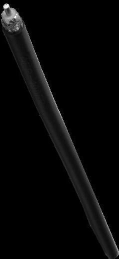
REGULATIONS
RoHS compliant UL/NEC: CMR
UL/CSA: FT4
P/N: C291 .327 040
APPLICATION NOTE
AEP-400FR cable is an alternative solution to 50 Ohms LMR-400FR® cable offering the same performance and similar construction with cost advantage.
CONNECTORS COMPATIBLE WITH AEP-400FR (and to LMR® 400FR)
SMA Series
P/N Interface Model
R124 080 030 Straight plug Crimp type
TNC Series
P/N Interface Model
R143 089 117 Straight plug Crimp type
N Series
P/N Interface Model
R161 088 180 Straight plug Crimp type
R161 184 080 R/A plug Crimp type
R161 331 060 Straight bh jack Crimp type
QN Series
P/N Interface Model
R164 080 020 Straight plug Crimp type
R164 185 007 R/A plug Crimp type
R164 241 020 Straight bh jack Crimp type
7/16 Series
P/N Interface Model
R185 085 007 Straight plug Crimp type
R185 320 020 Straight BH jack Crimp type
(1) BC = Bare Copper
(2) PE = PolyEt hylene
CONSTRUCTION
/ DIMENSIONS
ELECTRICAL CHARACTERISTICS
Characteristic impedance 50 ohms Cut-off frequency 16 GHz
Dielectric constant 1.38
Screening effectiveness > 90 dB
Velocity of propagation 85 %
Capacitance 78.4 pF / m 23.9 pF / ft Inductance 0.20 uH / m 0.060 uH / ft Time delay 3.97 nS / m 1.21 nS / ft
Inner
Outer conductor DC resistance 5.4 ohms / km 1.65 ohms / 1000 ft
Voltage withstand 2500 Volts DC
Jacket spark 8000 Volts RMS
Peak power 16kW
Phase stability over temp < 25 ppm / deg C
MECHANICAL CHARACTERISTICS
Maximum weight 0.10 kg / m 0.068
ENVIRONMENTAL CHARACTERISTICS
FREQUENCY / ATTENUATION (typ.) / AVG POWER (*)
(Cable-assembly power ratings may be limited by
Please contact us for specific needs)
connector
18-39 Go online for data sheets & assembly instructions. Visit www.radiall.com and enter the part number. SIMPLIFICATION IS OUR INNOVATION
Material mm Inches Center conductor Solid BCCAl (1) 2.74 0.108 Dielectric Foam PE(2) 7.24 0.285 Inner shield Aluminum Tape 7.39 0.291 Outer shield Tinned Copper braid 8.13 0.32 Outer jacket Black LSZH 10.29 0.405
conductor DC resistance 4.6 ohms / km 1.39 ohms / 1000 ft
lb / ft
radius: installation 25.4 mm 1.00 inch Min.
repeated 101.6 mm 4.0 inch Bending
0.68
0.5 ft-lb Tensile
72.6 kg 160 lb
kg / mm 40 lb / inch
Min. bend
bend radius:
moment
N-m
strength
Flat plate crush 0.71
Installation temperature range -40 / +85 °C -40 / +185 °F Storage temperature range -70 / +85 °C -94 / +185 °F Operating temperature range -40
-40 / +185 °F
/ +85 °C
MHz DB / 100 m DB / 100 ft kW 30 2.2 0.7 3.33 50 2.9 0.9 2.57 150 5.0 1.5 1.47 220 6.1 1.9 1.20 450 8.9 2.7 0.83 900 12.8 3.9 0.58 1500 16.8 5.1 0.44 1800 18.6 5.7 0.40 2000 19.6 6.0 0.37 2500 22.2 6.8 0.33 5800 35.5 10.8 0.21
power calculated at sea level / 40°C and VSWR 1:0
(*) = Avg
the
type.
CABLE ASSEMBLIES
CABLE ASSEMBLIES
Flexible low loss cable 15/50 S+F (AEP-600FR alternative to LMR-600FR®)
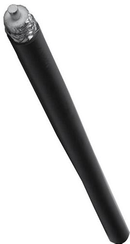
REGULATIONS
RoHS compliant UL/NEC: CMR UL/CSA: FT4
P/N: C291 327 050
APPLICATION NOTE
AEP-600FR cable is an alternative solution to 50 Ohms LMR-600FR® cable offering the same performance and similar construction with cost advantage.
CONSTRUCTION / DIMENSIONS
ELECTRICAL CHARACTERISTICS Characteristic
CONNECTORS COMPATIBLE WITH AEP-600FR (and to LMR® 600FR)
N Series
P/N Interface Model
R161 079 200 Straight plug Crimp type
R161 188 200 R/A plug Crimp type
R161 331 400 Straight BH jack Crimp type
QN Series
P/N Interface Model
R164 080 030 Straight plug Crimp type
7/16 Series
P/N Interface Model
R185 077 010 Straight plug Crimp type
(1) BCCAl = Copper Clad Aluminum
(2) PE = PolyEthylene
Phase
MECHANICAL CHARACTERISTICS
ENVIRONMENTAL CHARACTERISTICS
FREQUENCY / ATTENUATION (typ.) / AVG POWER (*)
(Cable-assembly power ratings may be limited by the connector type. Please contact us for specific needs)
18-40 Go online for data sheets & assembly instructions. Visit www.radiall.com and enter the part number. SIMPLIFICATION IS OUR INNOVATION
Material mm Inches Center conductor Solid BCCAl (1) 4.47 0.176 Dielectric Foam PE(2) 11.56 0.455 Inner shield Aluminum Tape 11.71 0.461 Outer shield Tinned Copper braid 12.45 0.49 Outer jacket Black LSZH 14.99 0.59
impedance 50 ohms Operating frequency range DC - 6 GHz Dielectric constant 1.32
effectiveness > 90 dB Velocity of propagation 87 % Capacitance 76.6 pF / m 23.4 pF / ft Inductance 0.19 uH / m 0.058 uH / ft Time delay 3.83 nS / m 1.17 nS / ft Inner conductor DC resistance 1.7 ohms / km 0.53 ohms / 1000 ft Outer conductor DC resistance 3.9 ohms / km 1.2 ohms / 1000 ft Voltage withstand 4000 Volts DC Jacket spark 8000 Volts RMS
power 40kW
Screening
Peak
stability over temp < 25 ppm / deg C
Maximum weight 0.20 kg / m 0.131 lb / ft Min. bend radius: installation 38.1 mm 1.50 inch Min. bend radius: repeated 152.4 mm 6.0 inch Bending moment 3.73 N-m 2.75 ft-lb Tensile strength 158.9 kg 350 lb Flat plate crush 1.07 kg / mm 60 lb / inch
Installation temperature range -40 / +85 °C -40 / +185 °F Storage temperature range -70 / +85 °C -94 / +185 °F Operating temperature range -40 / +85 °C -40 / +185 °F
MHz DB / 100 m DB / 100 ft kW 30 1.4 0.4 5.51 50 1.8 0.5 4.24 150 3.2 1.0 2.41 220 3.9 1.2 1.97 450 5.6 1.7 1.35 900 8.2 2.5 0.93 1500 10.9 3.3 0.70 1800 12.1 3.7 0.63 2000 12.8 3.9 0.59 2500 14.5 4.4 0.52 5800 23.8 7.3 0.32
40°C
VSWR
(*) = Avg power calculated at sea level /
and
1:0
Connectors
The unique design of SHF cables allows for the use of custom-designed connectors. At Radiall, we pay particular attention to the design and to termination techniques to ensure low VSWR and superior cable performance.
Our cable /connector terminations are designed to maintain shield integrity into the lowest leakage attainable in a flexible assembly. All electrical connections (center contact and inner tape shield) are soldered.
Most popular connector interfaces to fit SHF cable are SMPM, SMP, SSMA, SMA, QRE, TNC, and N Type.
SHF Cable Range
Ultra low loss flexible cable
PFA or FEP jacket
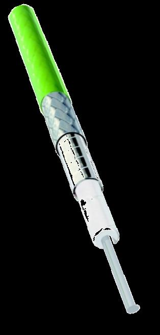
SPC(1) braid
SPC(1) tape
ePTFE tape
Solid SPC(1)
Typical construction
(1) SPC: Silver Plated Copper
(2) Triple shield structure
18-41 Go online for data sheets & assembly instructions. Visit www.radiall.com and enter the part number. SIMPLIFICATION IS OUR INNOVATION
SHF CABLE
Cable VP Max Dia. Attenuation Bending radius Weight SHF2.4M 76% 2.45mm 4.59 dB/m @ 40GHz 10mm 20 g/m DC-40GHz 0.095in 139 dB/100ft 0.394in 6.1 g/ft SHF2.9M (2) 75% 2.90mm 5.92 dB/m @ 67GHz 25mm 23 g/m DC-67GHz 0.114in 179 dB/100ft 0.984in 7.01 g/ft SHF3M 76% 3.64mm 2.76 dB/m @ 40GHz 12.5mm 35 g/m DC-40GHz 0.139in 84 dB/100ft 0.492in 10.6 g/ft SHF4M (2) 84% 4.15mm 2.05 dM/m @ 40GHz 20mm 40 g/m DC-40GHz 0.160in 62 dB/100ft 0.788in 12.2 g/ft SHF4.2M 76% 4.20mm 1.96 dB/m @ 26.5GHz 25mm 45 g/m DC-26.5GHz 0.165in 60 dB/100ft 0.984in 13.6 g/ft SHF4.6M 84% 4.65mm 1.69 dB/m @ 32GHz 25mm 41 g/m DC-32GHz 0.183in 51 dB/100ft 0.984in 12.5 g/ft SHF5M 84% 5.20mm 1.27 dB/m @ 26.5GHz 25mm 60 g/m DC-26.5GHz 0.201in 39 dB/100ft 0.984 18.2 g/ft SHF8M 84% 7.78mm 0.68 dB/m @ 18GHz 40mm 130 g/m DC-18GHz 0.302in 21 dB/100ft 1.575in 39.4 g/ft SHF13 85% 13.80mm 0.33 dB/m @ 9.5GHz 60mm 280 g/m DC-9.5GHz 0.543in 9 dB/100ft 2.362in 84.8 g/ft
SHF CABLE

- 40GHz
DC - 40GHz
SHF2.9M 75%
3.64mm 0.139in.
DC - 67GHz
SIMPLIFICATION IS OUR INNOVATION
SHF3M 76%
DC - 40GHz SPC tape
SHF4.2M
SHF4M 84%
DC - 40GHz
Stranded Inner Conductor Cable
SHF4.2M 76%
SHF4.6M 84% DC - 32GHz
ePTFE tape DC - 26.5GHz
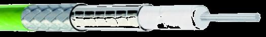
SHF4.6M 84% DC - 32GHz
(*) SPC: Silver Plated Copper Stranded inner conductor cable
Ultra Flexible Cable
Stranded inner conductor cable
DC - 9.5GHz
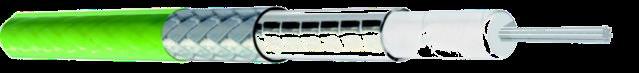
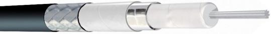
Ultra Flexible cable
Stranded inner conductor cable
SHF13 85%
Heavy Duty Protective Jacket
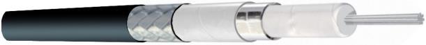
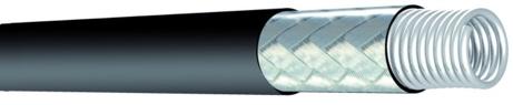
Heavy Duty protective jacket
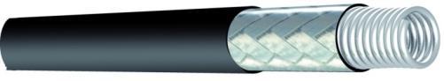
Other version available
A/10 Armored Cable
• A/10 Armored cable

• A/10 Armored cable
4.15mm 0.160in.
4.20mm 0.165in.
0.160in.
4.65mm 0.183in.
4.20mm 0.165in.
5.20mm 0.201in.
4.65mm 0.183in.
4.20mm 0.165in. 4.65mm 0.183in. 5.20mm 0.201in. 7.78mm 0.302in. 13.80mm 0.543in.
7.78mm 0.302in.
5.20mm 0.201in.
13.80mm 0.543in.
7.78mm 0.302in.
1.69 dB/m @32GHz 51 dB/100ft
1.96 dB/m @26.5GHz 60 dB/100ft
dB/m @26.5GHz 60 dB/100ft 1.69 dB/m @32GHz 51 dB/100ft 1,27 dB/m @26.5GHz 39 dB/100ft 0,68 dB/m @18GHz 21 dB/100ft 0,33 dB/m @9.5GHz 9 dB/100ft
1,27 dB/m @26.5GHz 39 dB/100ft
Using stranded center conductor allow better flexibility while keeping good IL performance level.
0,68 dB/m @18GHz 21 dB/100ft
0,33 dB/m @9.5GHz 9 dB/100ft
0,68 dB/m @18GHz 21 dB/100ft
Using standed center conductor allow better flexibility while keeping good IL performance level
0,33 dB/m @9.5GHz 9 dB/100ft
13.80mm 0.543in. 1.96 dB/m @26.5GHz 60 dB/100ft 1.69 dB/m @32GHz 51 dB/100ft 1,27 dB/m @26.5GHz 39 dB/100ft
Unique design of center conductor as well as braiding and jacketing provide a unique flexibility behavior to SHF UF.
Using standed center conductor allow better flexibility while keeping good IL performance level
Unique design of center conductor as well as braiding and jacketing provide a unique flexibility behavior to SHF UF
Using standed center conductor allow better flexibility while keeping good IL performance level
Unique design of center conductor as well as braiding and jacketing provide a unique flexibility behavior to SHF UF
Longer flex life
SHF3, SHF5, SHF8
More flexible
Low bending moment
SHF3, SHF5, SHF8
Up to 1 million flexures
SHF2.2UF, SHF3UF, SHF5UF
More flexible
SHF3, SHF5, SHF8
Low bending moment Up to 1 million flexures
More flexible
SHF2.2UF, SHF3UF, SHF5UF
Projack provides the highest mechanical protection to SHF cables. Despite this high protection level, Projack maintains the same level of flexibility as the original cable.
Projack provides the highest mechanical protection to SHF cables. Despite of this high protection level, Projack maintains the same level of flexibility than the original cable.
Unique design of center conductor as well as braiding and jacketing provide a unique flexibility behavior to SHF UF
Projack provides the highest mechanical protection to SHF cables. Despite of this high protection level, Projack maintains the same level of flexibility than the original cable.
In many customer applicatioons mechanical stress may damage cable assemblies. Radiall has designed several levels of armored structures embedding SHF core lines.
Projack provides the highest mechanical protection to SHF cables. Despite of this high protection level, Projack maintains the same level of flexibility than the original cable.

OD Outdoor Cable
In many customer applicatioons mechanical stress may damage cable assemblies. Radiall has designed several levels of armored structures embedding SHF core lines.
Crush resistant 2500N/10cm
SHF3, SHF5, SHF8
Low bending moment Up to 1 million flexures
UV resistant
Watertightness
SHF2.2UF, SHF3UF, SHF5UF
Crush resistant 2500N/10cm UV resistant Watertightness
Low bending moment Up to 1 million flexures
SHF2.2UF, SHF3UF, SHF5UF
Crush resistant 2500N/10cm UV resistant Watertightness
In many customer applications, mechanical stress may damage cable assemblies. Radiall has designed several levels of armored structures embedding SHF core lines.
Crush resistant 1000N/10cm
Abrasion resistant
Crush resistant 1000N/10cm
SHF5MA/10, SHF8MA/10
Crush resistant 2500N/10cm UV resistant Watertightness
Abrasion resistant
SHF5MA/10, SHF8MA/10
Crush resistant 1000N/10cm
Abrasion resistant
SHF5MA/10, SHF8MA/10
• OD Outdoor cable UV resistant Watertightness
Designed to be used in outdoor environments, Radiall's OutDoor cables are typically chosen for Ground Radars and Navy systems.
SHF5OD, SHF5MOD
Crush resistant 1000N/10cm
• LW-2 Light weight cable
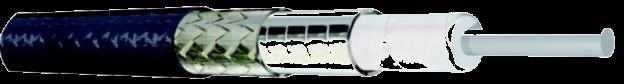
LW-2 Light weight cable
• AF-2 Air Frame cable
In many customer applicatioons mechanical stress may damage cable assemblies. Radiall has designed several levels of armored structures embedding SHF core lines.
Designed to be used in outdoor environments, Radiall's OutDoor cables are typically chosen for Ground Radars and Navy systems.
SHF8OD, SHF8MOD
Abrasion resistant
SHF5MA/10, SHF8MA/10
• OD Outdoor cable UV resistant Watertightness
Radiall's LightWeight range is the best choice for on-board equipements, where weight and density are critical.
Designed for outdoor environments, Radiall's outdoor cables are typically used for Ground Radars and Navy systems.
Designed to be used in outdoor environments, Radiall's OutDoor cables are typically chosen for Ground Radars and Navy systems.
UV resistant
30% weight saving
Watertightness
SHF5MLW-2, SHF8MLW-2
SHF5OD, SHF5MOD
SHF5OD, SHF5MOD SHF8OD, SHF8MOD
SHF8OD, SHF8MOD
UV resistant Watertightness
SHF5OD, SHF5MOD
30% weight saving
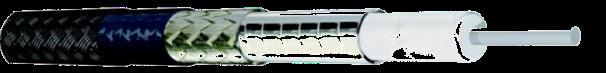
Radiall's LightWeight range is the best choice for on-board equipements, where weight and density are critical.
SHF5MLW-2, SHF8MLW-2
LW-2 Light Weight Cable
SHF8OD, SHF8MOD •
• AF-2 Air Frame cable
• AF-2 Air Frame cable
AF-2 Air Frame Cable
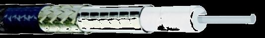
SHF AirFrame cables moto is: Robustness for long life in extreme condition. Radiall's AirFrame cables are used in non-pressurized or notprotected areas.
Radiall's LightWeight range is the best choice for on-board equipements, where weight and density are critical.
Radiall's Lightweight range is the best choice for on-board equipment, where weight and density are critical.
SHF AirFrame cables moto is: Robustness for long life in extreme condition. Radiall's AirFrame cables are used in non-pressurized or notprotected areas.

SHF AirFrame cables moto is: Robustness for long life in extreme condition. Radiall's AirFrame cables are used in non-pressurized or notprotected areas.
SHF AirFrame cables: Robustness for extended life in extreme condition. Radiall's AirFrame cables are used in non-pressurized or notprotected areas.
Hermetically sealed 15 Km (50,000 ft) - 150°C Fluid resistant
30% weight saving
SHF5MAF-2, SHF8MAF-2
30% weight saving
SHF5MLW-2, SHF8MLW-2
SHF5MLW-2, SHF8MLW-2
Hermetically sealed 15 Km (50,000 ft) - 150°C
Fluid resistant
SHF5MAF-2, SHF8MAF-2
Hermetically sealed 15 Km (50,000
Fluid resistant
SHF5MAF-2,
Hermetically sealed
Visit www.radiall.com
15 Km (50,000 ft) - 150°C
Fluid resistant
SHF5MAF-2, SHF8MAF-2
18-42 Go online for data sheets & assembly instructions. Visit www.radiall.com and enter the part number.
PFA or FEP jacket
SPC
Solid SPC (*) SHF5M 84% DC - 26.5GHz SHF8M 84% 85% DC
9.5GHz
-
Ultra Flexible cable
ft)
150°C
-
SHF 23 g/m 7.01 g/ft
SHF8MAF-2
60 mm 2.362 in. 2.05 dB/m @40GHz 62 dB/100ft 139 dB/100ft 20 mm 0.788 in. 25 mm 0.984 in. 25 mm 0.984 in. 25 mm 0.984 in. 40 mm 1.575 in. 4.3 g/ft 35 g/m 10.6 g/ft 2.76 dB/m @40GHz 84 dB/100ft 280 g/m 84.8 g/ft 130 g/m 39.4g/ft 40 g/m 12.2 g/ft 45 g/m 13.6 g/ft 41 g/m 12.5 g/ft 60 g/m 18.2 g/ft 0.394 in. 12.5 mm 0.492 in. 0.095in. 3.64mm
4.15mm
2.90mm
5.92 dB/m @67GHz 179 dB/100ft 25 mm 0.984 in.
0.139in.
0.114in.
Go online for data sheets Visit www.radiall.com
DC
40GHz SPC tape
SHF3M 76%
-
SHF4M 84% DC - 40GHz
76% ePTFE tape DC - 26.5GHz
Solid SPC (*) SHF5M 84% DC - 26.5GHz 84%
DC - 18GHz
SHF
60 mm 2.362 in. 2.05 dB/m @40GHz 62 dB/100ft 20 mm 0.788 in. 25 mm 0.984 in. 25 mm 0.984 in. 25 mm 0.984 in. 40 mm 1.575 in. 35 g/m 10.6 g/ft 2.76 dB/m @40GHz 84 dB/100ft 280 g/m 84.8 g/ft 130 g/m 39.4g/ft 40 g/m 12.2 g/ft 45 g/m 13.6 g/ft 41 g/m 12.5 g/ft 60 g/m 18.2 g/ft 12.5 mm 0.492 in.
SPC tape SHF4M DC
SHF4.2M
76% ePTFE tape DC - 26.5GHz
SHF4.6M 84% DC - 32GHz Solid SPC (*) SHF5M 84% DC - 26.5GHz SHF8M 84% DC - 18GHz 85% DC - 9.5GHz
Heavy Duty protective jacket
60 mm 2.362 in. 62 dB/100ft 0.788 in. 25 mm 0.984 in. 25 mm 0.984 in. 25 mm 0.984 in. 40 mm 1.575 in. 280 g/m 84.8 g/ft 130 g/m 39.4g/ft 12.2 g/ft 45 g/m 13.6 g/ft 41 g/m 12.5 g/ft 60 g/m 18.2 g/ft
0.160in.
Go online for data sheets Visit www.radiall.com
1.96
SHF Cable Range
Ultra Low Loss SHF Cable Range
Attenuation (dB/m)
Typical
Attenuation (dB/100
ft)
18-43 Go online for data sheets & assembly instructions. Visit www.radiall.com and enter the part number. SIMPLIFICATION IS OUR INNOVATION
GHz
SHF2.4M SHF2.9M SHF3M SHF4M SHF4.2M SHF4.6M SHF5M SHF8M SHF13 1.0 0.62 0.62 0.40 0.30 0.38 0.25 0.23 0.15 0.09 2.0 0.89 0.88 0.58 0.43 0.54 0.36 0.32 0.21 0.14 4.0 1.28 1.26 0.84 0.61 0.79 0.52 0.46 0.30 0.20 6.0 1.59 1.56 1.05 0.76 0.99 0.65 0.57 0.37 0.26 8.0 1.86 1.82 1.23 0.88 1.16 0.76 0.66 0.44 0.30 12.4 2.36 2.30 1.59 1.10 1.50 0.98 0.84 0.5518.0 2.91 2.82 1.97 1.35 1.87 1.21 1.02 0.6826.5 3.62 3.49 2.49 1.66 2.36 1.51 1.27 -32.0 4.03 3.87 2.79 1.83 - 1.69 - -40.0 4.59 4.39 3.20 2.07 - - - -50.0 - 4.99 - - - - - -67.0 - 5.92 - - - - - - -
GHz
SHF2.4M SHF2.9M SHF3M SHF4M SHF4.2M SHF4.6M SHF5M SHF8M SHF13 1.0 18.90 18.90 12.19 9.14 11.58 7.62 7.01 4.57 2.74 2.0 27.13 26.82 17.68 13.11 16.46 10.97 9.75 6.40 4.27 4.0 39.01 38.40 25.60 18.59 24.08 15.85 14.02 9.14 6.10 6.0 48.46 47.55 32.00 23.16 30.18 19.81 17.37 11.28 7.92 8.0 56.69 55.47 37.49 26.82 35.36 23.16 20.12 13.41 9.14 12.4 71.93 70.10 48.46 33.53 45.72 29.87 25.60 16.7618.0 88.70 85.95 60.05 41.15 57.00 36.88 31.09 -26.5 110.34 106.38 75.90 50.60 71.93 46.02 38.71 -32.0 122.83 117.96 85.04 55.78 - 51.51 - -40.0 139.90 133.81 97.54 63.09 - - - -50.0 - 152.10 - - - - - -67.0 - 180.44 - - - - - -Our Most Important Connection is with You TM Attenuation (dB/m) Attenuation (dB/100 ft) GHz SHF2.4M SHF2.9M SHF3M SHF4M SHF4.2M SHF4.6M SHF5M SHF8M SHF13 GHz SHF2.4M SHF2.9M SHF3M SHF4M SHF4.2M SHF4.6M SHF5M SHF8M SHF13 1.0 0.62 0.62 0.40 0.30 0.38 0.25 0.23 0.15 0.09 1.0 18.90 18.90 12.19 9.14 11.58 7.62 7.01 4.57 2.74 2.0 0.89 0.88 0.58 0.43 0.54 0.36 0.32 0.21 0.14 2.0 27.13 26.82 17.68 13.11 16.46 10.97 9.75 6.40 4.27
1.28 1.26 0.84 0.61 0.79 0.52 0.46 0.30 0.20 4.0 39.01 38.40 25.60 18.59 24.08 15.85 14.02 9.14 6.10 6.0 1.59 1.56 1.05 0.76 0.99 0.65 0.57 0.37 0.26 6.0 48.46 47.55 32.00 23.16 30.18 19.81 17.37 11.28 7.92 8.0 1.86 1.82 1.23 0.88 1.16 0.76 0.66 0.44 0.30 8.0 56.69 55.47 37.49 26.82 35.36 23.16 20.12 13.41 9.14 12.4 2.36 2.30 1.59 1.10 1.50 0.98 0.84 0.55 - 12.4 71.93 70.10 48.46 33.53 45.72 29.87 25.60 16.7618.0 2.91 2.82 1.97 1.35 1.87 1.21 1.02 0.68 - 18.0 88.70 85.95 60.05 41.15 57.00 36.88 31.09 -26.5 3.62 3.49 2.49 1.66 2.36 1.51 1.27 - - 26.5 110.34 106.38 75.90 50.60 71.93 46.02 38.71 -32.0 4.03 3.87 2.79 1.83 - 1.69 - - - 32.0 122.83 117.96 85.04 55.78 - 51.51 - -40.0 4.59 4.39 3.20 2.07 - - - - - 40.0 139.90 133.81 97.54 63.09 - - - -50.0 - 4.99 - - - - - - - 50.0 - 152.10 - - - - - -67.0 - 5.92 - - - - - - - 67.0 - 180.44 - - - - - -More flexible Watertightness Power (W) GHz SHF2.4M SHF2.9M SHF3M SHF4M SHF4.2M SHF4.6M SHF5M SHF8M SHF13 1.0 260 260 400 475 630 422 850 1600 2500 2.0 184 184 283 336 445 298 601 1131 1768 4.0 130 130 200 238 315 211 425 800 1250 6.0 106 106 163 194 257 172 347 653 1021 8.0 92 92 141 168 223 149 301 566 884 12.4 74 74 114 135 179 120 241 45418.0 61 61 94 112 148 99 200 37726.5 51 51 78 92 122 82 165 -32.0 46 46 71 84 - 75 - -40.0 41 41 63 75 - - - -50.0 - 37 - - - - - -67.0 - 32 - - - - - -(*) CW max power calculated at sea level / 40°C and V.S.W.R. 1:1 Cable assembly power rating may be limited by connector type Typical SHF Cable CW Max Power (*) Typical 0.10 1.00 1 10 dB/m Frequency (GHz) SHF2.4M SHF2.9M SHF3M SHF4M SHF4.2M SHF4.6M SHF5M SHF8M SHF13 10 100 1000 (W) SHF2.4M SHF2.9M SHF3M SHF4M SHF4.2M SHF4.6M SHF5M SHF8M SHF13
Typical
4.0
SHF CABLE
Power (W)
Phase change vs temperature
18-44 Go online for data sheets & assembly instructions. Visit www.radiall.com and enter the part number. SIMPLIFICATION IS OUR INNOVATION
SHF CABLE (*) CW max power calculated at sea level / 40°C and V.S.W.R. 1:1 Cable assembly power rating may be limited by connector type
Ultra Low Loss SHF Cable Range
- - - - 67.0 - 180.44 - - - - - -SHF4.6M SHF5M SHF8M SHF13 422 850 1600 2500 298 601 1131 1768 211 425 800 1250 172 347 653 1021 149 301 566 884 120 241 45499 200 37782 165 -75 - -- - -- - -- - -10 Frequency (GHz) SHF2.4M SHF2.9M SHF3M SHF4M SHF4.2M SHF4.6M SHF5M SHF8M SHF13 10 100 1000 1 10 (W) Frequency (GHz) SHF2.4M SHF2.9M SHF3M SHF4M SHF4.2M SHF4.6M SHF5M SHF8M SHF13 -20 0 20 40 60 80 100 120 140 Temperature ( C) Phase change vs temperature SHF5M - SHF8M (Typ.) Visit www.radiall.com
GHz CW Max Power (*) SHF2.4M SHF2.9M SHF3M SHF4M SHF4.2M SHF4.6M SHF5M SHF8M SHF13 1.0 260 260 400 475 630 422 850 1600 2500 2.0 184 184 283 336 445 298 601 1131 1768 4.0 130 130 200 238 315 211 425 800 1250 6.0 106 106 163 194 257 172 347 653 1021 8.0 92 92 141 168 223 149 301 566 884 12.4 74 74 114 135 179 120 241 45418.0 61 61 94 112 148 99 200 37726.5 51 51 78 92 122 82 165 -32.0 46 46 71 84 - 75 - -40.0 41 41 63 75 - - - -50.0 - 37 - - - - - -67.0 - 32 - - - - - -50.0 - 4.99 - - - - - - - 50.0 - 152.10 - - - - - -67.0 - 5.92 - - - - - - - 67.0 - 180.44 - - - - - -More flexible Watertightness Power (W) GHz SHF2.4M SHF2.9M SHF3M SHF4M SHF4.2M SHF4.6M SHF5M SHF8M SHF13 1.0 260 260 400 475 630 422 850 1600 2500 2.0 184 184 283 336 445 298 601 1131 1768 4.0 130 130 200 238 315 211 425 800 1250 6.0 106 106 163 194 257 172 347 653 1021 8.0 92 92 141 168 223 149 301 566 884 12.4 74 74 114 135 179 120 241 45418.0 61 61 94 112 148 99 200 37726.5 51 51 78 92 122 82 165 -32.0 46 46 71 84 - 75 - -40.0 41 41 63 75 - - - -50.0 - 37 - - - - - -67.0 - 32 - - - - - -(*) CW max power calculated at sea level / 40°C and V.S.W.R. 1:1 Cable assembly power rating may be limited by connector type CW Max Power (*) 0.10 1.00 1 10 dB/m Frequency (GHz) SHF2.4M SHF2.9M SHF3M SHF4M SHF4.2M SHF4.6M SHF5M SHF8M SHF13 10 100 1000 1 10 (W) Frequency (GHz)
SHF2.9M SHF3M SHF4M
SHF4.6M SHF5M SHF8M SHF13 -1 000 -800 -600 -400 -200 0 200 400 600 800 1 000 1 200 1 400 1 600 1 800 2 000 -80 -60 -40 -20 0 20 40 60 80 100 120 140 (ppm) Temperature (°C) Phase change vs temperature SHF5M - SHF8M (Typ.) Go online for data sheets Visit www.radiall.com
SHF2.4M
SHF4.2M
18-45 Go online for data sheets & assembly instructions. Visit www.radiall.com and enter the part number. SIMPLIFICATION IS OUR INNOVATION NOTE
18-46 Go online for data sheets & assembly instructions. Visit www.radiall.com and enter the part number. SIMPLIFICATION IS OUR INNOVATION NOTE
