MaZDa3 MaZDaSPEED3 Workshop Manual
FOREWORD
This manual contains on-vehicle service and/or diagnosis procedures for the Mazda3/ Mazdaspeed3.
For proper repair and maintenance, a thorough familiarization with this manual is important, and it should always be kept in a handy place for quick and easy reference.
All the contents of this manual, including drawings and specifications, are the latest available at the time of printing. As modifications affecting repair or maintenance occur, relevant information supplementary to this volume will be made available at Mazda dealers. This manual should be kept up-to-date.

Mazda Motor Corporation reserves the right to alter the specifications and contents of this manual without obligation or advance notice.
All rights reserved. No part of this book may be reproduced or used in any form or by any means, electronic or mechanical-including photocopying and recording and the use of any kind of information storage and retrieval system-without permission in writing.
Mazda Motor Corporation HIROSHIMA, JAPAN
©
APPLICATION:
This manual is applicable to vehicles beginning with the Vehicle Identification Numbers (VIN), and related materials shown on the following page.
2010
CONTENTS Title GENERAL INFORMATION ENGINE SUSPENSION DRIVELINE/AXLE BRAKES TRANSMISSIONrrRANSAXLE STEERING HEATER, VENTILATION & AIR CONDITIONING HVAC RESTRAINTS BODY & ACCESSORIES ALPHABETICAL INDEX
2009 Mazda Motor Corporation PRINTED IN U.S.A., APRIL 2009 Form No. 1930-1U-09D Part No.
Mazda 3 Mazda Speed 3 2nd Gen Workshop Manual
This is the cut pages sample. Download all 3358 page(s) at: ManualPlace.com
9999-95-0178-10
Full download: http://manualplace.com/download/mazda-3-mazda-speed-3-2nd-gen-workshop-manual/
VEHICLE IDENTIFICATION NUMBERS (VIN)
JM1 BL1H3*A#
JM1 BL1H4*A#
JM1 BL1H5*A#
JM1 BL1H6*A#
JM1 BL1HF*A#
JM1 BL 1S5*A#
JM1 BL 1S6*A#
JM1 BL 1SF*A# JM1 BL1SG*A#
100001100001100001100001100001100001100001100001100001-
RELATED MATERIALS
Material Name
MNAO Part No.
2010 Mazda3/Mazdaspeed3 Service Highlights 9999-95-064F-10
Engine Workshop Manual L3 WITH TC 9999-95-0L3T-06
Engine Workshop Manual L5 9999-95-00L5-09
Engine Workshop Manual LF L3 9999-95-LFL3-08
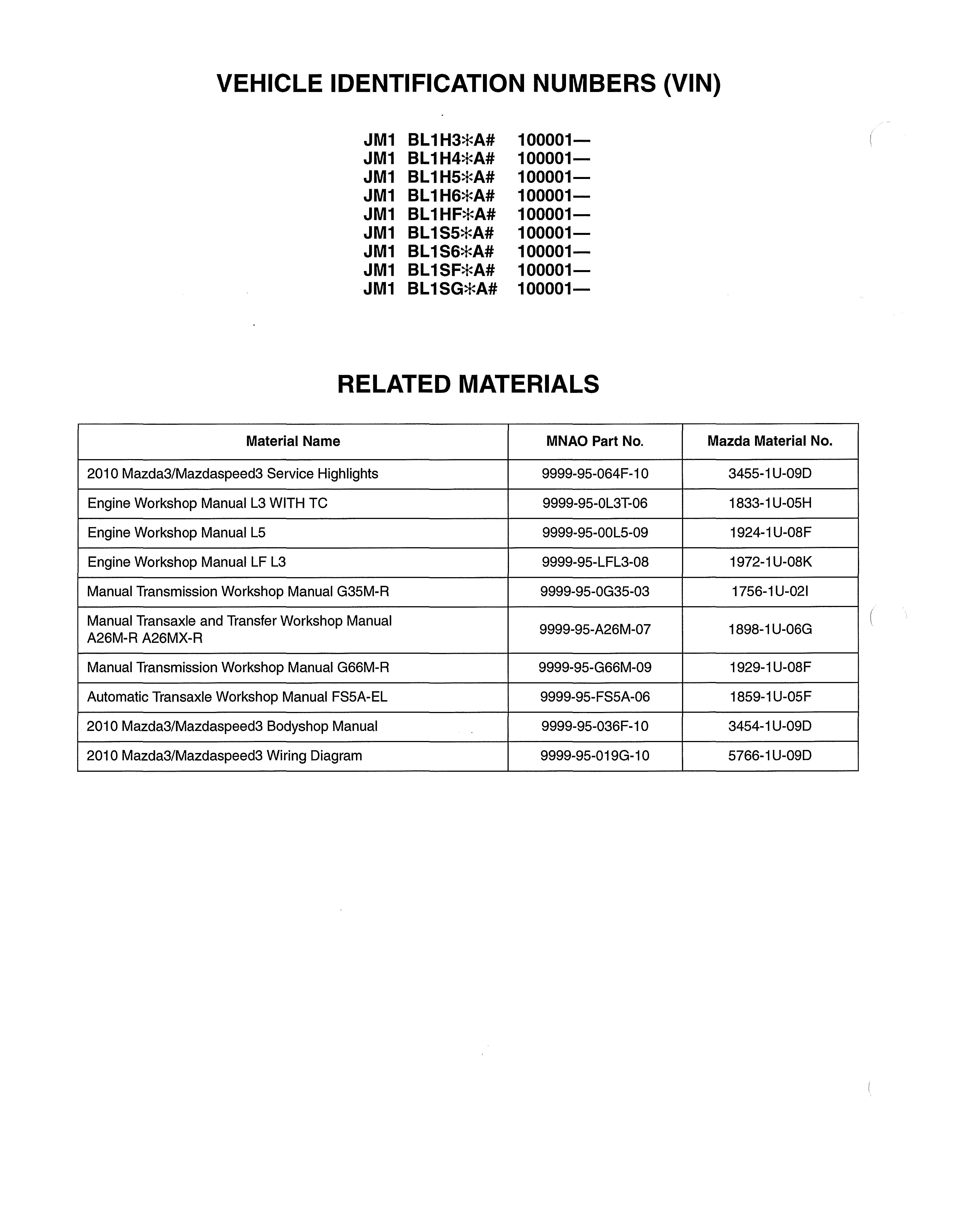
Manual Transmission Workshop Manual G35M-R 9999-95-0G35-03
Manual Transaxle and Transfer Workshop Manual 9999-95-A26M-07 A26M-R A26MX-R
Manual Transmission Workshop Manual G66M-R 9999-95-G66M-09
Automatic Transaxle Workshop Manual FS5A-EL 9999-95-FS5A-06
2010 Mazda3/Mazdaspeed3 Bodyshop Manual 9999-95-036F-10
2010 Mazda3/Mazdaspeed3 Wiring Diagram 9999-95-019G-10
Mazda Material No. 3455-1 U-09D 1833-1 U-05H 1924-1 U-08F 1972-1 U-08K 1756-1 U-021 1898-1 U-06G 1929-1 U-08F 1859-1 U-05 F 3454-1 U-09D 5766-1 U-09D
WARNING
Servicing a vehicle can be dangerous. If you have not received service-related training, the risks of injury, property damage, and failure of servicing increase. The recommended servicing procedures for the vehicle in this workshop manual were developed with Mazda-trained technicians in mind. This manual may be useful to non-Mazda trained technicians, but a technician with our service-related training and experience will be at less risk when performing service operations. However, all users of this manual are expected to at least know general safety procedures.
This manual contains "Warnings" and "Cautions" applicable to risks not normally encountered in a general technician's experience. They should be followed to reduce the risk of injury and the risk that improper service or repair may damage the vehicle or render it unsafe. It is also important to understand that the "Warnings" and "Cautions" are not exhaustive. It is impossible to warn of all the hazardous consequences that might result from failure to follow the procedures.

The procedures recommended and described in this manual are effective methods of performing service and repair. Some require tools specifically designed for a specific purpose. Persons using procedures and tools which are not recommended by Mazda Motor Corporation must satisfy themselves thoroughly that neither personal safety nor safety of the vehicle will be jeopardized.
The contents of this manual, including drawings and specifications, are the latest available at the time of printing, and Mazda Motor Corporation reserves the right to change the vehicle designs and alter the contents of this manual without notice and without incurring obligation.
Parts should be replaced with genuine Mazda replacement parts or with parts which match the quality of genuine Mazda replacement parts. Persons using replacement parts of lesser quality than that of genuine Mazda replacement parts must satisfy themselves thoroughly that neither personal safety nor safety of the vehicle will be jeopardized.
Mazda Motor Corporation is not responsible for any problems which may arise from the use of this manual. The cause of such problems includes but is not limited to insufficient service-related training, use of improper tools, use of replacement parts of lesser quality than that of genuine Mazda replacement parts, or not being aware of any revision of this manual.

, "
GENERAL INFORMATION .... 00-00
00-00 GENERAL INFORMATION

VEHICLE IDENTIFICATION NUMBER
(VIN) CODE . 00-00-2
VEHICLE IDENTIFICATION NUMBER (VIN) 00-00-2
HOW TO USE THIS MANUAL . ....... . 00-00-3
Range of Topics ..•.......•....... 00-00-3 Service Procedure 00-00-3
Symbols ................•....... 00-00-5
Advisory Messages ...........•.... 00-00-5
Troubleshooting Procedure 00-00-6 Procedures for Use . 00-00-7
UNITS . .......................... . 00-00-12
Conversion to SI Units (Systeme International d'Unites) .... . 00-00-12 Rounding Off. ................... . 00-00-12
Upper and Lower Limits 00-00-12
SERVICE CAUTIONS 00-00-13
Injury/damage Prevention Precautions .............•...... 00-00-13
Protection of the Vehicle . 00-00-13 Preparation of Tools and Measuring Equipment ............ . 00-00-13
Special Service Tools ......•.•.... . 00-00-13
Malfunction Diagnosis System 00-00-13
Negative Battery Cable Disconnection/ Connection ...............•.... 00-00-14
Oil Leakage Inspection • 00-00-14
Removal of Parts ............•.... . 00-00-15
Disassembly •................... . 00-00-15
Inspection During Removal, Disassembly ................... . 00-00-15
Arrangement of Parts ........•.... • 00-00-15
Cleaning of Parts 00-00-16
Reassembly ..•............•.... • 00-00-16
Adjustment 00-00-16
Rubber Parts and Tubing ...•.•...• . 00-00-17 Hose Clamps . 00-00-17
Torque Formulas ........•........ 00-00-17
Vise .......•...•.............. . 00-00-17
Dynamometer ...........•.•...... 00-00-18 SST . 00-00-18
ELECTRICAL SySTEM .............. 00-00-19 Electrical Parts •..•...•.......... . 00-00-19 Wiring Harness ............•...... 00-00-19 Connectors •..•......•........... 00-00-19
Terminals ..•....•.............. . 00-00-21
Sensors, Switches, and Relays 00-00-21 Wiring Harness ••••.............. . 00-00-21 Fuse .........•.....•...•....... 00-00-22
Direction of View for Connector ...... 00-00-22 Electrical Troubleshooting Tools ...... 00-00-23 Precautions Before Welding ........ . 00-00-24
INSTALLATION OF RADIO SYSTEM 00-00-25
JACKING POSITIONS, VEHICLE LIFT (2 SUPPORTS) AND SAFETY STAND (RIGID RACK) POSITIONS . 00-00-26
Jacking Positions . 00-00-26
Vehicle Lift Positions, Safety Stand Positions ........... . 00-00-27
TOWING 00-00-28
Vehicle Securing Position 00-00-29
IDENTIFICATION NUMBER
LOCATIONS 00-00-30
Vehicle Identification Number (VIN) 00-00-30 Engine Identification Number 00-00-30 SAE STANDARDS . . 00-00-31
ABBREVIATIONS . 00-00-32
PRE-DELIVERY INSPECTION . 00-00-33
Pre-Delivery Inspection Table ....... . 00-00-33
SCHEDULED MAINTENANCE . ...... . 00-00-34
Scheduled Maintenance Table for U.S.A., CANADA and Puerto Rico 00-00-34
Scheduled Maintenance Table for Mexico 00-00-37
GENERAL INFORMATION
00-00-1
JM1 BL1 H F*A0123456
I
Serial No.
0= Hiroshima L...- P:..,:I.:::::an..:.=,t 1= Hofu
Model year A= 2010
Check digit *= 0 to 9, X L...-
F= 2.0 L (LF) Federal/CANADA/Mexico
G= 2.0 L (LF) California
3= 2.3 L (L3 WITH TC) Federal/CANADA/Mexico
4= 2.3 L (L3 WITH TC) California
S= 2.S L (LS) Federal/CANADA/Mexico Engine 6= 2.S L (LS) California
H=SHB Body style S= 4SD
1= with Driver, Passenger, Side and Restraint system Curtain air bag module L...-
C_a_r_lin_e_a_nd_S_e_ri_es BL= Mazda3/Mazdaspeed3 World
VEHICLE IDENTIFICATION NUMBER (VIN)
JM1 BL1H3*A# 100001JM1 BL1H4*A# 100001JM1 BL1H5*A# 100001JM1 BL1H6*A# 100001JM1 BL 1HF*A# 100001JM1 BL1S5*A# 100001JM1 BL1S6*A# 100001JM1 BL1SF*A# 100001JM1 BL1SG*A# 100001-

GENERAL INFORMATION VEHICLE IDENTIFICATION NUMBER (VIN) CODE
id000000100200
manufacturer identification
JM1 = Mazda/passenger car
00-00-2 am3uuw0000624 id000000100300
GENERAL INFORMATION
HOW TO USE THIS MANUAL
Range of Topics
• This manual contains procedures for performing all required service operations. The procedures are divided into the following five basic operations: Removal/I nstallation Disas.sembly/Assembly Replacement Inspection Adjustment

• Simple operations which can be performed easily just by looking at the vehicle (i.e., removal/installation of parts, jacking, vehicle lifting, cleaning of parts, and visual inspection) have been omitted.
Service Procedure Inspection, adjustment
• Inspection and adjustment procedures are divided into steps. Important points regarding the location and contents of the procedures are explained in detail and shown in the illustrations.
id000000800100
SHOWS PROCEDURE ORDER FOR SERVICE SHOWS TIGHTENING TORQUE ,.., --'-------it SPECIFICATIONS Caution Connect the gauge set from under the vehicle to prevent contact with the drive belt and the cooling fan. am6xuw0000155 00-00-3 •
Repair procedure
1. Most repair operations begin with an overview illustration. It identifies the components, shows how the parts fit together, and describes visual part inspection. However, only removal/installation procedures that need to be performed methodically have written instructions.
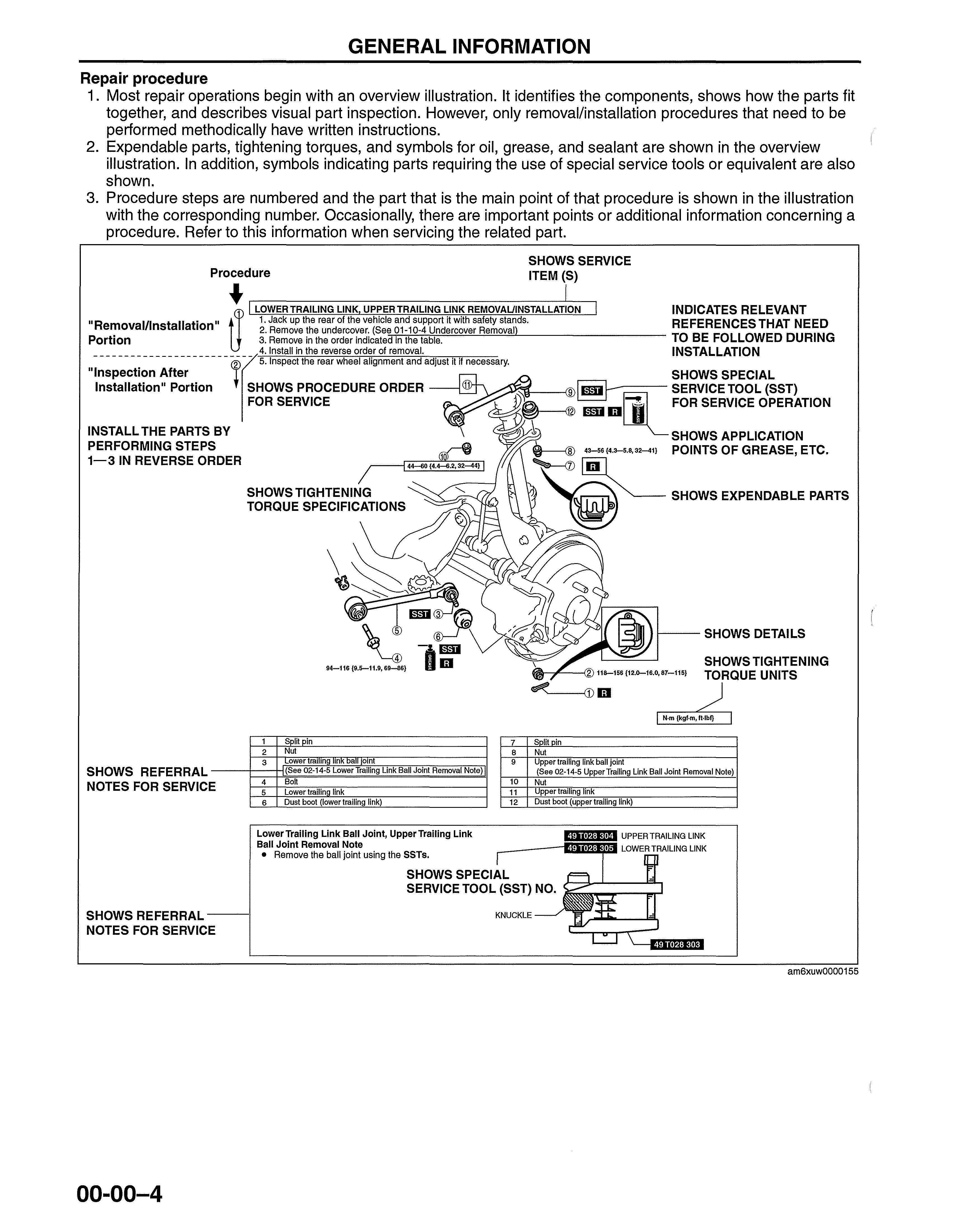
2. Expendable parts, tightening torques, and symbols for oil, grease, and sealant are shown in the overview illustration. In addition, symbols indicating parts requiring the use of special service tools or equivalent are also shown.
3. Procedure steps are numbered and the part that is the main point of that procedure is shown in the illustration with the corresponding number. Occasionally, there are important points or additional information concerning a procedure. Refer to this information when servicing the related part.
GENERAL INFORMATION
Procedure SHOWS SERVICE ITEM (S) "Removal/Installation" 1. Jack up the rear of the vehicle it with safety stands. RE FERENCES THAT NEED a LOWER TRAILING LINK UPPER TRAILING LINK REMOVAUINSTALLATION INDICATES RELEVANT • 2. Remove undercoyer: (See?1 104 Undercover Removal) TO BE FOLLOWED DURING Portion 3. Remove In the order indicated In the table. 4. Install in the reverse order of removal. INSTALLATION - 5. Inspect the rear wheel alignment and adjust it jf necessary. SHOWS SPECIAL Installation" Portion SHOWS PROCEDURE ORDER SERVICE TOOL (SST) FOR SERVICE _mlil FOR SERVICE OPERATION INSTALL THE PARTS BY \ SHOWS APPLICATION PERFORMING STEPS 43-56 {4.3-5.8,32-41) POINTS OF GREASE, ETC. 1-3 IN REVERSE ORDER SHOWS EXPENDABLE PARTS SHOWS REFERRAL NOTES FOR SERVIC E SHOWS REFERRAL NOTES FOR SERVICE 00-00-4 1 Split pin 2 Nut 3 ower trallng inK oall oint 7 B 9 Split pin Nut Upper trailing link ball joint SHOWS DETAILS SHOWS TIGHTENING TORQUE UNITS (See 02-1 Joint Removal Note) I (See 02-14-5 Upper Trailing Link Ball Joint Removal Note) 4 Bolt 5 Lower trailing link 6 Dust boot (lower trailing link) LowerTrailing Link Ball Joint, Upper Trailing Link Ball Joint Removal Note • Remove the ball joint using the SSTs. 10 Nut 11 Upper trailing link 12 Dust boot (upper trailing link) SHOWS SPECIAL SERVICE TOOL (SST) NO. KNUCKLE am6xuw0000155
Symbols
•
Advisory Messages
Warning
Caution
•
Note
•
Specification

•
•
GENERAL INFORMATION
There are eight symbols indicating oil, grease, fluids, sealant, and the use of SST or equivalent. These symbols show application points or use of these materials during service.
Meaning Kind New appropriate I Apply oil engine oil or gear oil • Apply brake fluid New appropriate brake fluid • Apply automatic New appropriate automatic transaxlel transaxlel transmission fluid transmission fluid Appropriate I Apply grease grease ·_1 Apply sealant Appropriate sealant G Apply petroleum Appropriate jelly petroleum jelly iii Replace part O-ring, gasket, etc. ED Use SST or Appropriate tools equivalent
Symbol
You will find several Warnings, Cautions, Notes, Specifications and Upper and Lower Limits in this manual.
•
A Warning indicates a situation in which serious injury or death could result if the warning is ignored.
•
A Caution indicates a situation in which damage to the vehicle or parts could result if the caution is ignored.
A Note provides added information that will help you to complete a particular procedure.
The values indicate the allowable range when performing inspections or adjustments.
and lower limits
Upper
The values indicate the upper and lower limits that must not be exceeded when performing inspections or adjustments. 00-00-5 •
Troubleshooting Procedure
Basic flow of troubleshooting
CUSTOMER ARRIVES
WARNING LlGHT* ON/FLASHING
NO WARNING LlGHT* WITH SYMPTOM
CHECK FOR PRIORITIZED DTC
DIAGNOSE BY DTC (ON-BOARD DIAGNOSTIC)
• DTCTABLE
• DTC TROUBLESHOOTING FLOW
*: INDICATOR LIGHTS AND WARNING LIGHTS THAT INDICATE MALFUNCTIONS
DTC troubleshooting flow (on-board diagnostic)
• CHECK DTC
• IGNITION ON TEST, IDLING TEST
r WITHOUT DTC
DIAGNOSE BY SYMPTOM (SYMPTOM TROUBLESHOOTING)

1. DIAGNOSTIC INDEX
2. QUICK DIAGNOSIS CHART (IF MENTIONED)
3. SYMPTOM TROUBLESHOOTING acxuuw00000444
• Diagnostic trouble codes (DTCs) are important hints for repairing malfunctions that are difficult to simulate. Perform the specific DTC diagnostic inspection to quickly and accurately diagnose the malfunction.
• The on-board diagnostic function is used during inspection. When a DTC is shown specifying the cause of a malfunction, continue the diagnostic inspection according to the items indicated by the on-board diagnostic function.
Diagnostic index
• The diagnostic index lists the symptoms of specific malfunctions. Select the symptoms related or most closely relating to the malfunction.
Quick diagnosis chart (If mentioned)
• The quick diagnosis chart lists diagnosis and inspection procedures to be performed specifically relating to the· cause of the malfunction.
Symptom troubleshooting
• Symptom troubleshooting quickly determines the location of the malfunction according to symptom type.
GENERAL INFORMATION
I
DTC
00-00-6
Procedures for Use
Using the basic inspection (section 05)
• Perform the basic inspection procedure before symptom troubleshooting.
• Perform each step in the order shown.
• The reference column lists the location of the detailed procedure for each basic inspection.
• Although inspections and adjustments are performed according to the reference column procedures, if the cause of the malfunction is discovered during basic inspection, continue the procedures as indicated in the action column.
SHOWS INSPECTION ORDER SHOWS ITEM NAMES FOR DETAILED PROCEDURES

lBASIC INSPECTION
I'STEP INSPECTION ACTION
SHOW POINTS REQUIRING ATTENTION BASED ON
INSPECTION R ESULTS
1 Perform the mechanical system test. Yes Go to the next step. (See 05-13-3 MECHANICAL SYSTEM TEST.) No Repair or replace any malfunctioning parts according to Is mechanical system normal? the inspection result.
2 Turn the ignition switch to the ON position. Yes Go to the next step. When the selector lever is moved, does the selector No Inspect the selector lever and TR switch. Repair or illumination indicate synchronized position to the replace malfunctioning parts. lever location? Also, when other ranges are selected (See 05-14-5 SELECTOR LEVER INSPECTION.) from N or P during idling, does the vehicle move (See 05-13-10 TRANSMISSION RANGE (TR) SWITCH within 1-2 s? INSPECTION.) If the selector lever and TR switch are normal, go to the next step.
3 Inspect the ATF color condition. Yes Go to the next step. (See 05-13-8 AUTOMATIC TRANSMISSION No Repair or replace any malfunctioning parts according to FLUID (ATF) INSPECTION.) the inspection result. Are ATF color and odor normal? Flush ATX and cooler line as necessary.
4 Perform the line pressure test. Yes Go to the next step. (See 05-13-3 Line Pressure Test.) No Repair or replace any malfunctioning parts according to Is the line pressure normal? the inspection result.
5 Perform the stall test. Yes Go to the next step. (See 05-13-4 Stall Speed Test.) No Repair or replace any malfunctioning parts according to Is the stall speed normal? the inspection result.
Inspect the voltage at the following TCM terminals. Yes Go to the next step.
(See 05-13-29 TCM INSPECTION.) No Repair or replace any malfunctioning parts according to
• Terminal2J (TFT sensor) the inspection result.
• Terminals 10, 2B, 2C, 2E (TR switch)
• Terminal 2G (turbine sensor)
• Terminal2D (down switch)
• Terminal 21 (up switch)
• Terminal 1E (M range switch)
• Terminal1W (steering shift switch) Is the voltage normal?
GENERAL INFORMATION
REFERENCE COLUMN
am6xuw0000155 00-00-7 •
GENERAL INFORMATION
Using the OTe troubleshooting flow
• DTC troubleshooting flow shows diagnostic procedures, inspection methods, and proper action to take for each DTC.
,TROUBLE CONDITION
POSSIBLE CAUSE describes possible point(s) of malfunction tep Indicates the inspection s No. to be performed (01 and 05 section)
STEP shows the order of troubleshoo ting
INSPECTION describes the method to quickly determine the malfunctioning part(s).
DETECTION CONDITION describes the condition e DTC is under which th
DTC P0103 detected.
DTC P0103 MAF circuit high input PCM monitors input voltage from TP sensor after ignition key is turned on, If input voltage at PCM terminal 68 is above 8,25 V, PCM determines that TP circuit has malfunction,
DETECTION Diagnostic support note

This is a continuous monitor (CCM), CONDITION MIL illuminates if PCM detects the above malfunction during first drive cycle, Therefore, PENDING CODE is not available, FREEZE FRAME DATE is available, DTC is stored in the PCM memory,
POSSIBLE ,. MAF sensor malfunction
CAUSE Connector or terminal malfunction Open circuit in wiring between MAF sensor terminal D and PCM terminal 36 Open circuit in MAF sensor ground circuit
In dicates the circuit to be spected in (0 1 and 05 ction) se
ACTION
Go to next step, No Record FREEZE FRAME DATA on repair order, then go to next step, Yes Perform repair or diagnosis according to available repair information, If vehicle is not repaired, then go to next step, No Go to next ste Yes Intermittent concern is existing. Go to INTERMITTENT CONCERNS TROUBLESHOOTING procedure.
In co dicates the nnector ated to the spection rei in ACTION describes the appropriate action to be taken according to ---il----+
• Connect diagnostic tool to DLC-2.
• Start engine.
• Access MAF V PID using diagnostic tool. Is MAF V PiD within 0.2 - 8.3 V?
INSPECT POOR CONNECTION OF MAF SENSOR CONNECTOR
• Turn ignition key to OFF.
Disconnect MAF sensor connector.
• Check for poor connection (damaged, pulledout terminals, corrosion etc.).
• Are there any malfunctions?
(See 01-03-33 INTERMITTENT CONCERN TROUBLESHOOTING)
the result (Yes/No) of the INSPECTION. 4
No Go to next step. Yes Repair or replace terminals, then go to Step 8.
Reference item(s) to perform ACTION.
MAFSENSOR HARNESS SIDE
FROM MAIN RELAY @@ @ (j)
CONNECTOR I A Diagnostic procedure STEP 2 3 INSPECTION VERIFY FREEZE FRAME DATA HAS BEEN RECORDED Has FREEZE FRAME DATA been recorded? VERIFY RELATED REPAIR INFORMATION AVAILABILITY
PCM ®h 36 PCM HARNESS SIDE CONNECTOR I""'"- rII 1 11Pl I I DI Il 1 1 1 1 I II I 1 1 1 1 HI M
V
• Are related Service Bulletins and/or on-line re air information available? VERIFY CURRENT INPUT SIGNAL STATUS IS CONCERN INTERMITTENT OR CONSTANT
Yes
00-00-8
am6xuw0000155
GENERAL INFORMATION
Using the diagnostic index
• Malfunction symptoms are listed in the diagnostic index under symptom troubleshooting.

• The exact malfunction symptoms can be selected by following the index.
No. TROUBLESHOOTING ITEM DESCRIPTION Page
1 Melting of main or other fuses - (See 01-03-6 MELT NO.1 MAIN OR OTHER FUSE)
2 MIL comes on MIL is illuminated incorrectly. (See 01-03-7 NO.2 MIL COMES ON)
3 Will not crank
Starter does not work. (See 01-03-8 NO.3 WILL NOT CRANK)
Hard starVlong crank/erratic starVerratic Starter cranks engine at normal (See 01-03-9 NO.4 HARD START/
4 speed but engine requires excessive crank cranking time before starting. LONG CRANK/ERRATIC CRANK)
5 Engine stalls. I After starVat idle Engine stops unexpectedly at idle (See 01-03-11 NO.5 ENGINE-STALLS and/or after start. AFTER START/AT IDLE)
6 Cranks normally but will not start
7 Slow return to idle
Starter cranks engine at normal (See 01-03-15 NO.6 CRANKS speed but engine will not run. NORMALLY BUT WILL NOT START)
Engine takes more time than normal (See 01-03-19 NO.7 SLOW RERUN to return to idle speed. TO IDLE)
Engine speed fluctuates between
8 Engine runs rough/rolling specified idle speed and lower (See 01-03-20 NO.8 ENGINE RUNS speed and engine shakes ROUGH/ROLLING IDLE) excessively.
Engine speed continues at fast idle
9 Fast idle/runs on after warm-up. (See 01-03-23 NO.9 FAST IDLE/RUNS
Engine runs after ignition key is ON) turned to OFF.
Engine stops unexpectedly at begin- (See 01-03-24 NO. 10 LOW IDLE/
10 Low idle/stalls during deceleration ning of deceleration or recovery from deceleration. STALLS DURING DECELERATION)
•
acxuuw00000447 00-00-9
Using the quick diagnosis chart
• The chart lists the relation between the symptom and the cause of the malfunction.
• The chart is effective in quickly narrowing down the relation between symptom and cause of the malfunction. It also specifies a range of common causes when multiple malfunction symptoms occur.

• The appropriate diagnostic inspection relating to a malfunction cause as specified by the symptoms can be selected by looking down the diagnostic inspection column of the chart.
PARTS WHICH MAY BE THE CAUSE OF PROBLEMS
SYMPTOM QUICK DIAGNOSTIC
Troubleshooting item
GENERAL INFORMATION
-f------... THE
THE ACTUALSYMPTOM 00-00-10
CHART Possible factor PART WHICH MAY BE
SYMPTOM G) CHOOSE
1
2
3
4
5
6
7
8
9
10
11
12
13
14 Poor
15
16
17
18
19 Exhaust
20 Fuel odor
21 Engine
22 Vibration
23 NC does
24 NC
25 NC does
conditions ti:Xhaust
smell el refill concerns I filling shut off issues 29 Intermittent concerns 30 Constant voltage 31 Spark plug condition 32 Automatic transaxle concerns
o r. o <D 6 c: o t5 c: :::J 'lij E x x x
x
(See
AUTOMATIC TRANSAXLE SYMPTOM TROUBLESOOTING) am6xuw0000155
Melts of main or other fuse ""
MIL comes on
Will not crank
Hard to startllong crank/erratic startlerratic crank
Engine stalls IAfter startlat idle
Cranks normally but will not start
Slow return to idle
Engine runs rough/rolling idle
Fast idle/runs on
Low idle/stalls during deceleration Engine stalls/quits Acceleration/cruise Engine runs rough Acceleration/cruise Misses Acceleration/cruise
Buck/jerk Acceleration/cruise/ deceleration Hesitation/stumble Acceleration Surges Acceleration/cruise
Lack/loss of power Acceleration/cruise
Knocking/pinging Acceleration/cruise
fuel economy
Emissions compliance
High oil consumption/leakage
Cooling system concerns IOverheating
Cooling system concerns I Runs cold
smoke
(in engine compartment)
noise
concerns (engine)
not work sufficiently
always on/ NC compressor runs continuously
not cut off under wide open throttle
sulphur
Upshiftldownshiftl engagement ®
x x x
x x x x x x x x x x x x x x x x x x x x x x x x x x x x x x x x x x x x x x x x x x x x x x x x x x x I x x x x x x x x x x x x x x x
05-01
GENERAL INFORMATION
Using the symptom troubleshooting

• Symptom troubleshooting shows diagnostic procedures, inspection methods, and proper action to be taken for each trouble symptom.
DESCRIPTION describes what TROUBLE SYMPTOM kind of TROUBLE SYMPTOM \
POSSIBLE CAUSE describes possible point of malfunction STEP showS
"
• When accelerator pedal is depressed for driveway, engine speed increase but vehicle speed increase DESCRIPTION slowly.
14 "" Engine flares up or slips when upshifting or down shifting
• When accelerator is depressed while driving, engine speed increases but vehicle not.
• There is clutch slip because clutch is stuck or line pressure is low.
- Clutch stuck, slippage (forward clutch, 3-4 clutch, 2-4 brake band, one-way clutch 1, one-way clutch 2)
• Line pressure low
• Malfunction or mis-adjustment of TP sensor
• Malfunction of VSS
• Malfunction of inpuVturbine speed sensor
• Malfunction of sensor ground
• Malfunction of shift solenoid A, B or C
• Malfunction of TCC solenoid valve
POSSIBLE
• Malfunction of body ground CAUSE
• Malfunction of throttle cable
• Malfunction of throttle valve body
- Poor operating of mechanical pressure
• Selector lever position disparity
• TR switch position disparity
Note the order of troubleshootmg.
• Before following troubleshooting steps, make sure that Automatic Transaxle On-board Diagnostic and Automatic Transaxle Basic Inspection are conducted.
Refere item(s additio inform to perf INSPE orm CTION.
Diagnostic procedure
STEP INSPECTION ACTION 1
• Is line pressure okay? Yes Go to next step. nce No Repair or replace any defective parts according to inspection results. ) for 2
• Is shift point okay? Yes Go to next step nal (See 05-17-5 ROAD TEST) No Go to symptom troubleshooting No.9 "Abnormal shift". ation 3
• Stop engine and turn ignition switch on. Yes • Overhaul control valve body and repair or replace any
• Connect diagnostic tool to DLC-2. defective parts.
• Simulate SHIFT A, SHIFT B and SHIFT C PIDs (See ATXWorkshop Manual GF4A-EL (1666-1A-99F»
forON.
• Is operating sound of shift solenoids heard?
INSPE descri metho quickly determ malfun part(s)
CTION besthe d to ine the ctioning 4
• Verify test results.
• If problem remains, replace or overhaul transaxle and repair or replace defective parts.
(See 05-17-15 AUTOMATIC TRANSAXLE REMOVEVAUINSTALLATION)
No • Inspect for bend, damage, corrosion or loose connection if shift solenoid A, B, or C terminal on ATX.
• Inspect for shift solenoid mechanical stuck. (See 05-17-14 Inspection of Operation)
• If shift solenoids are okay, inspect for open or short circuit between PCM connector terminal A, B or C.
- If okay, return to diagnostic index to service any additional symptoms.
- If malfunction remains, inspect related Service Bulletins and/or On-line Repair Information and perform repair or diagnosis.
- If vehicle is repaired, troubleshooting completed.
- If vehicle is not repaired or additional diagnostic information is not available, replace or reprogram PCM.
=1
ACTION descri bes the appropriate action to be taken according to the result (Yes/No) of the INSPECTION.
How to perform ACTION is described in the relative material shown. Reference item(s) to perform ACTION.
am6xuw0000156 00-00-11 •
UNITS
Electric current A (ampere)
Electric power W (watt)
Electric resistance ohm
Electric voltage V (volt)
Length mm (millimeter) in (inch) kPa (kilo pascal)
Negative pressure mmHg (millimeters of mercury) inHg (inches of mercury) kPa (kilo pascal)
Positive pressure (kilogram force per square centimeter) psi (pounds per square inch)
Number of rpm (revolutions per minute) revolutions N·m (Newton meter) kgf.m (kilogram force meter)
Torque kgf·cm (kilogram force centimeter) ft·lbf (foot pound force) in·lbf (inch pound force) L (liter) US qt (U.S. quart) Imp qt (Imperial quart)
Volume ml (milliliter) cc (cubic centimeter) cu in (cubic inch) fl oz (fluid ounce)
Weight g (gram) oz (ounce)
Conversion to SI Units (Systeme International d'Unites)
• All numerical values in this manual are based on 81 units. Numbers shown in conventional units are converted from these values.

Rounding Off
• Converted values are rounded off to the same number of places as the 81 unit value. For example, if the 81 unit value is 17.2 and the value after conversion is 37.84, the converted value will be rounded off to 37.8.
Upper and Lower Limits
• When the data indicates upper and lower limits, the converted values are rounded down if the 81 unit value is an upper limit and rounded up if the 81 unit value is a lower limit. Therefore, converted values for the same 81 unit value may differ after conversion. For example, consider 2.7 kgf/cm 2 in the following specifications:
210-260 kPa {2.1-2.7 kgf/cm 2 , 30-38 psi}
270-310 kPa {2.7-3.2 kgf/cm 2 , 39-45 psi}
• The actual converted values for 2.7 kgf/cm 2 are 264 kPa and 38.4 psi. In the first specification, 2.7 is used as an upper limit, so the converted values are rounded down to 260 and 38. In the second specification, 2.7 is used as a lower limit, so the converted values are rounded up to 270 and 39.
GENERAL INFORMATION
id000000801600
00-00-12
SERVICE CAUTIONS
Injury/damage Prevention Precautions
• Depending on the vehicle, the cooling fan may operate suddenly even when the ignition is switched to off. Therefore, keep hands and tools away from the cooling fan even if the cooling fan is not operating to prevent • injury to personnel or damage to the cooling fan. Always disconnect the negative battery cable when servicing I I I I the cooling fan or parts near the cooling fan.

Protection of the Vehicle
• Always be sure to cover fenders, seats and floor areas before starting work.
Preparation of Tools and Measuring Equipment
• Be sure that all necessary tools and measuring equipment are available before starting any work.
Special Service Tools
• Use special service tools or equivalent when they are required.
Malfunction Diagnosis System
• Use the Mazda modular diagnostic system (M-MDS) or equivalent for malfunction diagnosis.
GENERAL INFORMATION
id000000800200
am3uuw0000192 am3uuw0000193 00-00-13
GENERAL INFORMATION
Negative Battery Cable Disconnection/Connection
• Periorm the following system initialization after disconnecting the negative battery cable.
SYSTEM PAGE
Steering angle sensor (See 09-18-20 STEERING ANGLE SENSOR INITIALIZATION PROCEDURE.)
Power window system (See 09-12-17 POWER WINDOW INITIALIZATION PROCEDURE.)
Required procedure following negative battery cable disconnection

SAS control module
Disconnect the negative battery cable and wait for 1 min. or more to allow the back-up power supply to deplete its stored power.
Clock and audio
The clock and audio memory settings will be erased, therefore record the clock and audio settings prior to disconnecting, and reset them after reconnecting.
Audio
The DTC memory will be erased, therefore record the DTC content prior to disconnecting.
Oil Leakage Inspection
• Use either of the following procedures to identify the type of oil that is leaking:
Using UV light (black light)
1. Remove any oil on the engine or transaxleltransmission.
Note
• Referring to the fluorescent dye instruction manual, mix the specified amount of dye into the engine oil or ATF (or transaxleltransmission oil).
2. Pour the fluorescent dye into the engine oil or ATF (or transaxleltransmission oil).
3. Allow the engine to run for 30 min.
4. Inspect for dye leakage by irradiating with UV light (black light), and identify the type of oil that is leaking.
5. If no dye leakage is found, allow the engine to run for another 30 min. or drive the vehicle then reinspect.
6. Find where the oil is leaking from, then make necessary repairs.
Note
• To determine whether it is necessary to replace the oil after adding the fluorescent dye, refer to the fluorescent dye instruction manual.
Not using UV light (black light)
1. Gather some of the leaking oil using an absorbent white tissue.
2. Take samples of engine oil and ATF (or transaxleltransmission oi!), both from the dipstick, and place them next to the leaked oil already gathered on the tissue.
3. Compare the appearance and smell, and identify the type of oil that is leaking.
4. Remove any oil on the engine or transaxlel transmission.
5. Allow the engine to run for 30 min.
6. Check the area where the oil is leaking, then make necessary repairs.
00-00-14 ATFOR TRANSAXLEI TRANSMISSION OIL ENGINE OIL ;;f1 LEAKED OIL am3uuw0000192
GENERAL INFORMATION
Removal of Parts
• While correcting a problem, also try to determine its cause. Begin work only after first learning which parts and subassemblies must be removed and disassembled for replacement or repair. After removing the part, plug all holes and ports to prevent foreign material from entering.

Disassembly
• If the disassembly procedure is complex, requiring many parts to be disassembled, all parts should be marked in a place that will not affect their performance or external appearance and identified so that reassembly can be performed easily and efficiently.
Inspection During Removal, Disassembly
• When removed, each part should be carefully inspected for malfunction, deformation, damage and other problems.
Arrangement of Parts
• All disassembled parts should be carefully arranged for reassembly.
• Be sure to separate or otherwise identify the parts to be replaced from those that will be reused.
am3uuw0000192
am3uuw0000192
am3uuw0000192
am3uuw0000192
•
00-00-15
Full download: http://manualplace.com/download/mazda-3-mazda-speed-3-2nd-gen-workshop-manual/
Cleaning of Parts
GENERAL INFORMATION
• All parts to be reused should be carefully and thoroughly cleaned in the appropriate method.
Warning
• Using compressed air can cause dirt and other particles to fly out causing injury to the eyes. Wear protective eye wear whenever using compressed air.
am3uuw0000192
Reassembly
• Standard values, such as torques and certain adjustments, must be strictly observed in the reassembly of all parts.
• If removed, the following parts should be replaced with new ones: Oil seals Gaskets a-rings Lock washers Cotter pins Nylon nuts
• Depending on location: Sealant and gaskets, or both, should be applied to specified locations. When sealant is applied, parts should be installed before sealant hardens to prevent leakage. Oil should be applied to the moving components of parts. Specified oil or grease should be applied at the prescribed locations (such as oil seals) before reassembly.

Adjustment
• Use suitable gauges and testers when making adjustments.
am3uuw0000192
am3uuw0000193
00-00-16
Mazda 3 Mazda Speed 3 2nd Gen Workshop Manual
This is the cut pages sample. Download all 3358 page(s) at: ManualPlace.com
