
KXX, and K9K K9K engine
Engine workshop repair manual
"The repair methods given by the manufacturer in this document are based on the technical specifications current when it was prepared.
The methods may be modified as a result of changes introduced by the manufacturer in the production of the various component units and accessories from which his vehicles are constructed."
All copyrights reserved by Renault.
The reproduction or translation in part of whole of the present document, as well as the use of the spare parts reference numbering system, are prohibited without the prior written consent of Renault.
© Renault s.a.s. 2006
77 11 328 422MARCH 2004Edition Anglaise
Edition 2 Renault Kxx And K9k Engine Workshop Repair Manual Full download: http://manualplace.com/download/renault-kxx-and-k9k-engine-workshop-repair-manual/
K9K engine
Contents
Page
10AENGINE AND LOWER ENGINE ASSEMBLY
Engine: Specifications10A-1
Engine: Precautions for repair10A-4
Engine: Parts and consumables for the repair work10A-14
Upper engine: Tightening torque10A-15
Lower engine: Tightening torque10A-20
Diesel injection: Tightening torque10A-23
Accessories belt: Tightening torque10A-26
Upper engine: Specifications10A-28
Engine peripherals: Specifications10A-36
Standard replacement10A-46
Special tooling10A-47 Equipment10A-65
Engine: Dismantling10A-84
Accessories belt: Removal10A-89
Timing - cylinder head: Removal10A-90
Cylinder head: Dismantling10A-113
Upper engine: Cleaning10A-129
Upper engine: Checking10A-135
Cylinder head: Refitting10A-144
Cylinder block: Dismantling10A-192
Running gear:Removal10A-204
10AENGINE AND LOWER ENGINE ASSEMBLY
Piston base cooling jet: Removal10A-207
Lower engine: Cleaning10A-209
Lower engine: Check10A-211
Piston base cooling jet: Refitting10A-224
Running gear Refitting10A-227
Cylinder block: Refitting10A-239
Timing - cylinder head: Refitting10A-280
Accessories belt: Refitting10A-326 Engine: Refitting10A-329
Timing belt: Removal10A-336
Timing belts: Refitting10A-351
K9K engineContentsPage
ENGINE AND LOWER ENGINE ASSEMBLY
Engine: Specifications 10A
Details of markings
107307 113741
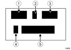
The engine can be identified by markings (6) located on the cylinder block.
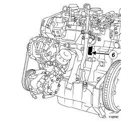
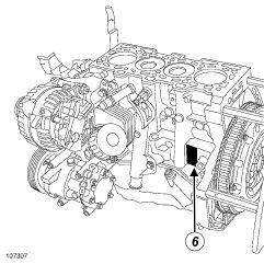
The markings consist of: - (1) : the engine type - (2) : the engine approval letter - (3) : the engine suffix - (4) : the factory where the engine was fitted - (5) : the engine production number
19858
10A-1
I - ENGINE IDENTIFICATION
II
10A-2
AND LOWER ENGINE ASSEMBLY
10A
ENGINE
Engine: Specifications
- ENGINE SPECIFICATION TABLES
VehicleAfterSales Type: Engine type Engine suffix Cubic capacity (cc) Bore (mm) Stroke (mm) Compression ratio
Renault CLIO II XB07 XB1W XB24 K9K 700 1461 76 80.5 18.25:1 XB08702 XB07704 XB24704 17.9:1 XB23 XB2E 706 XB09710 18.25:1 XB2G712 17.9:1
Renault KANGOO XC07 K9K 700 1461 76 80.5 18.25:1 XC08 XC1S 702 XC07 XC08 704 XC1R704 17.6: 1 XC09710 18.25:1 XC1E714 17.9:1 XC1F716 XC1G718
Renault MEGANE II XM0F K9K 722 1461 76 80.5 18.25:1 XM0T722 17.6:1 XM1F724 17.9:1 XM02728, 729 17.9:1 XM13728 17.6: 1 XM1E732 15.3:1 Renault CLIO III XR0H K9K 764 1461 76 80.5 15.3:1 XR0F766 17.9:1 XR0G768
ENGINE AND LOWER ENGINE ASSEMBLY Engine: Specifications 10A
VehicleAfterSales Type:
Engine type Engine suffix
Cubic capacity (cc) Bore (mm) Stroke (mm) Compression ratio
Renault MODUS
XP0D K9K
750 1461 76 80.5
17.6: 1 XP08 XP0E 752 XP0F760 17.9:1 XP0G762 ,768 XP0H764 15.3:1 XP0F766 17.9:1
Renault DACIA XS0J K9K 790 1461 76 80.5 17.9:1 XS0K792
Nissan ALMERA -K9K260 1461 76 80.5 18.25:1
Nissan MICRA -K9K270, 272, 274, 276 1461 76 80.5 18.25:1
10A-3
ENGINE AND LOWER ENGINE ASSEMBLY
Engine: Precautions for repair
Equipment required
offset thread repair kit
I - SAFETY
General information
All information contained in these manuals is intended exclusively for automotive industry professionals.
The documentation is intended to cover all vehicles in the RENAULT range throughout the world, but may not cover equipment designed for use in specific countries.
The methods and fault finding procedures recommended and described in this manual have been designed by automotive industry repair professionals.
a - General recommendations
Observe basic principles of vehicle repair.
The quality of repair depends first and foremost on the care exercised by the person in carrying it out.
To ensure good repair:
-use recommended professional products and original Renault parts,
-observe the tightening torques, -replace the recommended roll pins, nuts or bolts, after each removal,
-clean and degrease the sections to be bonded, to ensure they bond correctly.
The design quality of our vehicles demands that nothing is left to chance in making a good repair, and it is essential to refit parts or components exactly as they were originally (for instance: heat shields, wiring routing, pipe routing).
Use professional products and apply them with care, for example do not apply too much sealant to the joint face.
b - Special tooling - ease of use
The repair procedures have been designed using special tools; they must therefore be carried out using these tools to ensure a high degree of working safety and quality of repair.
The equipment we have approved has undergone careful research and testing, and must be used and maintained with care.
c - Reliability - updating
Since component specifications are subject to change during their commercial life, it is essential to check whether there are any Technical Note updates when seeking information.
d - Safety
Certain devices and parts must be handled with particular attention to safety and cleanliness and, above all, with due care.
The safety symbol used in this manual indicates that special attention must be paid to the procedure or the tightening torque values.
WARNING
Do not use flammable products to clean parts.
Working safely:
-use appropriate tools which are in good condition (using « multipurpose » tools, such as adjustable pliers, should be avoided wherever possible), -adopt a correct posture and technique when performing heavy work or lifting loads, -check that the working area is clean and tidy during the operation, -use personal protection (gloves, safety goggles, work shoes, masks, skin barrier creams, etc.), -always follow the safety instructions associated with the operation to be performed, -do not smoke when working on vehicles, -do not use toxic products in unventilated rooms, -do not ingest any chemicals (brake fluid, coolant, etc.).
Respecting the environment: -sort waste according to its particular qualities, -do not burn waste products (tyres, etc.).
e - Conclusion
The procedures contained in this document merit your attention. Please read them carefully in order to reduce the risk of injury, and avoid using incorrect procedures that could damage the vehicle or make it dangerous to use.
Following the recommended procedures will help you to provide a quality of service which will ensure the vehicles achieve the highest levels of performance and reliability.
10A-4
10A
ENGINE AND LOWER ENGINE ASSEMBLY
Engine: Precautions for repair
Maintenance and repair operations must be carried out under the proper conditions to ensure that our vehicles run safely and reliably.
II - CLEANLINESS
Risks relating to contamination
The high-pressure direct injection system is highly sensitive to contamination. The risks caused by contamination are:
-damage to or destruction of the high-pressure injection system, -a component seizing, -a component not being properly sealed.
All After-Sales operations must be performed under very clean conditions. Having carried out an operation in good conditions means that no impurities (particles a few microns in size) have penetrated the system during dismantling.
The cleanliness principle must be applied from the filter to the injectors.
What are the sources of contamination? -metal or plastic chips, -paint, -fibres: •cardboard, •brushes, •paper, •clothing, •cloth, -foreign bodies such as hair, -ambient atmosphere, -etc.
WARNING
Cleaning the engine using a high-pressure washer is prohibited because of the risk of damaging connections. In addition, moisture may collect in the connectors and create electrical connection faults.
a - Cleaning cloths
Use lint free cleaning cloths (part number 77 11 211 707 ).
The use of rags or ordinary paper towels is prohibited: these produce lint and lose fibres, which then contaminate the fuel circuit.
Each cloth must only be used once.
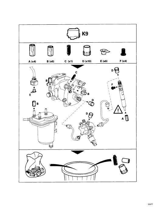
b - Blanking plugs
The blanking plugs are used to cap the fuel circuit once it is opened and to therefore prevent contaminants from entering.
A set of blanking plugs should be used once only and used plugs must be discarded after use: once used, the plugs are soiled and cleaning them is not sufficient to make them reusable.
Unused plugs must also be discarded and not used again for any other operation on an injection system.
Blanking plug kit part number:
-K9K ( DELPHI injection): 77 01 206 804
-K9K ( SIEMENS injection): 77 01 476 857
c - Protective bags
Use hermetically resealable plastic bags, using adhesive tape, for example, to store components which will be refitted and reused. Stored parts will therefore be less subject to the risk of contamination.
These bags must be used once only: once they have been used, they are to be discarded.
d - Cleaning products
Two cleaning products can be used:
-an aerosol spray brake cleaner (part number 77 11 226 128 ).
-an injector cleaner (part number 77 11 224 188 ),
To use the injector cleaner, be sure to have a clean brush in good condition (the brush must not lose any bristles) as well as a clean container which has no impurities in it.
Note: Use a new injector cleaner each time work is carried out (a used cleaning agent will contain impurities).
10A-5
10A
ENGINE AND LOWER ENGINE ASSEMBLY
Engine: Precautions for repair 10A
III - GENERAL RECOMMENDATIONS
1 - Advice to be followed before any operation
1) Carry out the work in a clean working area and take care to protect removed components from dust using plastic bags which are hermetically resealable, for example.
2) Always order the following from the Parts Department before carrying out work:
- a new blanking plug kit ; these are specific to the engine
-a sufficient number of lint free cleaning cloths
-one of the two cleaning products for fuel pipe unions,
- the parts always to be replaced after each removal operation mentioned in the operational procedures specific to the vehicle.
3) Wear safety goggles fitted with side shields to prevent the cleaning product from splashing the eyes.
4) Wear latex safety gloves to avoid prolonged contact with the skin.
Note:
If wearing leather protective gloves, cover these with latex gloves.
5) Before any operation on the injection system, using plastic bags or clean cloths, protect:
-the accessories and timing belts, -the electrical accessories (starter, alternator, powerassisted steering pump, sensors and electrical connectors),
-the flywheel face.
2 - Instructions to be followed during the operation
Wash your hands before and while carrying out the work.
Change the latex safety gloves if they become soiled or damaged.
All components removed from the injection system must be stored in a hermetically sealed plastic bag once they have been capped.
Reseal the bag hermetically using adhesive tape, for example, even if the bag must be opened shortly afterwards: ambient air can be a source of pollution.
After opening the fuel circuit, the use of brushes, cleaning agents, air blow guns, rifle-type brushes or standard cloths is strictly prohibited: These items are likely to allow impurities to enter the system.
When replacing a component with a new one or when refitting it after storing it in a plastic bag, do not unpack it until it is time to fit it on the vehicle.
3 - Cleaning
There are currently two procedures for cleaning the fuel circuit before opening it in order to carry out work in the workshop.
These procedures enable the fuel circuit to be cleaned to prevent contamination from entering: they both have the same end result and neither is preferred over the other.
a - Using the injector cleaning agent
Clear the access to the unions that need opening, following the work procedures specific to the vehicle (see the relevant Workshop Repair Manual).
Protect sections which are sensitive to fuel leaks.
Pour the injector cleaning agent into a container which is free from impurities.
IMPORTANT
Wear latex safety gloves when using the cleaning agent.
Dip a clean brush, which is not shedding bristles, into the container of injector cleaning agent.
IMPORTANT
Wear safety goggles fitted with side shields during this operation.
Clean the unions carefully using the brush and the injector cleaning agent.
Blast the components that have been cleaned with compressed air (tools, workbench, and also parts, unions and around the injection system). Make sure there are no brush bristles remaining and that the area is clean.
Wipe the sections that were cleaned with fresh cleaning cloths.
Open the circuit at the unions and immediately fit the relevant blanking plugs.
10A-6
ENGINE AND LOWER ENGINE ASSEMBLY
Engine: Precautions for repair
WARNING
Do not blast with compressed air once the fuel circuit is open, otherwise impurities may enter the system. Use cleaning cloths only, if necessary.
b - Using the brake cleaning agent
Clear the access to the unions that need opening, following the work procedures specific to the vehicle (see the relevant Workshop Repair Manual).
Protect sections which are sensitive to fuel leaks.
IMPORTANT
Wear latex safety gloves when using the cleaning agent.
IMPORTANT
Wear safety goggles fitted with side shields during this operation.
Spray the brake cleaning agent onto the unions to be opened.
Clean the unions carefully using fresh cleaning cloths. Blast the components that have been cleaned with compressed air (tools, workbench, and also parts, unions and around the injection system). Make sure there are no brush bristles remaining and that the area is clean.
Open the circuit at the unions and immediately fit the relevant blanking plugs.
WARNING
Do not blast with compressed air once the fuel circuit is open, otherwise impurities may enter the system. Use cleaning cloths only, if necessary.
10A-7
10A
10A-8
10A
ENGINE AND LOWER ENGINE ASSEMBLY Engine: Precautions for repair
4 - Instructions for fitting the plugs K9K, and 732 or 764
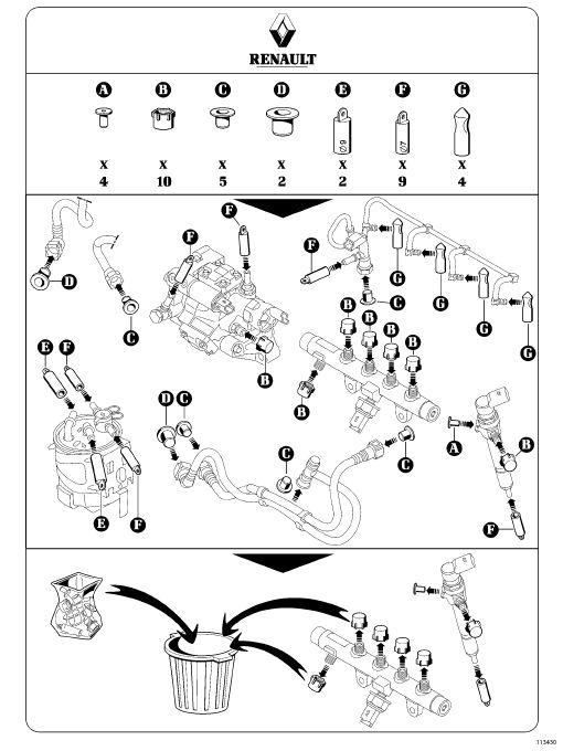
10A-9 ENGINE AND LOWER ENGINE ASSEMBLY Engine: Precautions
10A Part no. 77 01 476 857 113430
for repair
ENGINE AND LOWER ENGINE ASSEMBLY
Engine: Precautions for repair
10A-10
10A
ENGINE AND LOWER ENGINE ASSEMBLY
Engine:
Precautions for repair
K9K, and 260 or 270 or 272 or 700 or 702 or 704 or 706 or 710 or 712 or 714 or 716 or 718 or 722 or 724 or 728 or 729 or 750 or 752 or 760 or 762 or 766 or 768 or 790
10A-11
10A
10A-12 ENGINE AND LOWER ENGINE ASSEMBLY Engine:
10A Part no. 77 01 206 804 20977
Precautions for repair
ENGINE AND LOWER ENGINE ASSEMBLY
Engine: Precautions for repair
5 - Engine cleaning
Protect the various accessories to prevent water and cleaning products splashing on them. Do not allow water to enter the inlet pipes.
6 - Cleaning the engine
WARNING
parts
When cleaning parts, it is essential to not knock the parts against each other, or their mating faces may be damaged and therefore their adjustments may be altered, which could damage the engine.
7 - Fitting relieved threads
The tapped holes of all parts including the engine (except the rocker cover) may be repaired using the offset thread repair kit
10A-13
10A
- The camshaft pulley nut
- The tensioning rollers and pulleys for the accessories and timing belts
- The bolts for the accessories belt mechanical tensioning roller - The accessories and timing belts - The crankshaft accessories pulley bolt - The cooling circuit hoses if they are damaged - The thermostat - The turbocharger plastic pipes.
II - CONSUMABLES
10A-14
AND LOWER ENGINE
10A
ENGINE
ASSEMBLY Engine: Parts and consumables for the repair work
I - PARTS ALWAYS TO BE REPLACED AFTER REPAIRING THE ENGINE - All seals - The oil filter - The copper washers on the injector holders, - The high pressure injection pipes, - The pipe plugs, - The valve guides - The valve stem seals - The cooling jets at the bottom of the piston - The engine flywheel bolts - The crankshaft bearing cap bolts - The con rod cap bolts
SILICONE
SEAL BeadCrankshaft
HIGH STRENGTH THREADLOCK 1
dropsCoolant
CoatThe
CLEANING
-Injection
BLANKING PLUGS -Injection
DELPHI
SET OF BLANKING PLUGS -Injection
SIEMENS
CLEANING PRODUCT CoatInjection
77
CLEANER CoatInjection
GREY
PAD -The
TypeQuantityComponent concernedPart no. DÉCAPJOINT CoatThe joint faces 77 01 405 952
ADHESIVE
bearing cap no. 1 Cylinder block-sump connection 77 11 227 484 LOCTITE 518 Bead Camshaft bearing caps no. 1 and no. 6 77 01 421 162 "VARYBOND 12-71"
- 2
pump bolts 77 11 230 112 DEGREASER
joint faces 77 11 224 559
CLOTHS
circuit 77 11 211 707 SET OF
system
77 01 206 804
system
77 01 476 857 INJECTOR
system
11 224 188 BRAKE
system 77 11 226 128
SCUFF
joint faces 77 01 405 943
ENGINE AND LOWER ENGINE ASSEMBLY
Upper engine: Tightening torque
UPPER ENGINE
10A-15
10A
ENGINE AND LOWER ENGINE ASSEMBLY
Upper engine: Tightening torque
10A-16
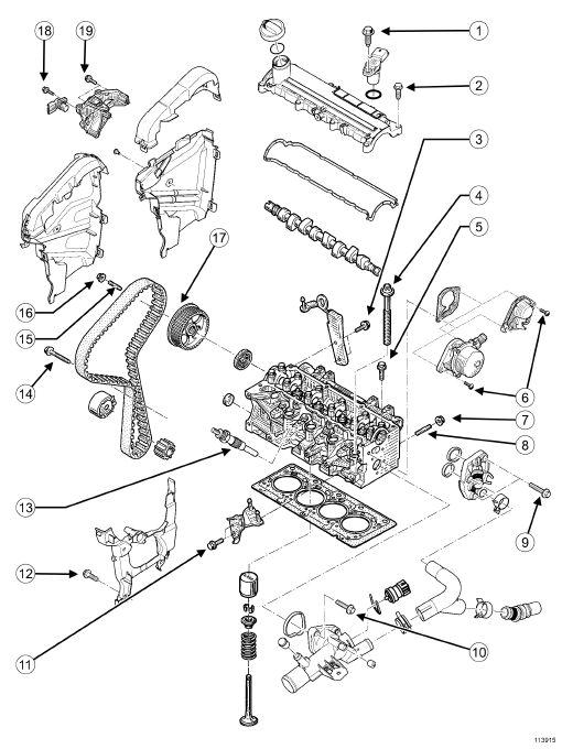
10A 113915
(1 )
ENGINE AND LOWER ENGINE ASSEMBLY
Upper engine: Tightening torque
Tightening
torques in Nm and/or in degrees
cylinder marking sensor bolt 8 ± ± ± ± 0.8
(2 ) Rocker cover bolts 12 ± ± ± ± 1.2
(3 )
Lifting eye bolts (timing end) Bolt H M8x125-16 21 ± ± 2.1 Bolt H M6x100-23 10 ± ± ± ± 1
(4 )
Cylinder head bolts 25 ± ± 2.5 + 255˚± ± 10˚
(5 ) Camshaft bearing cap bolts 11 ± ± ± ± 1.1
(6 ) Vacuum pump bolt 21 ± ± ± ± 2.1
(7 ) Exhaust manifold nut 26 ± ± ± ± 2.6
(8 ) Exhaust manifold stud 8 ± ± 0.8
(9 ) EGR cooler cover bolt 12 ± ± ± ± 1.2
(10) Cylinder head coolant pipe housing outlet bolt 11 ± ± ± ± 1.1
(11) Engine lifting eye bolts (flywheel end) 13 ± ± ± ± 1.3
(12) Inner timing cover bolt 9 ± ± 0.9
(13) Heater plug 15 ± ± 1.5
(14) Timing tension wheel bolt 27 ± ± ± ± 2.7
(15) Camshaft pulley stud 10 ± ± ± ± 1 at 14 ± ± ± ± 1.4
(16) Camshaft pulley nut 30 ± ± ± ± 3 + 86˚± ± ± ± 6˚
(17) Camshaft pulley ring gear bolt 14 ± ± 1.4
(18) Cylinder marking sensor bolt 8 ± ± ± ± 0.8
(19) Cylinder head suspended mounting bolt 25 ± ± ± ± 2.5
10A-17
10A
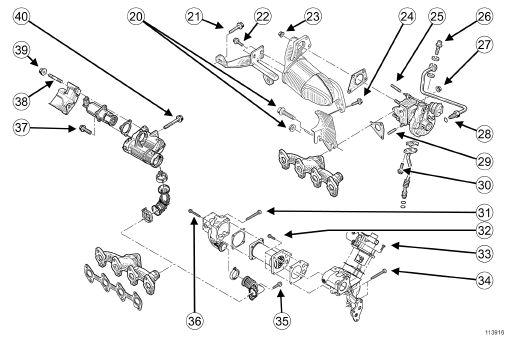
(20)
(21)
(22)
ENGINE AND LOWER ENGINE ASSEMBLY
Upper engine: Tightening torque
Couple de serrage en N.m et / ou degrés
Downstream catalytic converter stay nut and bolt (gearbox side) 21 ± ± 2.1
Upstream catalytic converter stay bolt (engine side) 44 ± ± ± ± 4.4
Upstream stay bolt on the catalytic converter 26 ± ± ± ± 2.6
(23) Catalytic converter-turbocharger nut 26 ± ± ± ± 2.6
(24) Downstream stay bolt on the catalytic converter 21 ± ± 2.1
(25)
(26)
(27)
(28)
Turbocharger stud 9 ± ± ± ± 0.9
Turbocharger oil supply pipe bolt on the turbocharger. 23 ± ± ± ± 2.3
Turbocharger nut on the manifold 26 ± ± ± ± 2.6
Turbocharger oil supply pipe bolt on the cylinder head
Collar nut to 35 ± ± 3.5 (without high strength threadlock)
Collarless nuts to 23 ± 2.3 (with high strength threadlock)
(29)
stud
± ± 0.9
10A-18
10A 113916
Turbocharger
9 ± ±
Renault Kxx And K9k Engine Workshop Repair Manual Full download: http://manualplace.com/download/renault-kxx-and-k9k-engine-workshop-repair-manual/