Types S208 and S209 Table 4. Outlet Pressure Range Data CONTROL SPRING TYPE NUMBER
S208, S209
S208H, S209H
S208P1, P2, P3, S209P1, P2, P3
OUTLET PRESSURE RANGE
Part Number
Free length Inches (cm)
3.5 to 6.5 in. w.c. (9 to 16 mbar) 5 to 9 in. w.c. (13 to 23 mbar) 8.5 to 18 min. w.c. (21 to 45 mbar) 14 to 30 in. w.c. (35 to 75 mbar)
1D892627022 1D892727012 1D893227032 1D893327032
7-1/2 (19) 7-7/8 (20) 7-1/2 (19) 7-1/4 (18.4)
.120 (.030) .130 (.033) .156 (.039) .182 (.046)
Red Black Gray Dk. green
1 to 2 psig (70 to 140 mbar) 1-1/2 to 3-1/4 psig (105 to 225 mbar) 2 to 5 psig (140 to 345 mbar) 3.5 to 6.5 in. w.c. (9 to 16 mbar) 5 to 9 in. w.c. (13 to 23 mbar) 8.5 to 18 min. w.c. (21 to 45 mbar) 14 to 30 in. w.c. (35 to 75 mbar) 1 to 2 psig (70 to 140 mbar) 1-1/2 to 3-1/4 psig (105 to 225 mbar)
1H975827032 1H975927032 1P615427142 1D892627022 1D892727012 1D893227032 1D893327032 1H975827032 1H975927032
7-3/8 (18.7) 7-3/8 (18.7) 6-1/2 (16.5) 7-1/2 (19) 7-7/8 (20) 7-1/2 (19) 7-1/4 (18.4) 7-3/8 (18.7) 7-3/8 (18.7)
.225 (.057) .250 (.063) .283 (.072) .120 (.030) .130 (.033) .156 (.039) .182 (.046) .225 (.057) .250 (.063)
Dk. blue Orange Yellow Red Black Gray Dk. green Dk. blue Orange
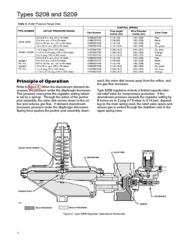
Principle of Operation Refer to figure 2. When the downstream demand decreases, the pressure under the diaphragm increases. This pressure overcomes the regulator setting (which is set by a spring). Through the action of the pusher post assembly, the valve disk moves closer to the orifice and reduces gas flow. If demand downstream increases, pressure under the diaphragm decreases. Spring force pushes the pusher post assembly down-
Wire Diameter Inches (cm)
Color Code
ward, the valve disk moves away from the orifice, and the gas flow increases. Type S209 regulators include a limited capacity internal relief valve for overpressure protection. If the downstream pressure exceeds the regulator setting by 8 inches wc to 2 psig (17.5 mbar to 0.14 bar), depending on the main spring used, the relief valve opens and excess gas is vented through the stabilizer vent in the upper spring case.
RELIEF VALVE SPRING VALVE DISK DIAPHRAGM
PUSHER POST VSX MODULE B2507
ORIFICE INLET PRESSURE
OUTLET PRESSURE
Figure 2. Type S209 Regulator Operational Schematic
4