Instruction Manual
DVC6200f Digital Valve Controller November 2011
D103412X012
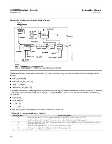
Figure 4‐24. Analog Input Function Block Schematic ANALOG MEASUREMENT ALARM_TYPE
ACCESS ANALOG MEAS.
CHANNEL
HI_HI_LIM HI_LIM LO_LO_LIM LO_LIM
ALARM DETECTION
OUT_D
ALARM_HYS LOW_CUT
SIMULATE
L_TYPE FIELD_VAL
PV
FILTER
PV_FTIME IO_OPTS
STATUS CALC.
OUT
MODE
FIELDBUS‐FBUS_02A
CUTOFF
CONVERT
STATUS_OPTS
OUT_SCALE XD_SCALE NOTES: OUT_D = BLOCK OUTPUT VALUE AND STATUS OUT_D = DISCRETE OUTPUT THAT SIGNALS A SELECTED ALARM CONDITION.
Process Alarm detection is based on the OUT [8] value. You can configure the alarm limits of the following standard alarms: High (HI_LIM [28]) High high (HI_HI_LIM [26]) Low (LO_LIM [30]) Low low (LO_LO_LIM [32]) In order to avoid alarm chattering when the variable is oscillating around the alarm limit, an alarm hysteresis in percent of the PV [7] span can be set using the ALARM_HYS [24] parameter. The priority of each alarm is set in the following parameters: HI_PRI [27] HI_HI_PRI [25] LO_PRI [29] LO_LO_PRI [31] Alarms are grouped into five levels of priority, as shown in table 4‐53. Table 4‐53. AI Function Block Alarm Priorities Priority Description(1)
Priority Number 0
The priority of an alarm condition changes to 0 after the condition that caused the alarm is corrected.
1
An alarm condition with a priority of 1 is recognized by the system, but is not reported to the operator.
2
An alarm condition with a priority of 2 is reported to the operator, but generally does not require operator attention (such as diagnostics and system alerts).
3-7
Alarm conditions of priority 3 to 7 are advisory alarms of increasing priority.
8-15
Alarm conditions of priority 8 to 15 are critical alarms of increasing priority.
1. The priority classes “advise” and “critical” have no relationship to PlantWeb Alerts.
176