Product Bulletin 62.1:DVC6000 SIS December 2010
DVC6000 SIS
Additional System Components: Specifications, Requirements, and Functionality LCP100 Local Control Panel (continued) Push buttons: Protected with lockable covers Dimensions: 253.1 mm (10 inches) long by 109.5 mm (4.3 inches) wide by 127.8 mm (5 inches) deep. See figure 21. Approximate Weight: 2.2 kg (4.9 lbs) Lights Green: Solid when the valve is at its normal operating position, and loop current is normal. Flashing when the valve is not at its normal operating position, and loop current is normal. Red: Solid when the valve is at its Fail Safe State and loop current is tripped. Flashing when valve is not at its Fail Safe State and loop current is tripped.
Amber (Ready−to−Reset): Solid when the valve is latched in the trip position, and loop current is normal. Buttons Green: SAfter an emergency demand— commands the valve to its normal position only after control current is restored (manual reset). SDuring a test— abort test Red: Always commands the valve to its Fail Safe State regardless of the control current. Black: Press and hold for 3 to 10 seconds. Commands the configured partial stroke test. Can be overridden by the Close button, Open button, or Emergency Demand. SDuring a test— abort test
1. The line conditioner requires no power to operate; its input requirements are driven entirely by its output load requirements. 2. The pressure/temperature limits in this document and any other applicable code or standard should not be exceeded. 3. The use of external piloting requires the pilot pressure to be at least 15 psig higher than the main line pressure. 4. ASCO EFX8553G305 103594 or EFX8551G305 103594 low−powered 24VDC solenoid valves with aluminum bodies can be used where the application requires zero differential pressure and when the solenoid valve exhaust port is connected to another solenoid valve used as a selector or diverter. 5. Contact your Emerson Process Management sales office for the status of pending agency approvals.
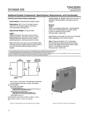
LINE CONDITIONER
INPUT VOLTAGE
SOLENOID VALVE
LOAD VOLTAGE
DVC6000 SIS DIGITAL VALVE CONTROLLER
S
LOAD CURRENT
INPUT VOLTAGE = LOAD VOLTAGE + LINE CONDITIONER VOLTAGE DROP LINE CONDITIONER VOLTAGE DROP = 30 OHMS x LOAD CURRENT CALCULATION EXAMPLE: CALCULATING LOAD CURRENT FOR THE SOLENOID VALVE, ASSUME REQUIRES MINIMUM 42 mA AT 22 VOLTS DC TO PULL−IN (FROM SOLENOID VALVE SPECIFICATIONS) FOR THE DIGITAL VALVE CONTROLLER, WHEN OPERATING IN MULTI−DROP, REQUIRES 8 mA (FROM DIGITAL VALVE CONTROLLER SPECIFICATIONS)
W8302
LOAD CURRENT=42+8=50 mA LINE CONDITIONER VOLTAGE DROP= 30 OHMS x .050 AMPS = 1.5 VOLTS INPUT VOLTAGE = 22 VOLTS + 1.5 VOLTS = 23.5 VOLTS DC E0853
Figure 19. Determining Line Conditioner Input Voltage
26
Figure 20. Fisher LC340 Line Conditioner