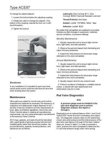
Type ACE97 To change the depad setpoint: 1. Loosen the locknut below the adjusting coupling. 2. Rotate the collar to change the setpoint. (The bottom of the coupling—nearest the lock nut—is lefthand threaded.) 3. Tighten the locknut.
ADJUSTING SCREW
Lubricants: Dow Corning #111, Dow Corning #3452 Chemical Resistant Lubricant Thread Protector: Anti-Seize Sealant: Loctite PST #592, Teflon Tape Adhesive: Loctite #222 Be certain that nameplates are updated to accurately indicate any field changes in equipment, materials, service conditions, or pressure settings.
Monthly Maintenance 1. Visually inspect the unit to ensure tight connections, tight seals, and safe operation.
LOCK NUT
2. Observe the pad and depad (tank blanketing and vapor recovery) pressures. 3. Inspect the inlet pressure for the proper range (stamped on the valve nameplate).
Annual Maintenance 1. Visually inspect the unit to ensure tight connections, tight seals, and safe operation. 2. Observe the pad and depad (tank blanketing and vapor recovery) pressures. E0679
Figure 7. Changing the Pad Setpoint
Shutdown In any installation it is important to open and close valves slowly and to close the inlet shut-off valve first when shutting down the system.
Maintenance Valve parts are subject to normal wear and must be inspected and replaced as necessary. The frequency of inspection and replacement of parts depends on the severity of service conditions and the requirements of local, state, and federal regulations. Due to the care Fisher Controls takes in meeting all manufacturing requirements, use only replacement parts manufactured or furnished by Fisher Controls. All O-rings, gaskets, and seals should be lubricated with a good grade of general purpose lubricant and installed gently rather than forced into position. Approved lubricants, sealants, thread protectors, and adhesives are as follows:
8
3. Inspect the inlet pressure for the proper range (stamped on the valve nameplate). 4. Visually inspect valve for any external wear. 5. If there is evidence of leakage or unstable internal motion, a rebuild with seal replacement and relubrication may be in order.
Pad Valve Diagnostics Note A pressure gauge must be installed in the pad valve diagnostic port to perform diagnostic analysis. See figures 2 through 4. Diagnostics are an optional feature of the 1 and 2-inch Type ACE97 valves and aid in evaluating valve operation. The diagnostic analysis relies on the relationship of pad valve pilot pressure and the inlet pressure of the pad valve (see figures 2 through 4).The basic relationships are shown in table 2. In order to evaluate a valve, examine the valve nameplate to determine the Cv and inlet pressure range (main valve spring).