Type 8532 Table 6. Torque Values for Fasteners FASTENER NOMINAL SIZE #10 Retaining Ring Screws
1/4
5/16
3/8
7/16
1/2
9/16
Pounds-inch 41
100
220
3/4
7/8
1
1-1/8
Pounds-Foot 400
53
83
119
166
296
480
720
1000
225
401
651
976
1356
NewtonSmeters 4.6
11
25
45
72
112
161
Pounds-inch G Gasket Retaining Bolts
5/8
35
81
167
Pounds-Foot 295
39
59
86
119
210
330
480
617
161
286
447
651
837
NewtonSmeters 4.0
9.2
19
33
53
80
117
Nore: These values are based upon standard materials, S66286/Inconel screws and ASTM A193GRB6 bolts. For other special fasterer materials, please contact your Fisher Controls sales office or sales representative.
3. Carefully tuck the O-ring downward into the body T-slot until the seal ring is completely entrapped in the body T-slot, and it completely covers the backup Oring. 4. Re-install the retaining ring and the socket head cap screws. Tighten the cap screws just enough to eliminate any movement of the retaining ring. Do not over-tighten the retaining ring screws. Using a bluntend tool, carefully tuck the lip of the seal ring under the retaining ring. 5. When the seal is under the lip of the retaining ring, continue to tighten the cap screws according to standard procedures. Do not fully torque screws at this time. Final tightening of screws is accomplished in step 7 of this procedure. A5251-1*/IL
6. Manually rotate the upper shaft clockwise 180 degrees to return the disk (key 2) to its closed position. 7. The final seating of the retaining ring cap screws can now be done. For the screw torque values, refer to table 6. The seal is now fully installed. Refer to the Installation procedures in this manual.
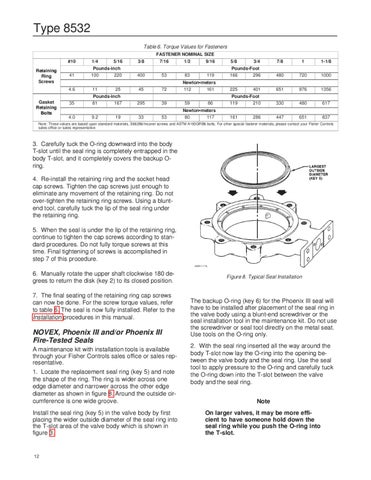
NOVEX, Phoenix III and/or Phoenix III Fire-Tested Seals A maintenance kit with installation tools is available through your Fisher Controls sales office or sales representative. 1. Locate the replacement seal ring (key 5) and note the shape of the ring. The ring is wider across one edge diameter and narrower across the other edge diameter as shown in figure 8. Around the outside circumference is one wide groove. Install the seal ring (key 5) in the valve body by first placing the wider outside diameter of the seal ring into the T-slot area of the valve body which is shown in figure 3.
12
Figure 8. Typical Seal Installation
The backup O-ring (key 6) for the Phoenix III seal will have to be installed after placement of the seal ring in the valve body using a blunt-end screwdriver or the seal installation tool in the maintenance kit. Do not use the screwdriver or seal tool directly on the metal seat. Use tools on the O-ring only. 2. With the seal ring inserted all the way around the body T-slot now lay the O-ring into the opening between the valve body and the seal ring. Use the seal tool to apply pressure to the O-ring and carefully tuck the O-ring down into the T-slot between the valve body and the seal ring. Note On larger valves, it may be more efficient to have someone hold down the seal ring while you push the O-ring into the T-slot.