4200 Series
43
8
39A6195-C / DOC
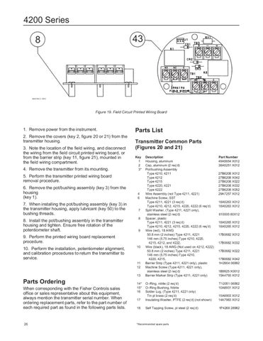
Figure 19. Field Circuit Printed Wiring Board
1. Remove power from the instrument. 2. Remove the covers (key 2, figure 20 or 21) from the transmitter housing. 3. Note the location of the field wiring, and disconnect the wiring from the field circuit printed wiring board, or from the barrier strip (key 11, figure 21), mounted in the field wiring compartment. 4. Remove the transmitter from its mounting.
Parts List Transmitter Common Parts (Figures 20 and 21) Key 1 2 3*
5. Perform the transmitter printed wiring board removal procedure. 6. Remove the pot/bushing assembly (key 3) from the housing (key 1). 7. When installing the pot/bushing assembly (key 3) in the transmitter housing, apply lubricant (key 50) to the bushing threads. 8. Install the pot/bushing assembly in the transmitter housing and tighten. Ensure free rotation of the potentiometer shaft.
4 6
7 8
9
9. Perform the printed wiring board replacement procedure. 10. Perform the installation, potentiometer alignment, and calibration procedures to return the transmitter to service.
10
11 12 13
Parts Ordering When corresponding with the Fisher Controls sales office or sales representative about this equipment, always mention the transmitter serial number. When ordering replacement parts, refer to the part number of each required part as found in the following parts lists.
26
14* 15* 16
Description Housing, aluminum Cap, aluminum (2 req’d) Pot/bushing Assembly Type 4210, 4211 Type 4212 Type 4215 Type 4220, 4221 Type 4222 Wire Assembly (not Type 4211, 4221) Machine Screw, SST Type 4211, 4221 (3 req’d) Type 4210, 4212, 4215, 4220, 4222 (6 req’d) Split Washer, (Type 4211, 4221 only), stainless steel (2 req’d) Spacer, plastic Type 4211, 4221 (3 req’d) Type 4210, 4212, 4215, 4220, 4222 (6 req’d) Wire (red), 18 AWG 50.8 mm (2 inches) Type 4211, 4221 146 mm (5.75 inches) Type 4210, 4220, 4215, 4212, and 4222, Wire (black), 18 AWG (Not used on 4212, 4222) 50.8 mm (2 inches) Type 4211, 4221 146 mm (5.75 inches) Type 4210, 4220, 4215, Barrier Strip (Type 4211, 4221 only), plastic Machine Screw (Type 4211, 4221 only), stainless steel (2 req’d) Barrier Marker Strip (Type 4211, 4221 only)
Part Number 49A5654 X012 38A5251 X012 27B6208 X012 27B6208 X042 27B6208 X022 27B6208 X032 27B6208 X052 29A7257 X012 18A5263 X012 18A5263 X012 610005 80X12 18A5265 X012 18A5265 X012 17B0682 X012 17B0682 X032 17B0682 X022 17B0682 X042 1H2904 06992 1B9925 X0012 15A4793 X012
17
O–Ring, nitrile (2 req’d) O–Ring Bushing, Nitrile Solder Lug, (Type 4211, 4221 only) Tin pl brass (2 req’d) Insulating Washer, PTFE (2 req’d) (not shown)
15A6903 X012 14A7983 X012
18
Self Tapping Screw, pl steel (2 req’d)
1P4269 28982
*Recommended spare parts
T12051 06562 10A8931 X012