4195KA, KB, and KC Series 14. Perform the controller calibration procedures and, if necessary, the appropriate remote set point calibration procedure in section 3 or 4.
TRAVEL STOP NUT
Replacing Capsular Element Controller Link 5 1. Remove the two screws (key 6), and lift off the proportional band indicator cover (key 36). 2. Note the location of the connection holes and disconnect both ends of link 5 (key 88) from the lever arms of the two pivot assemblies. Refer to figure 5–22 for parts locations.
DIAPHRAGM ASSEMBLY EXTENSION
DRIVE BRACKET
3. Loosen the adjustment screw on the replacement link and adjust the length to match the original link. Tighten the adjustment screw. 4. Attach the replacement link to the two lever arms in the same holes noted in step 2. 5. Move the set point indicator, either manually or with remote set point pressure, to the mid-scale mark on the process scale and set the proportional band between DIRECT and REVERSE.
DRIVE FLEXURE
GUIDE FLEXURE
6. The process pointer should be aligned with the pointer subassembly as shown in figure 5–15. If not, loosen the zero adjustment locking screw and adjust the process pointer zero adjustment to align the process pointer and pointer subassembly. Tighten the zero adjustment locking screw. 7. Apply process pressure equal to the mid-scale value of the process scale span. The process pointer should indicate the mid-scale ±3 percent of the scale span. If not, loosen the screw in link 1 or link 5, and move the process pointer to the mid-scale mark of the process scale span. Tighten the screw.
TRAVEL STOP NUT
TRAVEL STOP
A
A
LONG PIVOT LINK 5
LINK 1
8. Perform the controller calibration procedures and, if necessary, the appropriate remote set point calibration procedure in section 3 or 4.
SHORT PIVOT
LINEARITY ADJUSTMENT
Capsular Element Controller Maintenance Calibration Precalibration Procedure 1. Remove the two machine screws (key 6) and lift off the proportional band indicator cover (key 36). 2. Set the proportional band adjustment between DIRECT and REVERSE. 3. Remove the two screws (key 103) and remove the tie bar (key 97) from the capsular element assembly. Aligning the Drive Bracket Assembly Refer to figures 5–22 and 5–28. 1. With an Allen wrench, Loosen the set screw in the hex nut of the drive bracket assembly (key 84).
58A0708-E A6946 / IL
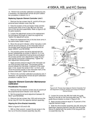
Figure 5–22. Process Input Capsular Element Assembly Part and Adjustment Locations (Positive and Compound Pressure Element Shown)
2. Loosen the screw (key 98) that holds the guide flexure to the tab on the mounting plate (key 77). The guide flexure location is shown in figure 5–22. 3. Apply process pressure equal to 75 percent of the capsular element range. 4. Slide the drive bracket assembly (key 84) along the diaphragm capsule extension (key 82) until the guide flexure is aligned with the center of the long pivot clevis assembly (key 78).
5–27