Model 275 HART Communicator Use the Increase and Decrease selections until the displayed press matches the target.
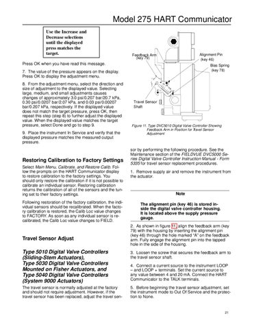
Alignment Pin (key 46)
Feedback Arm (key 79)
Press OK when you have read this message.
Bias Spring (key 78)
7. The value of the pressure appears on the display. Press OK to display the adjustment menu. 8. From the adjustment menu, select the direction and size of adjustment to the displayed value. Selecting large, medium, and small adjustments causes changes of approximately 3.0 psi/0.207 bar/20.7 kPa, 0.30 psi/0.0207 bar/2.07 kPa, and 0.03 psi/0.00207 bar/0.207 kPa, respectively. If the displayed value does not match the target pressure, press OK, then repeat this step (step 8) to further adjust the displayed value. When the displayed value matches the target pressure, select Done and go to step 9. 9. Place the instrument In Service and verify that the displayed pressure matches the measured output pressure.
Restoring Calibration to Factory Settings Select Main Menu, Calibrate, and Restore Calib. Follow the prompts on the HART Communicator display to restore calibration to the factory settings. You should only restore the calibration if it is not possible to calibrate an individual sensor. Restoring calibration returns the calibration of all of the sensors and the tuning set to their factory settings. Following restoration of the factory calibration, the individual sensors should be recalibrated. When the factory calibration is restored, the Calib Loc value changes to FACTORY. As soon as any individual sensor is recalibrated, the Calib Loc value changes to FIELD.
Travel Sensor Adjust
.75 B
1A 1.5 2
Travel Sensor Shaft
Figure 11. Type DVC5010 Digital Valve Controller Showing Feedback Arm in Position for Travel Sensor Adjustment
sor by performing the following procedure. See the Maintenance section of the FIELDVUE DVC5000 Series Digital Valve Controller Instruction Manual - Form 5335 for travel sensor replacement procedures. 1. Remove supply air and remove the instrument from the actuator.
Note The alignment pin (key 46) is stored inside the digital valve controller housing. It is located above the supply pressure gauge. 2. As shown in figure 11, align the feedback arm (key 79) with the housing by inserting the alignment pin (key 46) through the hole marked “A” on the feedback arm. Fully engage the alignment pin into the tapped hole in the side of the housing.
Type 5010 Digital Valve Controllers (Sliding-Stem Actuators), Type 5030 Digital Valve Controllers Mounted on Fisher Actuators, and Type 5040 Digital Valve Controllers (System 9000 Actuators)
3. Loosen the screw that secures the feedback arm to the travel sensor shaft.
The travel sensor is normally adjusted at the factory and should not require adjustment. However, if the travel sensor has been replaced, adjust the travel sen-
5. Before beginning the travel sensor adjustment, set the instrument mode to Out Of Service and the protection to None.
4. Connect a current source to the instrument LOOP – and LOOP + terminals. Set the current source to any value between 4 and 20 mA. Connect the HART Communicator to the TALK terminals.
21