Type 2100 and 2100E Installation Installation Procedures The installation procedures include those common to both the Type 2100 pneumatic and Type 2100E electric liquid level switches and additional ones for each switch.
Common Procedures for Either Switch The horizontal line forged on the displacer cage indicates the approximate switching point (figures 1 and 2). When you mount the Type 2100 or Type 2100E switch, position it so that the horizontal line corresponds to the horizontal level at which switching is desired. Before you install the Type 2100 or Type 2100E switch, remove the plastic plugs from the process connections. One of these plugs retains a paper tube that protects the displacer and torque tube during handling and shipping. This paper tube must also be removed. There are two process connections, one at the top and one at the bottom of the cage. To mount the switch, connect the appropriate top and bottom process connections to the vessel using the required size pipe. The pipe must be capable of supporting the assembly and of withstanding the pressure involved. Use accepted piping and welding practices when making connections. Install isolating valves between the vessel and cage. Plugs are furnished for the unused process connections. However, one of the plugs can be removed, and a bleed valve or drain can be installed in one of the unused connections.
A3619-1/IL
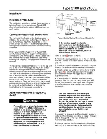
Figure 3. Detail of Optional Street Tee and Bleed Orifice
If the existing supply medium is corrosive, make sure the tubing and instrument components that contact the corrosive medium are suitable corrosion-resistant materials, or use a noncorrosive medium. Refer to figure 5 except as noted. 1. Connect a supply pressure line to the 1/4-inch (6.4 mm) NPT female connection located in the back plate (key 10). 2. Install an output line between the supply pressure line and the equipment to be operated by the switch. 3. Install a street tee and bleed orifice (keys 34 and 35, figure 3) or other fixed restriction in the supply pressure line between the supply source and the output signal line. 4. If a remote vent is required, remove the vent assembly (key 23) from the 1/4-inch (6.4 mm) NPT female vent connection and install a vent line to an area where the operating medium can be safely exhausted. Note
Additional Procedures for Type 2100 Switch
WARNING Personal injury or property damage may occur if the Type 2100 switch supply medium is not clean, dry, noncorrosive air or gas. If a clean, noncorrosive medium is not used, the switch may become inoperative and allow the level in a process vessel to exceed safe limits. Install a 40 micron filter and suitable equipment to dry the supply medium and establish a maintenance cycle to check the filter and equipment.
The vent line should have as large a diameter as possible with a minimum number of bends and elbows. The vent line should be as short as possible. Protect the end of the vent pipe from the entrance of rain, snow, insects, or any other foreign material that may plug the vent line. Inspect the vent line opening periodically to ensure that it is not plugged. If necessary to change to a different supply pressure, install a different nozzle according to steps 1 through 4 and 15 through 18 of the Type 2100 switch maintenance procedure. To change switch action from low-level to high-level switching or vice versa, reverse the positions of the
3