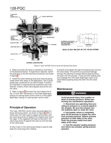
128-PQC 1/4-INCH NPT VENT CONNECTION
TRAVEL INDICATOR
1/4-INCH NPT INPUT SIGNAL CONNECTION
PACKING BOX
LEAK-OFF VENT PACKING 14A9142-C/DOC
CAGE AND SEAT
VALVE PLUG
W5750-1*/IL
Figure 3. Type 128-PQC Control Valve with Spring-Close Action
3. Make sure that the valve is oriented so that flow is in the desired direction. If angle flow is desired, switch the pipe plug to the left-hand end connection as shown in figure 3. 4. Install the valve following local and national piping codes when they apply to the application. Use a good grade pipe compound on all male threads. If continuous operation is required during inspection and maintenance, install a three-valve bypass around the control valve. 5. Refer to figure 3. Connect the input signal line to the 1/4-inch NPT connection in the lower diaphragm casing of a spring-close control valve or in the upper diaphragm casing of a spring-open control valve.
Principle of Operation The Type 128-PQC control valve has push-down-toclose valve plug action, as shown in figure 3. With a metal seat, the valve uses a caged construction and the valve plug shuts off against the integral seat ring in the cage. In the cageless soft-seat construction, the valve plug shuts off against the seat cut into the web of the valve body. A nylon insert in the valve plug thread is used to help keep the valve plug from rotating.
4
A leakoff vent passes through the packing box and out the valve body. This permits any process leakage through the packing to escape before passing along the stem into the actuator. It also permits loading pressure leakage from the lower diaphragm case to escape before passing along the stem into the valve body.
Maintenance WARNING Avoid personal injury from sudden release of process pressure. Before performing any maintenance operations: Disconnect any operating lines providing air pressure or a control signal to the actuator. Be sure the actuator cannot suddenly open or close the valve. Use bypass valves or completely shut off the process to isolate the valve from process pressure. Relieve process pressure on both sides of the valve. Drain the process media from both sides of the valve. Vent the actuator loading pressure and relieve any actuator spring precompression.