Types 1051 & 1052 with F & G Mounting VALVE SERIES OR DESIGN MOUNTING
ACTION(1)
Right-Hand
PDTC PDTO
BALL/PLUG ROTATION TO CLOSE CCW CCW
Left-Hand
PDTC PDTO
Left-Hand (Optional)(2)
PDTC PDTO
VALVE SERIES OR DESIGN
V250
V150 V200 & V300 V150,
CV500 V500
A B
A B
A B
DISK/BALL ROTATION TO CLOSE CW CW
NA NA
8510B, 8532, 8560 & 9500 B A
CCW CCW
NA NA
D C
D C
CW CW
C D
C D
CW CW
NA NA
C D
NA NA
NA NA
NA NA
NA NA
V250
1. PDTC—Push-down-to-close, and PDTO—Push-down-to-open. 2. A left hand ball will be required for the 3- through 12-inch Series B and the 14- to 20-inch, with or without attenuator.
STYLE A
STYLE B
POSITION 1
1
POSITION 1
1
STYLE D FLOW STYLE C
4
2 LEFT-HAND MOUNTING
4
2 3
3
RIGHTĆHAND MOUNTING STYLE C
STYLE D STYLE B
STYLE A
POSITION 1
POSITION 1
1
1
FLOW 2
4
4
2 3
43A6505-A A1584-3
RIGHT-HAND MOUNTING
3
LEFTĆHAND MOUNTING NOTES: 1 POSITION 1 IS STANDARD; POSITIONS 2 THROUGH 4 (SHOWN IN DOTTED LINES) ARE ALTERNATIVES.
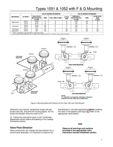
Figure 3. Mounting Styles and Positions for the Type 1051 and 1052 Actuator
obtained in this manner, temporarily loosen the cap screws (key 23), and shift the housing slightly. Do not stroke the actuator while the cover is off.
flow direction in all valve applications before installing the valve in the pipeline (see figure 4). Refer to the appropriate valve bulletin.
16. Follow the instructions given in the Turnbuckle Adjustment section before proceeding to the Loading Connection section. Note
Valve Flow Direction Valve construction can change the flow direction for a control valve assembly. It is important to observe the
Observe all warnings and cautions provided in the appropriate valve instruction manual Installation section.
5