2-ABB - Switchboards n panelboards

Page 1

ABB
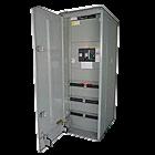
Group Mounted ReliaGear SB Switchboard 3 4 ReliaGear SB Switchboard EV Grid-to-Charger Generator Connection 29 46 GenTower Generator Connection 47 2 Individually Mounted Power Break II Switchboard 52 53 PANELBOARDS 76 PROTECTION, DISTRIBUTION & CONTROL Metering Commercial Metering 70 71 1
Index SWITCHBOARDS

PROTECTION, DISTRIBUTION & CONTROL

1
2
SWITCHBOARDS
3
GROUP MOUNTED

ReliaGear SB Switchboard

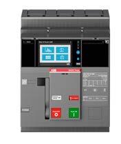
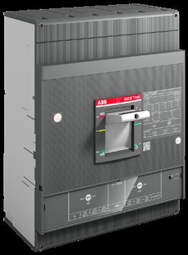
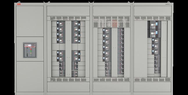
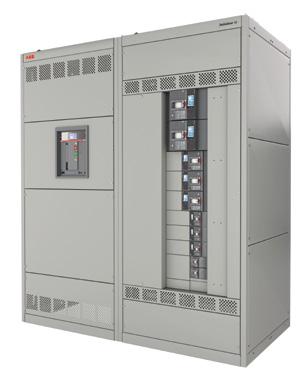
ReliaGear® SB switchboards feature a safer, more reliable design and groundbreaking SACE® Emax 2 power circuit breakers or SACE® Tmax® XT plug-in MCCBs to save time, labor, and cost while helping ensure greater energy efficiencyandreliability.

ReliaGear SB switchboards are available up to 6,000 A and 600 VAC. Plug-in group mounted distribution sections allow for devices, such as circuit breakers, to be installed anywhereonthebusstack.

ReliaGear SB switchboard is a safer, smarter, and more sustainablesolutionforprojectsofanysize–with2newfast shippingoptionsavailable.

4

DESCRIPTIVE BULLETIN

The road to reliability

ReliaGear ® SB Switchboards
5
6
3 TABLE OF CONTENTS —
of contents 04 The road to reliability 06 – 07 Install components in seconds 09 More advantages 10 – 13 Sw itchboard details 14 Power circuit breakers 15 Molded case circuit breakers 16 – 17 Ekip trip units 18 – 20 Fast shipping options 21 Catalog numbers 7
Table

The road to reliability

ReliaGear ® SB Switchboards

Ready to dramatically speed up field modifications and eliminate labor-intensive bolt-on components? Plug into what’s next in switchboards: ReliaGear SB.

01

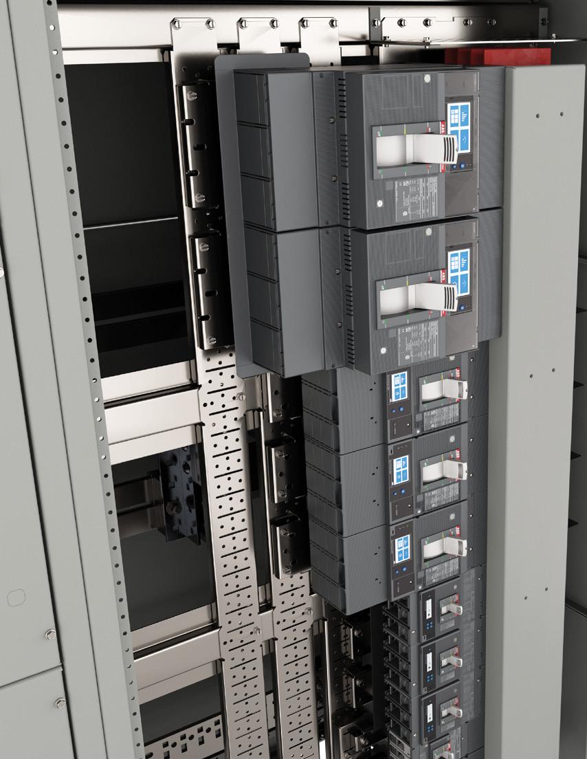
ReliaGear SB features a safe, reliable design that dramatically saves time, labor and cost while helping to ensure greater energy efficiency and reliability.
4 RELIAGEAR ® SB SWITCHBOARDS
One-sided configurations available to minimize the width 01 —
8
9

— Install components in seconds

Safe. Smart. Sustainable.

02 Finger-safe bus stack that meets IP20 standards in select models

03 Spring-loaded circuit breaker plug-in connectors

SAFE

The next level of protection

ABB is passionate about safety. From the largest piece of arc-resistant switchgear down to the smallest arc fault and ground fault sensing circuit breaker, ABB is always designing ways to help keep personnel out of harm’s way. ReliaGear panelboard and switchboard designs come with an improved finger-safe bus stack that meets IP20 standards. Thanks to the circuit breaker integrated Bluetooth® technology, it is also possible to set parameters and check measurements directly from your smartphone from an arc-free zone.

6 RELIAGEAR ® SB SWITCHBOARDS
02 03
10

SMART

Modular, flexible, fast

The ReliaGear® SB features plug-in, single-tool simplicity enabling easy, fast component installation or replacement in the field. For even greater flexibility, circuit breakers can be installed anywhere on the bus stack. Hinged gutter doors allow quick, convenient access for wiring of circuit breakers. Captive splice plates between sections allow for quick assembly.

SUSTAINABLE

Dependable connections

Spring-loaded circuit breaker plug-in connectors have plating that is durable enough to withstand repeated insertion and removal. Levering features further reduce installation and removal forces. The plug-in connector design uses the magnetic forces generated by a short circuit event to help make the connection even stronger and more reliable. Fewer bolted joints mean fewer potential loose connections to check and retorque.

DESCRIPTIVE BULLETIN 7 04
04 Hinged splice plate with captive hardware
11

SACE® Tmax® XT plug-in circuit breakers feature springloaded primary disconnects, enabling fast installation, easy replacement and reliable connection to maximize uptime.

When reliability matters, count on ReliaGear® SB. To learn more, contact your ABB representative or visit electrification.us.abb.com/products/switchboards/ reliagear-sb-switchboard.

12

More advantages

05 Angled lifting brackets for fast placement

06 Remote access to accurate information anywhere, anytime

07 Components can be installed in as little as 20 seconds

SAFE

Set in place

With ReliaGear® SB, angled lifting brackets enable switchboard sections to be placed together without having to remove the brackets, allowing for faster, more precise placement of switchboard sections next to each other.

SMART

Link to data analysis in real time

With ABB Ability™ cloud connectivity, multiple communication options and built-in metering, SACE® Emax 2 and SACE® Tmax® XT circuit breakers put facility managers in control. Precise measured data allows users to access accurate information anywhere or anytime, making it easier to monitor resources and identify savings opportunities.

SUSTAINABLE

Speed up your project

Reducing labor and saving time is crucial for electrical contractors. In fact, an 8% savings in labor costs for a typical large project can mean 133% more profit for the contractor.* ReliaGear SB's intuitive installation enables components to be installed in as few as 20 seconds, dramatically saving skilled-labor costs, reducing downtime and lowering the risk of mistakes.

*From “How to Make a Good Estimate Even Better” by Don Kiper, |EC&M, 2017.

DESCRIPTIVE BULLETIN 9 —
07 06 05 13

Switchboard details

ReliaGear® SB can be equipped with circuit breakers from 15 to 6000 A. The maximum short circuit rating is equal to 150 kAIC at 480 V AC or the lowest current interruption rating of any device installed.

ReliaGear SB can be used on the following system voltages:

• 240 V AC; 3-phase, 3-wire

• 480 V AC; 3-phase, 3-wire

• 600 V AC; 3-phase, 3-wire

• 208Y/120 V AC; 3-phase, 4-wire

• 480Y/277 V AC; 3-phase, 4-wire

• 600Y/347 V AC; 3-phase, 4-wire

Available environmental enclosure types

• NEM A 1

• NEM A 3R

Section depths

• 25– 60" in 5" increments

• (50 00 to 6000 A - 30" minimum depth)

ReliaGear SB is available with multiple options

• Fee d location: Top or bottom

• Inco ming type: Main lug only (MLO), main circuit breaker (MCB, either vertically or horizontally mounted) and with feed-through lug pads

• Bus stack material: Copper or aluminum, heat-rated or density-rated

ReliaGear SB group-mounted distribution sections come in three bus stack configurations: center, offset and one-sided. The bus stack configuration and width of the switchboard section determine the maximum ampacity circuit breaker allowed on the side(s) of the bus stack.

10 RELIAGEAR ® SB SWITCHBOARDS
14
DESCRIPTIVE BULLETIN 11 FB 1P FB 2P XT1 FB 1P FB 2P XT1 XT4 FB 1P FB 2P XT1 XT4 FB 1P FB 2P XT1 FB 1P FB 2P XT1 XT4 XT5 (400A) RELT Metering TVSS (SPD) FB 1P FB 2P XT1 XT4 XT5 RELT Metering TVSS (SPD) Center One-sided Center One-sided Device fit per section width Key: Cover Bus stack Device/spacer 08 Device mounting configurations 30W 09 Device mounting configurations 35" W 15
12 RELIAGEAR ® SB SWITCHBOARDS FB 1P Offset One-sided FB 2P XT1 FB 1P FB 2P XT1 FB 1P FB 2P XT1 XT4 XT5 XT6 XT7 RELT Metering TVSS (SPD) FB 1P FB 2P XT4 XT5 XT6 XT7 (4×500 MCM cables) RELT Metering TVSS (SPD) XT4 XT4 max 300MCM XT5 RELT Metering TVSS (SPD) FB 1P FB 2P XT1 XT4 XT5 (400A) RELT Metering TVSS (SPD) FB 1P FB 2P XT1 XT1 FB 1P FB 2P XT4 XT5 XT6 XT7 (3×750 MCM cables) RELT Metering TVSS (SPD) XT1 FB 1P FB 2P XT1 XT4 XT5 (400A) RELT Metering TVSS (SPD) Offset Center One-sided 10 Device mounting configurations 40" W 11 Device mounting configurations 45" W Device fit per section width Key: Cover Bus stack Device/spacer 16
DESCRIPTIVE BULLETIN 13 FB 1P FB 2P XT4 XT5 XT6 XT7 (3×750 MCM cables) RELT Metering TVSS (SPD) XT1 FB 1P FB 2P XT4 XT1 FB 1P FB 2P XT1 XT4 XT5 XT5 RELT Metering TVSS (SPD) FB 1P FB 2P XT1 XT4 RELT Metering TVSS (SPD) Center Offset FB 1P FB 2P XT4 XT5 XT6 XT7 (4×500 MCM cables) RELT Metering TVSS (SPD) RELT Metering TVSS (SPD) XT1 FB 1P FB 2P XT4 XT1 Offset FB 1P FB 2P XT4 XT5 XT6 XT7 (3×750 MCM cables) RELT Metering TVSS (SPD) RELT Metering TVSS (SPD) XT1 FB 1P FB 2P XT4 XT1 Offset 12 Device mounting configurations 50" W 13 Device mounting configurations 55" W 14 Device mounting configurations 60" W Device fit per section width
stack Device/spacer 17
Key: Cover Bus

Power circuit breakers

Power circuit breaker – SACE® Emax 2

The SACE Emax 2 product line is a multifunctional platform able to manage the next generation of electrical plants such as microgrids, evolving into a true power manager.

case circuit breaker - Power Break® II Power Break II insulated case circuit breakers are highly compact, heavy-duty circuit breakers that combine ease of use and state-of-the-art performances up to 4000 A frame sizes.

14 RELIAGEAR ® SB SWITCHBOARDS —
(¹) Circuit breaker will be labeled 3200 A; switchboard section will be labeled 3000 A
E1.2 E2.2 E4.2 E6.2 Current B-AN-AS-AB-AN-AS-AH-A V-A S-AH-A V-A H-A V-A [A] 800800 250 16001600 800800 25025002500 800 40004000 [A] 12001200 400 - 120012001200 400 3200¹3200¹ 1600 50005000 [A] 800 16001600 800 20006000²6000² [A] 1200 20002000 1200 2500 -[A] 1600 3200¹ -[A] 2000 -Poles [No.] 3–4 3–4 3–4 3–4² (AC) 50-60 Hz [V] 635 635 635 635 Versions Fixed (F) - Drawout (W) Fixed (F) - Drawout (W)Fixed (F) - Drawout (W)Fixed (F) - Drawout (W) 254 V 42 50 65 42 50 65 85 100 65 85 100 85 100 508 V 42 50 65 42 50 65 85 100 65 85 100 85 100 Interrupting ratings 635 V 42424242 50 65 85 100 65 85 100 85 100 Trip units for power distribution Ekip Touch • • • • Current Standard Hi break [A] 800 1600 200030004000 800 1600 200030004000 [No.] 3 (AC) 50–60 Hz [V] 600 Versions Fixed (F) - Drawout (W) Interrupting ratings 480 V 656565 100100100100100 150150 Trip units for power distribution EntelliGuard® TU • •
18
(²) 6000 A circuit breakers only available in a 3-pole drawout version
Insulated

Molded case circuit breakers

Record Plus FB

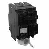
The Record Plus FB line features true one- and two-pole construction, has a double-break contact system for fast response and current limitation to help with arc flash and coordination.

The SACE Tmax XT range offers higher performance, better protection and more precise metering than equivalent units, and can handle from 15 A up to 1200 A.

Combined with precise electronic trip units in small frames, the new range delivers significant time savings and helps to enhance installation quality. Reliability is further increased, and speed of installation improved, thanks to Bluetooth® and Ekip connectivity for mobile devices.

DESCRIPTIVE BULLETIN 15 FB Frame size [A] 100 Pole(s) [No.] 1 2 Rated voltage (AC) 50–60 Hz [V] 600 600 Versions Fixed Fixed Interrupting ratings V N H V N H 240 V (AC) [kA] 35 65 100 65 150 200 277 V (AC) [kA] 35 65 100 - -347 V (AC) [kA] 22 25 35 - -480 V (AC) [kA] - - - 35 65 100 600 V (AC) [kA] - - - 22 25 35 Trip units for power distribution Fixed thermal-magnetic (TMF) • • —
SACE® Tmax® XT range
XT1 XT4 XT5 XT6 XT7 Model Frame size (amps) No. of poles Rated voltage 50–60 Hz AC Interrupt ratings (kA) Dimensions –fixed, 3 poles W x D x H (3) mm (in.) Trip units for power distribution XT1 125 3 480Δ(1) At 240 V AC: N = 50, S = 65, H = 100 At 480 V AC: N = 25, S = 35, H = 65 At 600Y/347 V AC: N = 18, S = 22, H = 25 76.2 x 70 x 130 / (3 x 2.75 x 5.12) TMF XT2 125 3 600 At 240 V AC N = 65, S = 100, H = 150, L = 200, V = 200, X = 200 At 480 V AC N = 25, S = 35, H = 65, L = 100, V = 100, X = 200 At 600 V AC: N = 18, S = 22, H(2) = 25, L(2) = 35, V(2) = 42 90 x 83.56 x 131.1 / (3.54 x 3.29 x 5.16) TMF, Ekip DIP, Ekip Touch XT4 250 3 600 At 240 V AC N = 65, S = 100, H = 150, L = 200, V = 200, X = 200 At 480 V AC N = 25, S = 35, H = 65, L = 100, V = 100, X = 200 At 600 V AC: N = 18, S = 22, H (2) = 25, L (2) = 50, V(2) = 65 105 x 82.5 x 160 / (4.13 x 3.25 x 6.3) TMF, Ekip DIP, Ekip Touch XT5 400–600 3 600 At 240 V AC N = 65, S = 100, H = 150, L = 200, V = 200, X = 200 At 480 V AC N = 25, S = 35, H = 65, L = 100, V = 100, X = 200 At 600 V AC: N = 18, S = 25, H (2) = 35, L (2) = 65 140 x 103 x 205 / (5.51 x 4.05 x 8.07) TMA, Ekip DIP, Ekip Touch XT6 800 3 600 At 240 V AC: N = 65, S =100, H = 200 At 480 V AC: N = 35, S = 50, H = 65 At 600 V AC: N = 20, S = 25, H =35 210 x 103.5 x 268 / (8.27 x 4.07 x 10.55) TMA, Ekip DIP XT7 800–1000–1200 3 600 At 240 V AC: S =65, H = 100, L = 200 At 480 V AC: S = 50, H = 65, L = 100 At 600 V AC: S = 25, H = 50, L = 65 210 x 167 x 268 / (8.27 x 6.57 x 10.55) Ekip DIP, Ekip Touch (1) Current-limiting circuit breaker in 480 V AC and 600 V AC (2) 600 Y/347 V AC (3) Dimensions include line-side connector and mounting bracket XT2 19

Ekip trip units

Ekip trip units represent a new benchmark for circuit breakers, able to satisfy any performance requirement. These complete, flexible protection trip units can be adapted to the level of protection required, independently of the complexity of the system. The range is available for three levels of performance to meet any requirement, from simple to advanced applications.

Thermal-magnetic trip unit

An easy solution for protection against overloads and short circuits. Available in both fixed and adjustable versions depending on the circuit breaker frame size.

Ekip DIP

As the first level of electronic trip units, Ekip DIP trip units are based on microprocessor technologies designed for high reliability and tripping precision.

Ekip Touch/Hi-Touch

The Ekip Touch/Hi-Touch trip units provide a complete series of protections and high accuracy measurements of all electrical parameters. They are intended to integrate seamlessly with most automation and supervision systems. With a common and intuitive user experience between the SACE® Emax 2 and SACE® Tmax® XT circuit breakers, Ekip Touch/Hi-Touch offer class 1 active energy measurement compliance with IEC 61557-12 and embedded Bluetooth® technology, allowing for fast interaction within a safe distance from the equipment.

Several communication protocols allow users to remotely supervise electrical systems and control the circuit breaker.

Thanks to the maximum flexibility guaranteed by these packages, the Ekip Touch/Hi-Touch trip units are completely customizable and field upgradeable. Depending on the specific trip unit version, different packages are available by default, but all of them can be added to the trip unit.

16 RELIAGEAR ® SB SWITCHBOARDS
20

Table

Default functionalities and upgradeability of the trip units:

• • Available by default

↑ Upgradeable

↑ Some functions available. Upgradeable with the full package.

units

17 DESCRIPTIVE BULLETIN Ekip Touch Ekip Touch measuring Ekip G TouchEkip M Touch Ekip Hi-Touch Ekip G Hi-Touch Standard protection • • • • • • Standard measures • • • • • • Measuring package ↑ • • • • • Voltage protections ↑ ↑ ↑ • • • Frequency protections ↑ ↑ ↑ • • • Power protections ↑ ↑ ↑ ↑ ↑ • Adaptive protections ↑ ↑ ↑ • • • Adaptive protections ↑ ↑ ↑ ↑ • • Network analyzer ↑ ↑ • ↑ • • Advanced voltage protections ↑ ↑ ↑ ↑ ↑ • ROCOF protections ↑ ↑ ↑ ↑ ↑ • Power controller ↑ ↑ ↑ ↑ ↑ ↑
1: Default functionalities and upgradeability of trip
21

Time vs. complexity: Your choice

18 RELIAGEAR ® SB SWITCHBOARDS —
Fast shipping options
Program On Demand On Demand Mid Cycle EXcelerate (CTO) Standard SB –normal Standard SB –normal + Lead time before PFA 2 weeks10 weeks PFA (if needed) Not requiredNot required Not required Often required Required Type SKU SKU Configured to order (CTO) Engineered to order (ETO)Engineered to order (ETO) Number of configurations available 7 7 ~3200 Over 1M Over 1M Current max. (amps) 4000 4000 4000 6000 6000 Enclosure options (NEMA) N1/N3R N1/N3R N1/N3R N1/N3R N1/N3R Interrupting rating 100 kAIC100 kAIC 65/100 kAIC Up to 150 kAIC* Up to 150 kAIC* Voltage max. (volts) 480 V AC480 V AC 480 V AC 600 V AC 600 V AC *200 kAIC with fuses Brand: ReliaGear® SB Updated with Emax 2 22

ReliaGear® SB Switchboards Fast shipping options – EXcelerate

Fast lead time and great flexibility with 3000+ preconfigured options available in empower, ABB Reliagear SB – EXcelerate uses a configure-to-order approach that allows the customer to easily combine pre-engineered sub-assemblies to build switchboards up to six sections, thanks to the streamlined configuration option in empower. The switchboards are sent to manufacture at the moment of the order, eliminating the need for engineering, and the drawings are immediately available in empower, making the process easier and turnaround time faster.

EXcelerate highlights

• 2X faster lead times than standard switchboards

• 300 0+ configurations of simple and midcomplexity switchboards available

• Configured-to-order (CTO) sub-assemblies reduce project cycle times

• Simple selection process results in no engineering interaction, immediate manufacturing and faster delivery

• Available in empower quote

Features and benefits

• 120 0 to 4000 A 3P 4W

• 208 V, 480 V

• Indoor and outdoor enclosures (NEMA 1, NEMA 3R)

• Cop per and aluminum bussing up to 100 kA

• Tma x® XT1 to XT7 distribution breakers (TMA and Ekip DIP, Touch for XT7 1200 A only)

• Fixed section width (determined by amperage) and depth (front and rear aligned)

• Opt ional SPD Type 1 and 2, 125 kA and 200 kA individually mounted

• Opt ional RGM meter 2200, 6000, 6010 and 7000

• Single section shipping split

• Cab le in / cable out for main option

DESCRIPTIVE BULLETIN 19 —
23

ReliaGear® SB Switchboards Fast shipping options – On Demand

ABB's On Demand program provides customers the opportunity to easily order and quickly receive ReliaGear SB Switchboards, with product ready to ship in as few as two weeks.*

The On Demand program can potentially reduce project cycle times, helping customers gain a competitive advantage wherever 24/7 reliability is an absolute necessity.

On Demand program highlights

• Pro duct shipment in as few as two weeks

• Seven pre-configured designs with flexible breaker settings

• Cat alog-number driven for easy ordering

• Potentially reduces project cycle times

Features and benefits

• Main bus, 2000 A or 4000 A, copper bus

• Ema x 2 main device with GF and RELT

• 480/277 V AC maximum at 100 kAIC

• ReliaGear plug-in panel type for easy installation of breakers

• Fully rated bus with provision for future extensions

• Front access only with hinged doors

• Front and rear alignment for splicing sections

• Features XT DIP trip units for maximum flexibility

• RGM 2 200 (2000 A) and RGM 6000 (4000 A) digital power meter provided

• Qualified for seismic ratings per publication

9AKK108466A5933 and OSP-0044-10

• Enclosures available in NEMA Type 1 and 3R

* Items must be in stock to meet two-week delivery timeframe. Pl ease check empower Flow for current availability. 10-week mid cycle also available.

20 RELIAGEAR ® SB SWITCHBOARDS
24
DESCRIPTIVE BULLETIN 21 —
cycle Catalog number Current (A) Voltage (V) Bus bracing/ interrupting rating (kA) Enclosure rating Dimensions (W x H x Dinches) Feeder breakers Feeder breakers spaces XT4-250 AXT5-600 A XT71200 AXT4-250 A Full switchboards SWBSTS20E 2000 480Y/277 100 NEMA 1 70x90x35 8 2 – 2 SWBSTS40E 4000 90x90x35 3 2 2 5 SWBSTS20EN3R 2000 NEMA 3R 70x90x40* 8 2 – 2 SWBSTS40EN3R 4000 90x90x40* 3 2 2 5 Add-on feeder sections SWBSTS20EDIST 2000 NEMA 1 40x90x35 8 2 – 2 SWBSTS40EDIST 4000 50x90x35 3 2 2 5 SWBSTS40EDISTN3R 4000 NEMA 3R 50x90x40* 3 2 2 5
Catalog number Current (A) Voltage (V) Bus bracing/ interrupting rating (kA) Enclosure rating Dimensions (W x H x Dinches) Feeder breakers Feeder breakers spaces XT4-250 AXT5-600 A XT71200 AXT4-250 A Full switchboards SWBSTS20E-M 2000 480Y/277 100 NEMA 1 70x90x35 8 2 – 2 SWBSTS40E-M 4000 90x90x35 3 2 2 5 SWBSTS20EN3R-M 2000 NEMA 3R 70x90x40* 8 2 – 2 SWBSTS40EN3R-M 4000 90x90x40* 3 2 2 5 Add-on feeder sections SWBSTS20EDIST-M 2000 NEMA 1 40x90x35 8 2 – 2 SWBSTS40EDIST-M 4000 50x90x35 3 2 2 5 SWBSTS40EDISTN3R-M 4000 NEMA 3R 50x90x40* 3 2 2 5
25
ReliaGear® SB Switchboards – On Demand Catalog numbers 2-week
*+5" overhang 10-week cycle
*+5" overhang
— Notes 22 RELIAGEAR ® SB SWITCHBOARDS 26
27

ABB Inc.

305 Gregson Drive Cary, NC 27511 USA

electrification.us.abb.com

We reserve the right to make technical changes or modify the contents of this document without prior notice. With regard to purchase orders, the agreed particulars shall prevail. ABB Inc. does not accept any re sponsibility whatsoever for potential errors or possible lack of information in this document.

We reserve all rights in this document and in the subject matter and illustrations contained therein. Any reproduction, disclosure to third parties or utilization of its contents – in whole or in parts – is forbidden without prior written consent of ABB Inc.

2024 ABB
1VAL088301-DB Rev D February 2024
Co pyright©
All rights reserved 28

ReliaGear SB Switchboard EV Grid-to-Charger

The ReliaGear® SB EV Grid-to-Charger switchboards from ABB allows customers to meet deadlines, mitigate supply chain risks, and adapt easily to future EV charger growth demands.Withfastleadtimes,thisstandardizedEVGrid-toChargerofferingtakestheguessworkoutofdeployments.

The program offers six pre-configured designs with flexible breakersettings,helpingcustomersgainacompetitiveedge by reducing project cycle times with cost-effective designs. Future-proofdesignsgivecustomerspeaceofmindtoeasily accommodateadditionalchargerexpansion.

29

• Reduced project cycle time

• Flexib le

• Future-proof design

• Eas y to order

30
DESCRIPTIVE BULLETIN ReliaGear ® SB Switchboard EV Grid-to-Charger

The new EV Grid-to-Charger program for ReliaGear ® SB low voltage switchboard from ABB allows customers to meet deadlines, mitigate supply chain risks, and adapt easily to future charger growth demands.

With fast lead times, this standardized EV Grid-to-Charger offering takes the guesswork out of deployments. The program offers six pre-configured designs with flexible breaker settings, helping customers gain a competitive edge by reducing project cycle times with cost-effective designs. Future-proof designs give customers peace of mind to easily accommodate additional charger expansion.

31
004 – 006 EV Gr id-to-Charger overview 007 ReliaGear® SB 1200 A 008 ReliaGear SB 2000 A 009 ReliaGear SB 3000 A 010 ReliaGear SB 4000 A 011 Utility sections 012 ReliaGear SB 2000 A EUSERC 013 ReliaGear SB 4000 A EUSERC 014 EUSERC utility door kits 32
Table of contents

EV Grid-to-Charger

Overview

The EV Grid-to-Charger program for the ReliaGear ® SB switchboard offers customers fast lead times and the option to choose among six pre-configured switchboard designs.

Reduced project cycle time

• Onsite delivery significantly faster. Helps to meet deadlines and mitigate supply chain risks.

Future-proof design

• The f lexible design easily accommodates future charger changes/upgrades by allowing for easy expansion of the feeder section.

• The d esign allows easy adding/changing of feeder breakers to the existing frame and/or adding an additional feeder frame in the future.

Flexible

• Six standardized engineering designs with flexible breaker settings.

• Utility designed for EUSERC applications with door kits.

Easy to order

• Cat alog-number driven for easy ordering.

• Uni versal design.

4 RELIAGEAR® SB SWITCHBOARD EV GRID-TO-CHARGER PROGRAM
33
The flexible design of SACE® Emax2 and Tmax® XT breakers allows for simple field adjustments to meet a wide variety of applications for today and tomorrow.

With an installed base of thousands of units worldwide, the ReliaGear ® SB switchboard sets the standard for functional, flexible and rugged, durable construction.

The EV Grid-to-Charger program from ABB builds on this reputation by providing customers the opportunity to easily order and quickly receive delivery of ReliaGear SB switchboards significantly faster. The EV Grid-to-Charger program can potentially reduce project cycle times, helping customers gain a competitive advantage wherever 24/7 reliability is an absolute necessity.

Why ReliaGear SB?

The universal design of the ReliaGear

SB

switchboard allows substantial flexibility for a wide variety of customer applications. The modular assembly of the plug-in style connections helps reduce maintenance and assembly while allowing for easy future expansion.

The future-proof design allows the customer to plan ahead to easily accommodate future EV charger additions and expand the feeder section by adding another frame to the existing unit.

The flexible design of SACE® Emax2 and Tmax® XT breakers also allows for simple field adjustments to meet a wide variety of applications. Combined with the ReliaGear plug-in style distribution section bus stack, customers can quickly and easily move breaker locations for maximum flexibility.

Features and benefits

• Main bus 1200 A, 2000 A, 3000 A or 4000 A

• Aluminum bus

• 480/277 V AC maximum at 65 kAIC

• NEM A 3R with rodent barriers

• Space heaters with thermostat

• Large hinged covers with DIN rail backplate to allow for easy field upgrades such as communications and remote control

• SACE Emax2 main device with touch trip unit, GF and RELT

• Tma x XT DIP trip units on feeders for maximum ampacity flexibility

• ReliaGear SB plug-in panel type for easy breaker installation and removal

• Fully rated bus with provision for future extensions

• Front access only with hinged doors

• Front and rear alignment for splicing sections

• Qualified for seismic ratings per publication 9AKK108466A5933 and OSP-0044-10

• Surge protection included in each board (SPD Type 2, 200 kA)

DESCRIPTIVE BULLETIN 5
34

EV G2C switchboard

Main characteristics

Configurations available on demand

The EV Grid-to-Charger program offers six preconfigured ReliaGear ® SB designs:

• ReliaGear SB 1200 A

• ReliaGear SB 2000 A

• ReliaGear SB 3000 A

• ReliaGear SB 4000 A

• ReliaGear SB 2000 A EUSERC

• ReliaGear SB 4000 A EUSERC

Pages 7 through 13 show detailed drawings of these six configurations.

• DIN rail backplate to allow fo r easy field upgrades such as communications and remote control

Ordering

ReliaGear EV Grid-to-Charger switchboard catalog numbers have been added to both empower Flow and empower Quote. If adding in empower Quote, it is important to ensure there is adequate stock at the time of quotation and order entry.

• Ant i-rodent barrier

• Pre -installed heaters to protect in cold and/or damp weather

• NEM A 3R outdoor rated enclosure

• Pre -selected feeders to meet popular EV charger sizes

• Ele ctronic breakers with a wide range of settings to accommodate project variations

• Surge protection included in each board

6 RELIAGEAR® SB SWITCHBOARD EV GRID-TO-CHARGER PROGRAM
35
DESCRIPTIVE BULLETIN 7 — ReliaGear ® SB 1200 A Catalog no. RSBG4126A3RBBA Configuration covers the following number of chargers: Qty 4: 150 – 180 kW Level 3 Overhang Front (5 in) Front Plan View Top Conduit Area Bottom Conduit Area 25 Front Plan View 5 25 5 45 Section 01 All ribs shown are 1" wide. Contractor to visually inspect roof brace locations before installing any top conduits. 14.5 8 TYP ReliaGear Series 45 by ABB 5 13 6 6 3 9 33 Conduit Area 15D x W 91" 5" 5 SIDE VIEW 25 .5 OVERHANG 90" 1.5" OVERHANG VENTED LOUVERS 1.5" OVERHANG VENTED LOUVERS Conduit Area 9 33 SEE PLAN VIEW 3.12 (TYP) 2.5 ISSUED: MADE BY: REL BY: JOB NAME: CUSTOMER: CUST. ORDER NO: REQN. NO: ORDER NO: NO DATE REVISIONS INITIALS SHEET ITEM PLANT: MARK: GTCS01 10/02/2023 GTSO12345 Switchboard AndreeC ACP 45 Conduit Detail HiRes 7.0.2011 MAIN ELECTRIC SUPPLY CO LLC, RIVERSIDE Total Line Up Width: RSBG4126A3RBBA MONTERREY GTSO12345 Grid to Charger Standardized Offering 27-CD1 1200A GROUP - DIP SwitchBoard / Device Information Poles Circuit No. Device Amps Lugs/Cable Size Notes Amps TripSensor Nameplates 1XT5H400 3 13,14 (2) - 2/0 - 250 MCM CU - Mech. AL2XT5H400 3 13,14 (2) - 2/0 - 250 MCM CU - Mech. AL3XT5H400 3 13,14 (2) - 2/0 - 250 MCM CU - Mech. AL4XT5H400 3 13,14 (2) - 2/0 - 250 MCM CU - Mech. ALMainXT7H1200 3 9,10,11,12 1200 NOTES: 1. Switchboard furnished with a rainproof TYPE 3R (non-walk-in) enclosure. NOTE: See plan view for details.Need additonal 1 inch space clearance on top and 1.5 inch clearance on the rear of the swbd. 2. Equipment ground bus furnished with lugs. 3. Switchboard qualified for Seismic Ratings per publication DET-463 and OSP-0044-10. 4. Switchboard furnished with Nameplates. 5. All Nameplates to be fastened with screws. 6. Switchboard furnished with hinged gutter covers. 7. Switchboard furnished with fully rated panel. 8. User Specified Layout 9. Device is furnished with integral ground fault protection. 10. Device is furnished with RELT (Reduced Energy Let Through). 11. Device requires RELT or ZSI feature if Authority having jurisdiction has adopted NEC 2014 code requirements. 12. Device Furnished with Ekip Touch (LSIG) Programmer. 13. Device Furnished with Pll Fixed Padlock - Open 14. Device Furnished with Thermal-Magnetic Adjustable Trip. 15. Switchboard furnished with Type 2 SPD HE 200kA per mode / 400kA per phase, 200kAIC. SPD furnished with Indicating Lights, Alarm, Form C Contacts, Surge Counter & Disconnect Switch. QUOTE NO: ITEM NO: MARKS: SHEET: DEV.MIN.INT.RATING (RMS SYM): BUS BRACING (RMS SYM): VOLTAGE: ACCESS TO: STYLE: LABEL: CLASS: RATING: PLATE: BUS MTL: AMPERE: PHASE: ReliaGear Switchboard DRAWING NO: PROJECT NAME DATE: PRODUCT NAME: CUSTOMER: DRAWING TITLE: CREATED BY: REVISION NO.: 27 1200A GROUP - DIP 1 of 3 Fully Rated ReliaGear 65000A 65000A 480/277V U/L SE 1 Front Only Tin Plate 1200A 3P4W UAF-00009500 Grid to Charger Standardized Offering MAIN ELECTRIC SUPPLY CO LLC, RIVERSIDE 2/23/2023 W2 Date:12/13/2023 4:27:34 PM Device Malmud, Lee 8 Information SPD Type2200K 15 45 RG1S Al (3) 500 750 MCM Al Cbl UL SE 1200A 1200A M 40x 90 3 Main 1 1 6 64 14 N G E D 01 Front View Bussing Diagram C-20 1200A Provision for future extensions by ABB ReliaGear Series E H 1200A G N TVSS SEE PLAN VIEW (TYP) (For Specific Counduit Space) 2.5 ISSUED: ACCESS TO: CLASS: LABEL: VOLTAGE: BUS BRACING (RMS SYM) STYLE: MADE BY: REL BY: JOB NAME: CUSTOMER: CUST. ORDER NO: REQN. NO: ORDER NO: NODATE REVISIONS INITIALS SHEET ITEM PHASE: AMPERE: PLATE: RATING: BUS MTL: PLANT: MARK: 1 1200 Al 750A in² Fully 65000 MAIN ELECTRIC SUPPLY CO LLC, RIVERSIDE A 10/02/2023 65000 Switchboard TM HiRes 7.0.2011 Front Only AndreeC ACP DEV. MIN. INT. RATING (RMS SYM) Total Line Up Width: ReliaGear U/L SE 45 A RSBG4126A3RBBA 27-FV1 Tin Plate Grid to Charger Standardized Offering GTCS01 MONTERREY GTSO12345 480Y/277V 3P4W GTSO12345 1200A GROUP DIP NOTES: 1 Swi tchboard furnished with a rainproof type 3R flat roof (non-walk-in) enclosure. Note: See plan view for details. Need additional 1 inch space clearance on top and 1.5 inch clearance on the rear of the switchboard. 2 Equipment ground bus furnished with lugs. 3 Swi tchboard qualified for seismic ratings per publication DET-463 and OSP-0044-10. 4 Swi tchboard furnished with nameplates. 5 All n ameplates to be fastened with screws. 6 Swi tchboard furnished with hinged gutter covers. 7 Swi tchboard furnished with fully rated panel. 8 Use r-specified layout. 9 Dev ice is furnished with integral ground fault protection. 10 Dev ice is furnished with RELT (reduced energy let through). 11 Dev ice requires RELT or ZSI feature if authority having jurisdiction has adopted NEC 2014 code requirements. 12 Dev ice furnished with Ekip Touch (LSIG) Programmer. 13 Dev ice furnished with PLL fixed padlock — open. 14 Dev ice furnished with EKIP DIP (LSI) programmer. 15 Swi tchboard furnished with Type 2 SPD HE 200 kA per mode / 400 kA per phase, 200 kAIC. SPD furnished with indicating lights, alarm, form C contacts, surge counter and disconnect switch. PS Al (3) 500 750 MCM Al Cbl M 1200A 1200A Bussing Diagram C-20 1200A Provision for future extensions ReliaGear Series by ABB 1200A G N SEE PLAN VIEW 3.12 .625 DIA (TYP) (For Specific Counduit Space) 2.5 ISSUED: ACCESS TO: CLASS: LABEL: VOLTAGE: BUS BRACING (RMS SYM) STYLE: MADE BY: REL BY: JOB NAME: CUSTOMER: CUST. ORDER NO: REQN. NO: ORDER NO: NODATE REVISIONS INITIALS SHEET ITEM PHASE: AMPERE: PLATE: RATING: BUS MTL: PLANT: MARK: 1 1200 Al 750A / in² Fully 65000 MAIN ELECTRIC SUPPLY CO LLC, RIVERSIDE A 10/02/2023 65000 Switchboard TM HiRes 7.0.2011 Front Only AndreeC ACP DEV. MIN. INT. RATING (RMS SYM) Total Line Up Width: ReliaGear U/L SE 45 A RSBG4126A3RBBA 27-FV1 Tin Plate Grid to Charger Standardized Offering GTCS01 MONTERREY GTSO12345 480Y/277V 3P4W GTSO12345 1200A GROUP - DIP FRONT VIEW 6 6 90 991 lbs (Est.) 45 8 1 UL E SE U S S A C RG1S H I N G E D 64 1 2 3 4 Main TVSS 40X 1 Space Heater 36

18 Dev ice furnished with EKIP DIP (LSI) programmer.

19 Dev ice furnished with PLL fixed padlock–open.

20 Prov ision for future extension.

21 Dev ice is furnished with RELT-Ekip signaling 2K3 module. 22 Dev ice is furnished with measuring package.

8 RELIAGEAR® SB SWITCHBOARD EV GRID-TO-CHARGER PROGRAM — ReliaGear ® SB 2000 A Catalog no. RSBG4206A3RBBA Configuration covers the following number of chargers: Qty 4: 150 – 350 kW Level 3 Front (5 in) Overhang Front Plan View Front Plan View Top Conduit Area Bottom Conduit Area 35 5 5 30 40 35 40 30 Section 01 Section 02 35 35 All ribs shown are 1" wide. Contractor to visually inspect roof brace locations before installing any top conduits. 11.5 8 TYP ReliaGear Series by ABB 2 5 13 3 7 6 6 6 30 Conduit Area Conduit Area 32 25 D D Conduit Area 25W 5" 5 SIDE VIEW 91" 35 .5 OVERHANG 1.5" OVERHANG VENTED LOUVERS 90" 1.5" OVERHANG VENTED LOUVERS 19D x 28W SEE PLAN VIEW 3.12 .625 DIA (TYP) (For Specific Counduit Space) ISSUED: MADE BY: REL BY: JOB NAME: CUSTOMER: CUST. ORDER NO: REQN. NO: ORDER NO: NO DATE REVISIONS INITIALS SHEET ITEM PLANT: MARK: 2023523G2C 06/26/2023 159999998 Switchboard TM AndreeC ACP 70 Conduit Detail HiRes 7.0.2011 GEXPRO, CHARLOTTE Total Line Up Width: MONTERREY 159999998 RSBG4206A3RBBA Grid to Charger Standardized Offering 20-CD1 2000A NEVI MEASURING Circuit No. Device Amps Poles Lugs Notes NOTES: 18,19 23 Al (2) 500 - 600 MCM Cu Cbl 3 18,19 Al (2) 500 - 600 MCM Cu Cbl 3 3 600 XT5H600 XT5H600 600 1 3 00 Al (2) 500 - 600 MCM Cu Cbl 18,19 SPD Type2200K 8,9,10,11,12,13 14,21,22 4 XT5H600 TVSS 600 600 3 2000 3 Al (2) 500 - 600 MCM Cu Cbl Main 18,19 E2.2SF 2 XT5H600 Switchboard/Device Information Nameplates ReliaGear Series by ABB 13 1 Switchboard furnished with a rainproof TYPE 3R Flatroof (non walk-in) enclosure. 2 Listed NEMA 3R rated Hub and Conduit should be used to maintain environmental integrity of the enclosure. 3 Equipment ground bus furnished with lugs. 4 Switchboard furnished with Nameplates. 5 Switchboard furnished with Seismic Zone 3/4. 6 Shipping splits between each section, ship each section separately. 7 Switchboard furnished with section space heaters. 8 Device is furnished with 250V Bell Alarm. 9 Device furnished with EKIP Touch LSIG trip unit. 10 Device furnished with RELT.Wire per diagram RELT INDIVIDUAL EKIP. 11 Device is furnished with 24V - 48V DC Ekip Supply. 12 Device furnished with (PLC) Open Position - Padlock Device furnished with PLL Fixed Padlock - Open. Device furnished with 24V (4Q) Auxiliary Contacts. 14 Device furnished with 110-120V AC/DC (YO) Opening Coil. 15 Space heater control power circuit wired per sheet 10087742 Sheet 2. 16 Switchboard furnished with hinged gutter covers. 17 Switchboard furnished with fully rated panel. 18 Device furnished with EKIP DIP (LSI) programmer. 19 Device is furnished with Measuring Package. 20 Provision For Future Extension. 21 Device is furnished with RELT-Ekip Signalling 2K3 module. 22 23 Switchboard furnished with Type 2 TVSS/SPD HE 200kA per mode / 400kA per phase, 200kAIC. TVSS SPD furnished with Indicating Lights, Alarm, Form C Contacts, Surge Counter & Disconnect Switch. Insert screens on NEMA 3R enclosure over vent opening 24 25 Use sealing provision bolts on the line side of the main breaker in order to meet EUSERC SEE PLAN VIEW 3.12 .625 DIA (TYP) (For Specific Counduit Space) ISSUED: ACCESS TO: CLASS: LABEL: VOLTAGE: BUS BRACING (RMS SYM) STYLE: MADE BY: REL BY: JOB NAME: CUSTOMER: CUST. ORDER NO: REQN. NO: ORDER NO: NODATE REVISIONS INITIALS SHEET ITEM PHASE: AMPERE: PLATE: RATING: BUS MTL: PLANT: MARK: 2 2000 Al 750A in² Fully 65000 GEXPRO, CHARLOTTE A 02/10/2023 65000 Switchboard TM HiRes 7.0.2011 Front Only AndreeC ACP DEV. MIN. INT. RATING (RMS SYM) Total Line Up Width: ReliaGear U/L SE 70 A RSBG4206A3RBBA 20-DS1 Tin Plate Grid to Charger Standardized Offering 2023523G2C MONTERREY 152GRID2C 480Y/277V 3P4W 152GRID2C 2000A NEVI MEASURING NOTES: 1 Swi tchboard furnished with a rainproof type 3R flat roof (non walk-in) enclosure. 2 Lis ted NEMA 3R rated hub and conduit should be used to maintain environmental integrity of the enclosure. 3 Equipment ground bus furnished with lugs. 4 Swi tchboard furnished with nameplates. 5 Swi tchboard furnished with seismic zone 3/4. 6 Shi pping splits between section; each section ships separately. 7 Swi tchboard furnished with section space heaters. 8 Dev ice is furnished with 250 V bell alarm. 9 Dev ice furnished with EKIP Touch LSIG trip unit.
10 Dev ice furnished with RELT. Wire per diagram RELT individual EKIP.
11 Dev ice is furnished with 24 V–48 V DC Ekip Supply.
12 Dev ice furnished with (PLC) open position padlock.
13 Dev ice furnished with 24 V (4Q) auxiliary contacts.
14 Dev ice furnished with 110–120 V AC/DC (YO) opening coil.
15 Space heater control power circuit wired per sheet 10087742 sheet 2.
16 Swi tchboard furnished with hinged gutter covers.
17 Swi tchboard furnished with fully rated panel.
Swi tchboard furnished
Type 2 TVSS/SPD HE
kA per mode / 400 kA per phase, 200 kAIC. TVSS SPD furnished with Indicating lights, alarm, Form C contacts, surge counter and disconnect switch. 24 Insert screens on NEMA 3R enclosure over vent opening
Use sealing provision bolts on
line side of the main breaker
order to meet EUSERC. RELT Main UL UL SE 90 40 30 2000A 2000A Space Heater Main - Line 40x PER PH & N (8) 750 MCM RG1S Mech (2 Hole) AL RELT HEATER Main E2.2SF TVSS ReliaGear Series by ABB 2000A 14 8 6 64 24 8 20 12 H/C 12 H/C H Front View Bussing Diagram C-35 C-35 2000A 2000A 2000A 2000A G N Provision for future extensions E 01 E E 02 N G D SEE PLAN VIEW 3.12 .625 DIA (TYP) (For Specific Counduit Space) 2.5 ISSUED: ACCESS TO: CLASS: LABEL: VOLTAGE: BUS BRACING (RMS SYM) STYLE: MADE BY: REL BY: JOB NAME: CUSTOMER: CUST. ORDER NO: REQN. NO: ORDER NO: NODATE REVISIONS INITIALS SHEET ITEM PHASE: AMPERE: PLATE: RATING: BUS MTL: PLANT: MARK: 2 2000 Al 750A in² Fully 65000 GEXPRO, CHARLOTTE A 06/26/2023 65000 Switchboard TM HiRes 7.0.2011 Front Only AndreeC ACP DEV. MIN. INT. RATING (RMS SYM) Total Line Up Width: ReliaGear U/L SE 70 A 2023523G2C RSBG4206A3RBBA 20-FV1 Tin Plate Grid to Charger Standardized Offering MONTERREY 159999998 480Y/277V 3P4W 159999998 2000A NEVI MEASURING RELT Main UL UL SE RELT Main PS 90 40 30 2000A 2000A Space Heater Main - Line 40x PER PH & N (8) 750 MCM RG1S Mech (2 Hole) AL RELT HEATER 1 Main E2.2SF 2 TVSS 3 4 1 ReliaGear Series by ABB 2000A 3X FILLER 1X FILLER 3X FILLER 1X FILLER 3X FILLER 1X FILLER 14 8 6 64 24 8 20 12 H/C 12 H/C H Front View Bussing Diagram 1X FILLER C-35 C-35 2000A 2000A 2000A 2000A G N Provision for future extensions E 01 E E 02 N G D SEE PLAN VIEW 3.12 .625 DIA (TYP) (For Specific Counduit Space) 2.5 ISSUED: ACCESS TO: CLASS: LABEL: VOLTAGE: BUS BRACING (RMS SYM) STYLE: MADE BY: REL BY: JOB NAME: CUSTOMER: CUST. ORDER NO: REQN. NO: ORDER NO: NODATE REVISIONS INITIALS SHEET ITEM PHASE: AMPERE: PLATE: RATING: BUS MTL: PLANT: MARK: 2 2000 Al 750A in² Fully 65000 GEXPRO, CHARLOTTE A 06/26/2023 65000 Switchboard TM HiRes 7.0.2011 Front Only AndreeC ACP DEV. MIN. INT. RATING (RMS SYM) Total Line Up Width: ReliaGear U/L SE 70 A 2023523G2C RSBG4206A3RBBA 20-FV1 Tin Plate Grid to Charger Standardized Offering MONTERREY 159999998 480Y/277V 3P4W 159999998 2000A NEVI MEASURING 37
23
with
200
25
the
in
DESCRIPTIVE BULLETIN 9 — ReliaGear ® SB 3000 A Catalog no. RSBG4306A3RBBA Release for manufacturing 11/14/23 KRV (5 in) Overhang R Front Bottom Conduit Area 35 Top Conduit Area Front Plan View 5 35 Front Plan View 5 30 55 Section 01 Section 02 35 35 All ribs shown are 1" wide. 55 installing any top conduits. 11.5 8 TYP ReliaGear Series 30 by ABB 2 13 3 7 9 Conduit Area 25D 40W 91" 5" 5 SIDE VIEW 35 .5 OVERHANG 90" 1.5" OVERHANG VENTED LOUVERS 1.5" OVERHANG VENTED LOUVERS Conduit Area 19D 43W 5 Conduit Area D x 2 7 6 6 Contractor to visually inspect roof brace locations before SEE PLAN VIEW 3.12 .625 DIA (TYP) (For Specific Counduit Space) ISSUED: MADE BY: REL BY: JOB NAME: CUSTOMER: CUST. ORDER NO: REQN. NO: ORDER NO: NO DATE REVISIONS INITIALS SHEET ITEM PLANT: MARK: 2023523G2C 06/28/2023 159999998 Switchboard TM Karina Rdz KRV 85 Conduit Detail HiRes 7.0.2011 GEXPRO, CHARLOTTE Total Line Up Width: 30 MONTERREY 159999998 Grid to Charger Standardized Offering 30-CD1 3000A NEVI MEASURING NOTES: 1 Swi tchboard furnished with a rainproof type 3R flat roof (non walk-in) enclosure. 2 Lis ted NEMA 3R rated hub and conduit should be used to maintain environmental integrity of the enclosure. 3 Equipment ground bus furnished with lugs. 4 Swi tchboard furnished with nameplates. 5 Swi tchboard furnished with seismic zone 3/4. 6 Shi pping splits between sections; each section ships separately. 7 Swi tchboard furnished with section space heaters. 8 Space heater control power circuit wired per sheet RSBCSH480A. 9 Swi tchboard furnished with hinged gutter covers. 10 Swi tchboard furnished with fully rated panel. 11 Dev ice furnished with EKIP DIP (LSI) programmer. 12 Dev ice furnished with PLL fixed padlock - open. 13 Prov ision for future extension. 14 Swi tchboard furnished with Type 2 TVSS/SPD HE 200 kA per mode / 400 kA per phase, 200 kAIC. TVSS SPD furnished with Indicating lights, alarm, form C contacts, surge counter and disconnect switch. 15 Dev ice programmer LT target set at 0.9 for a 3000 A trip. 16 Dev ice is furnished with 250 V bell alarm. 17 Dev ice furnished with EKIP Touch LSIG trip unit. 18 Dev ice furnished with RELT. 19 Dev ice furnished with 24 V (4Q) auxiliary contacts. 20 Dev ice is furnished with 24 V–48 V DC Ekip Supply. 21 Dev ice is furnished with RELT-Ekip Signaling 2K3 module. Wire per 75B661010SH30. 22 Dev ice furnished with 110–120 V AC/DC (YO) opening coil. 23 Dev ice furnished with (PLC) open position — padlock Circuit No. Device Amps Poles Lugs Notes NOTES: 11/14/23 R KRV Release for manufacturing Al (2) 2/0 - 500 MCM Cu Cbl 11,12 4 XT5H600 XT5H600 3 600 11 3 11,12 Al (2) 2/0 - 500 MCM Cu Cbl Al (2) 500 - 600 MCM Cu Cbl 3 600 XT5H600 2 5 Al (2) 500 - 600 MCM Cu Cbl XT5H600 600 600 3 3 XT5H600 14 Al (2) 2/0 - 500 MCM Cu Cbl 1 11 0 6 SPD Type2200K XT5H600 0 600 TVSS 3 15,16,17,18,19,20 21,22,23 3 Al (2) 2/0 - 500 MCM Cu Cbl 11,12 3000 3 Switchboard/Device Information Nameplates ReliaGear Series by ABB 600 Main 1 Switchboard furnished with a rainproof TYPE 3R Flatroof (non walk-in) enclosure. 2 Listed NEMA 3R rated Hub and Conduit should be used to maintain environmental integrity of the enclosure. 3 Equipment ground bus furnished with lugs. 4 Switchboard furnished with Nameplates. 5 Switchboard furnished with Seismic Zone 3/4. 6 Shipping splits between each section, ship each section separately. 7 Switchboard furnished with section space heaters. 8 Space heater control power circuit wired per sheet RSBCSH480A. 9 Switchboard furnished with hinged gutter covers. 10 Switchboard furnished with fully rated panel. 11 Device furnished with EKIP DIP (LSI) programmer. 12 Device furnished with PLL Fixed Padlock - Open. 13 Provision For Future Extension. 14 Switchboard furnished with Type 2 TVSS/SPD HE 200kA per mode / 400kA per phase, 200kAIC. TVSS SPD furnished with Indicating Lights, Alarm, Form C Contacts, Surge Counter & Disconnect Switch. 15 Device programmer LT target set @ 0.9 for a 3000A trip. 16 Device is furnished with 250V Bell Alarm. 17 Device furnished with EKIP Touch LSIG trip unit. 18 Device furnished with RELT. 19 Device furnished with 24V (4Q) Auxiliary Contacts. 20 Device is furnished with 24V - 48V DC Ekip Supply. 21 Device is furnished with RELT-Ekip Signalling 2K3 module. W ire per 75B661010SH30. 22 Device furnished with 110-120V AC/DC (YO) Opening Coil. 23 Device furnished with (PLC) Open Position - Padlock E4.2SF 11 SEE PLAN VIEW .625 DIA (TYP) (For Specific Counduit Space) 2.5 ISSUED: ACCESS TO: CLASS: LABEL: VOLTAGE: BUS BRACING (RMS SYM) STYLE: MADE BY: REL BY: JOB NAME: CUSTOMER: CUST. ORDER NO: REQN. NO: ORDER NO: NODATE REVISIONS INITIALS SHEET ITEM PHASE: AMPERE: PLATE: RATING: BUS MTL: PLANT: MARK: 2 3000 Al 750A in² Fully 65000 GEXPRO, CHARLOTTE A 06/28/2023 65000 Switchboard TM HiRes 7.0.2011 Front Only Karina Rdz KRV DEV. MIN. INT. RATING (RMS SYM) Total Line Up Width: ReliaGear U/L SE 90 A 30 30-DS1 Tin Plate Grid to Charger Standardized Offering 2023523G2C MONTERREY 159999998 480Y/277V 3P4W 159999998 3000A NEVI MEASURING PER PH & N Mech (2 Hole) AL Main Line (10) 750 MCM UL UL SE Main KRV 2000A 3000A 40x Space Heater 11/14/23 90 30 55 Release for manufacturing RELT HTR RGO R 6 5 1X FILLER 3X FILLER 3X FILLER 1X FILLER 8H/C 20 12H/C 14 H N G E D H N G E D TVSS 8H/C Front View Bussing Diagram 64 C-25 C-25 3000A 3000A 3000A 3000A G N Provision for future extensions 1 E4.2SF 3000A Main 24 by ABB ReliaGear Series E E 01 02 N G 12H/C SEE PLAN VIEW (TYP) (For Specific Counduit Space) 2.5 ISSUED: ACCESS TO: CLASS: LABEL: VOLTAGE: BUS BRACING (RMS SYM) STYLE: MADE BY: REL BY: JOB NAME: CUSTOMER: CUST. ORDER NO: REQN. NO: ORDER NO: NODATE REVISIONS INITIALS SHEET ITEM PHASE: AMPERE: PLATE: RATING: BUS MTL: PLANT: MARK: 1 3000 Al 750A in² Fully 65000 GEXPRO, CHARLOTTE A 06/28/2023 65000 Switchboard TM HiRes 7.0.2011 Front Only Karina Rdz KRV DEV. MIN. INT. RATING (RMS SYM) Total Line Up Width: ReliaGear U/L SE 85 A 30 30-FV1 Tin Plate Grid to Charger Standardized Offering 2023523G2C MONTERREY 480Y/277V 3P4W RSBG4306A3RBBA 3000A NEVI MEASURING Configuration covers the following number of chargers: Qty 6: 150 – 350 kW Level 3 PER PH & N Mech (2 Hole) AL Main Line (10) 750 MCM UL UL SE Main KRV 2000A 3000A 40x RELT Main PS Space Heater 11/14/23 90 30 55 Release for manufacturing RELT HTR RGO R 6 5 3 2 1X FILLER 1X FILLER 3X FILLER 3X FILLER 1 1X FILLER 1X FILLER 3X FILLER 8H/C 6 20 12H/C 14 H N G E D H N G E D 3X FILLER 4 TVSS 3X FILLER 1X FILLER 8H/C Front View Bussing Diagram 64 C-25 C-25 3000A 3000A 3000A 3000A G N Provision for future extensions 1 E4.2SF 3000A Main 24 by ABB ReliaGear Series E E 01 02 RELT N G 12H/C SEE PLAN VIEW 3.12 .625 DIA (TYP) (For Specific Counduit Space) 2.5 ISSUED: ACCESS TO: CLASS: LABEL: VOLTAGE: BUS BRACING (RMS SYM) STYLE: MADE BY: REL BY: JOB NAME: CUSTOMER: CUST. ORDER NO: REQN. NO: ORDER NO: NODATE REVISIONS INITIALS SHEET ITEM PHASE: AMPERE: PLATE: RATING: BUS MTL: PLANT: MARK: 1 3000 Al 750A in² Fully 65000 GEXPRO, CHARLOTTE A 06/28/2023 65000 Switchboard TM HiRes 7.0.2011 Front Only Karina Rdz KRV DEV. MIN. INT. RATING (RMS SYM) Total Line Up Width: ReliaGear U/L SE 85 A 30 30-FV1 Tin Plate Grid to Charger Standardized Offering 2023523G2C MONTERREY 480Y/277V 3P4W RSBG4306A3RBBA 3000A NEVI MEASURING 38

Configuration covers the following number of chargers:

10 RELIAGEAR® SB SWITCHBOARD EV GRID-TO-CHARGER PROGRAM — ReliaGear ® SB 4000 A Catalog no. RSBG4406A3RBBA NOTES: 1 Swi tchboard furnished with a rainproof type 3R flat roof (non walk-in) enclosure. 2 Lis ted NEMA 3R rated hub and conduit should be used to maintain environmental integrity of the enclosure. 3 Equipment ground bus furnished with lugs. 4 Swi tchboard furnished with nameplates. 5 Swi tchboard furnished with seismic zone 3/4. 6 Shi pping splits between sections; each section ships separately. 7 Insert screens on NEMA 3R enclosure over vent openings. 8 Use sealing provision bolts on the line side of the main breaker in order to meet EUSERC. 9 Swi tchboard furnished with section space heaters. 10 Dev ice is furnished with 250 V bell alarm. 11 Dev ice furnished with EKIP Touch LSIG trip unit. 12 Dev ice furnished with RELT. Wire per 75B661010SH30. 13 Dev ice is furnished with 24 V–48 V DC Ekip supply. 14 Dev ice furnished with (PLC) open position padlock 15 Dev ice furnished with 24 V (4Q) auxiliary contacts. 16 Dev ice furnished with 110–120 V AC/DC (YO) opening coil. 17 Space heater control power circuit wired per sheet RSBCSH480A. 18 Swi tchboard furnished with hinged gutter covers. 19 Swi tchboard furnished with fully rated panel. 20 Dev ice furnished with EKIP DIP (LSI) programmer. 21 Dev ice furnished with PLL fixed padlock open. 22 Prov ision for future extension. 23 Dev ice is furnished with RELT-Ekip signaling 2K3 module. 24 Swi tchboard furnished with Type 2 TVSS/SPD HE 200 kA per mode / 400 kA per phase, 200 kAIC. TVSS SPD furnished with indicating lights, alarm, Form C contacts, surge counter and disconnect switch. KRV Release for manufacturing PER PH & N RELT HTR (14) 750 MCM Mech (2 Hole) AL Main Line 4000A UL UL UL SE 4000A 2000A Main RELT Main PS Space Heater 40x 40x 40 40 40 2000A RG1S RG1S R 90 11/14/23 2 4 3 5 7 TVSS 8 1 6 4000A 3X FILLER 1X FILLER 6 8H/C 24 6 8H/C 14 64 20 64 14 H H N N G G E E E6.2HF Main 3X FILLER Front View Bussing Diagram C-25 C-25 C-25 4000A 4000A 4000A 4000A 4000A 4000A G N Provision for future extensions by ABB ReliaGear Series E E E 03 02 01 D RELT D 12H/C 12H/C SEE PLAN VIEW 3.12 .625 DIA (TYP) (For Specific Counduit Space) 2.5 ISSUED: ACCESS TO: CLASS: LABEL: VOLTAGE: BUS BRACING (RMS SYM) STYLE: MADE BY: REL BY: JOB NAME: CUSTOMER: CUST. ORDER NO: REQN. NO: ORDER NO: NODATE REVISIONS INITIALS SHEET ITEM PHASE: AMPERE: PLATE: RATING: BUS MTL: PLANT: MARK: 2 4000 Al 750A / in² Fully 65000 GEXPRO, CHARLOTTE A 06/28/2023 65000 Switchboard TM HiRes 7.0.2011 Front Only Karina Rdz KRV DEV. MIN. INT. RATING (RMS SYM) Total Line Up Width: ReliaGear U/L SE 120 A , 40 40-FV1 Tin Plate Grid to Charger Standardized Offering 2023523G2C MONTERREY 480Y/277V 3P4W RSBG4406A3RBBA 4000A NEVI MEASURING Circuit No. Device Amps Poles Lugs Notes Release for manufacturing 11/14/23 NOTES: KRV R 20,21 20,21 600 20 600 3 XT5H600 3 Al (2) 500 - 600 MCM Cu Cbl Al (2) 2/0 - 500 MCM Cu Cbl 3 20 Main E6.2HF 4 XT5H600 XT5H600 3 600 XT5H600 3 600 5 Al (2) 500 - 600 MCM Cu Cbl 20 Al (2) 500 - 600 MCM Cu Cbl 3 600 7 XT5H600 XT5H600 2 600 Al (2) 500 - 600 MCM Cu Cbl 3 600 3 Al (2) 500 - 600 MCM Cu Cbl 20,21 XT5H600 24 8 XT5H600 1 600 20 3 00 Al (2) 500 - 600 MCM Cu Cbl TVSS 20,21 SPD Type2200K 10,11,12,13,14,15 16,23 Al (2) 500 - 600 MCM Cu Cbl Switchboard/Device Information Nameplates ReliaGear Series by ABB 1 Switchboard furnished with a rainproof TYPE 3R Flatroof (non walk-in) enclosure. 2 Listed NEMA 3R rated Hub and Conduit should be used to maintain environmental integrity of the enclosure. 3 Equipment ground bus furnished with lugs. 4 Switchboard furnished with Nameplates. 5 Switchboard furnished with Seismic Zone 3/4. 6 Shipping splits between each section, ship each section separately. 7 Install screens on NEMA 3R enclosure over vent openings 8 Use sealing provision bolts on the line side of the main breaker in order to meet EUSERC 9 Switchboard furnished with section space heaters. 10 Device is furnished with 250V Bell Alarm. 11 Device furnished with EKIP Touch LSIG trip unit. 12 Device furnished with RELT. Wire per 75B661010SH30. 13 Device is furnished with 24V - 48V DC Ekip Supply. 14 Device furnished with (PLC) Open Position - Padlock 15 Device furnished with 24V (4Q) Auxiliary Contacts. 16 Device furnished with 110-120V AC/DC (YO) Opening Coil. 17 Space heater control power circuit wired per sheet RSBCSH480A. 18 Switchboard furnished with hinged gutter covers. 19 Switchboard furnished with fully rated panel. 20 Device furnished with EKIP DIP (LSI) programmer. 21 Device furnished with PLL Fixed Padlock - Open. 22 Provision For Future Extension. 23 Device is furnished with RELT-Ekip Signalling 2K3 module. 24 Switchboard furnished with Type 2 TVSS/SPD HE 200kA per mode / 400kA per phase, 200kAIC. TVSS SPD furnished with Indicating Lights, Alarm, Form C Contacts, Surge Counter & Disconnect Switch. 3 4000 6 SEE PLAN VIEW 3.12 .625 DIA (TYP) (For Specific Counduit Space) 2.5 ISSUED: ACCESS TO: CLASS: LABEL: VOLTAGE: BUS BRACING (RMS SYM) STYLE: MADE BY: REL BY: JOB NAME: CUSTOMER: CUST. ORDER NO: REQN. NO: ORDER NO: NODATE REVISIONS INITIALS SHEET ITEM PHASE: AMPERE: PLATE: RATING: BUS MTL: PLANT: MARK: 2 4000 Al 750A in² Fully 65000 GEXPRO, CHARLOTTE A 06/28/2023 65000 Switchboard TM HiRes 7.0.2011 Front Only Karina Rdz KRV DEV. MIN. INT. RATING (RMS SYM) Total Line Up Width: ReliaGear U/L SE 120 A 40 40-DS1 Tin Plate Grid to Charger Standardized Offering 2023523G2C MONTERREY 159999998 480Y/277V 3P4W 159999998 4000A NEVI MEASURING Release for manufacturing 11/14/23 KRV R (5 in) Overhang Front Front Plan View Top Conduit Area Bottom Conduit Area 35 5 35 Front Plan View 5 40 40 40 40 40 40 Section 01 Section 03 Section 02 35 35 All ribs shown are 1" wide. Contractor to visually inspect roof brace locations before installing any top conduits. 11.5 11.5 8 TYP 8 TYP ReliaGear Series 2 5 2 5 13 13 3 3 7 7 6 6 6 9 6 6 9 6 Conduit Area Conduit Area Conduit Area 25 25 25D x D x 25 25 25W W W 91" 5" 5 SIDE VIEW 35 .5 OVERHANG 90" 1.5" OVERHANG VENTED LOUVERS 1.5" OVERHANG VENTED LOUVERS Conduit Area Conduit Area by ABB SEE PLAN VIEW (TYP) (For Specific Counduit Space) 2.5 ISSUED: MADE BY: REL BY: JOB NAME: CUSTOMER: CUST. ORDER NO: REQN. NO: ORDER NO: NO DATE REVISIONS INITIALS SHEET ITEM PLANT: MARK: 2023523G2C 06/28/2023 159999998 Switchboard Karina Rdz KRV 120 Conduit Detail HiRes 7.0.2011 GEXPRO, CHARLOTTE Total Line Up Width: 40 MONTERREY 159999998 Grid to Charger Standardized Offering 40-CD1 4000A NEVI MEASURING KRV Release for manufacturing PER PH & N HTR (14) 750 MCM Mech (2 Hole) AL Main Line 4000A UL UL UL SE 4000A 2000A Main Space Heater 40x 40x 40 40 40 2000A RG1S RG1S R 90 11/14/23 TVSS 2X FILLER 4000A 1X FILLER 3X FILLER 1X FILLER 2X FILLER 6 8H/C 24 6 8H/C 14 64 20 64 14 H H N N G G E E 3X FILLER E6.2HF Main Front View Bussing Diagram C-25 C-25 C-25 4000A 4000A 4000A 4000A 4000A 4000A G N Provision for future extensions 1 by ABB ReliaGear Series E E E 03 02 01 D D 12H/C 12H/C SEE PLAN VIEW 3.12 .625 DIA (TYP) (For Specific Counduit Space) 2.5 ISSUED: ACCESS TO: CLASS: LABEL: VOLTAGE: BUS BRACING (RMS SYM) STYLE: MADE BY: REL BY: JOB NAME: CUSTOMER: CUST. ORDER NO: REQN. NO: ORDER NO: NODATE REVISIONS INITIALS SHEET ITEM PHASE: AMPERE: PLATE: RATING: BUS MTL: PLANT: MARK: 2 4000 Al 750A in² Fully 65000 GEXPRO, CHARLOTTE A 06/28/2023 65000 Switchboard TM HiRes 7.0.2011 Front Only Karina Rdz KRV DEV. MIN. INT. RATING (RMS SYM) Total Line Up Width: ReliaGear U/L SE 120 A 40 40-FV1 Tin Plate Grid to Charger Standardized Offering 2023523G2C MONTERREY 480Y/277V 3P4W RSBG4406A3RBBA 4000A NEVI MEASURING
8:
39
Qty
150 – 350 kW Level 3

Utility sections

EUSERC Utilities — Hard bussed

For switchboards requiring EUSERC utility sections there are two preconfigured options available.

• ReliaGear ® SB 2000 A — EUSERC

• ReliaGear SB 4000 A — EUSERC

Each option offers the utility section hard bussed, and it is delivered with pre-mounted Group 1 door kit (see page 14). If the required utility is in Groups 2, 3 or 4, then the customer can purchase a dedicated door kit and replace the factoryinstalled Group 1 door kit.

Non-EUSERC Utilities — Cable connected

For non-EUSERC utility, the utility section can be cable connected to the Grid-to-Charger switchboard. When paired with an order for an EV G2C switchboard, a special fast track cycle can be requested when a single utility section is ordered. The process is as follows:

1. Design the utility section desired in empower Quote.

2. Add the Reference Sales Order # of your ReliaGear EV G2C switchboard in the Drawing Notes section of empower.

3. Sel ect Short Cycle or “S” in the drop-down menu in the pricing tab to activate the fast cycle.

If a utility section is ordered together with an EV Grid-toCharger switchboard, skip step 2 and select the Short Cycle as per step 3.

DESCRIPTIVE BULLETIN 11 —
EUSERC switchboard with pre-mounted Group 1 door kit
40
Non-EUSERC switchboard with utility section ordered separately

between sections; each section ships separately. 25 Swi tchboard furnished with Type 2 TVSS/SPD HE 200 kA per mode / 400 kA per phase, 200 kAIC. TVSS

12 RELIAGEAR® SB SWITCHBOARD EV GRID-TO-CHARGER PROGRAM — ReliaGear ® SB 2000 A — EUSERC Catalog no. RSBG4206A3RBBE 01/17/24 R Release for manufacturing Overhang Front (4 in) KRV Front Plan View Top Conduit Area Bottom Conduit Area 40 Front Plan View 11 40 11 40 30 40 30 Section 03 Section 01 Section 02 40 40 All ribs shown are 1" wide. Contractor to visually inspect roof brace locations before installing any top conduits. 11.5 8 TYP ReliaGear Series 40 40 by ABB 2 13 3 7 3 6 3 3 Conduit Area Conduit Area 30 34D 34 25 W 4"11 SIDE VIEW 91" 40 .5 OVERHANG 1.5" OVERHANG VENTED LOUVERS 90" 1.5" OVERHANG VENTED LOUVERS Conduit Area 24D 28W SEE (For Specific ISSUED: MADE BY: REL BY: JOB NAME: CUSTOMER: CUST. ORDER NO: REQN. NO: ORDER NO: NO DATE REVISIONS INITIALS SHEET PLANT: MARK: 07/12/2023 RSBG4206A3RBBE Switchboard TM Karina Rdz KRV 110 Conduit Detail HiRes 7.0.2011 GEXPRO, CHARLOTTE Total Line Up Width: MONTERREY RSBG4206A3RBBE Grid to Charger Standardized Offering 50-CD1 2000A EUSERC NOTES: 1 Swi tchboard furnished with a rainproof type 3R flat roof (non-walk-in) enclosure. 2 Lis ted NEMA 3R rated hub and conduit should be used to maintain environmental integrity of the enclosure. 3 Equipment ground bus furnished with lugs. 4 Swi tchboard furnished with nameplates. 5 Swi tchboard furnished with seismic zone 3/4. 6 Insert screens on NEMA 3R enclosure over vent openings. 7 Use sealing provision bolts on the line side of the main breaker in order to meet EUSERC. 8 Swi tchboard furnished with section space heaters. 9 Dev ice is furnished with 250 V bell alarm. 10 Dev ice furnished with EKIP Touch LSIG trip unit. 11 Dev ice furnished with RELT. 12 Dev ice is furnished with 24 V–48 V DC Ekip Supply. 13 Dev ice furnished with (PLC) open position — padlock 14 Dev ice furnished with 24 V (4Q) auxiliary contacts. 15 Dev ice furnished with 110–120 V AC/DC (YO) opening coil. 16 Swi tchboard furnished with hinged gutter covers. 17 Swi tchboard furnished with fully rated panel. 18 Dev ice furnished with EKIP DIP (LSI) programmer. 19 Dev ice furnished with PLL fixed padlock — open. 20 Dev ice is furnished with RELT-Ekip signaling 2K3 module. 21 EUSERC utility section(s) furnished with handles and sealing provisions per EUSERC specifications. 22 Ins tallation note: Caution: If switchboard is installed on a housekeeping slab greater than 2 1 2 ", the meter may be over the 6 3" maximum allowable meter height. Consult utility if you need more information. 23 Space heater control power circuit wired per sheet 10087742 Sheet 2. 24 Shi pping splits
SPD
2000A RELT HTR 2000A UL UL UL SE Main specifications per power company Lug provisions only U Space Heater Flanged 40x MS MS 30 7 RG1S 40 30 40 90 8H/C 16 12 24 64 8H/C 6 2 Sockets 15 Clips 16 14 1X FILLER 3X FILLER I 2X FILLER E 20 3 3X FILLER 24 1X FILLER H 3X FILLER G N D Front View Bussing Diagram T-25 T-30 C-30 C-30 2000A 2000A 2000A 2000A 2000A 2000A 2000A G N TVSS 3 2 1 4 2000A U Main E2.2SF by ABB ReliaGear Series E S E 01 02 03 RELT N BASE PLATE 18" FOR COMPONENTS MOUNTING SEE PLAN VIEW 3.12 .625 DIA (TYP) (For Specific Counduit Space) 2.5 ISSUED: ACCESS TO: CLASS: LABEL: VOLTAGE: BUS BRACING (RMS SYM) STYLE: MADE BY: REL BY: JOB NAME: CUSTOMER: CUST. ORDER NO: REQN. NO: ORDER NO: NODATE REVISIONS INITIALS SHEET ITEM PHASE: AMPERE: PLATE: RATING: BUS MTL: PLANT: MARK: 2 2000 Al 750A / in² Fully 65000 GEXPRO, CHARLOTTE A 07/12/2023 65000 Switchboard TM HiRes 7.0.2011 Front Only Karina Rdz KRV DEV. MIN. INT. RATING (RMS SYM) Total Line Up Width: ReliaGear U/L SE 110 A NA 1 Tin Plate Grid to Charger Standardized Offering MONTERREY RSBG4206A3RBBE 480Y/277V 3P4W RSBG4206A3RBBE 2000A EUSERC CODE: PT COMPT UTILITY PER EUSERC PG. METER PER EUSERC PG. UGPS PER PG. LUG LANDING PER PACIFIC GAS & ELECTRIC PG 326, 333 345 347 322, 330 SAN FRANCISCO, CA Circuit No. Device Amps Poles Lugs Notes NOTES: 18,19 Al (2) 500 - 600 MCM Cu Cbl Al (2) 500 - 600 MCM Cu Cbl 0 18,19 0 3 3 600 XT5H600 1 600 XT5H600 3 3 Al (2) 500 - 600 MCM Cu Cbl 25 SPD Type2200K 9,10,11,12,13,14 15,20 4 E2.2SF XT5H600 TVSS 600 600 3 3 Al (2) 500 - 600 MCM Cu Cbl Main 2000 2 XT5H600 Switchboard/Device Information Nameplates ReliaGear Series by ABB Device furnished with (PLC) Open Position - Padlock 1 Switchboard furnished with a rainproof TYPE 3R Flatroof (non walk-in) enclosure. 2 Listed NEMA 3R rated Hub and Conduit should be used to maintain environmental integrity of the enclosure. 3 Equipment ground bus furnished with lugs. 4 Switchboard furnished with Nameplates. 5 Switchboard furnished with Seismic Zone 3/4. 6 Insect screens on NEMA 3R enclosure over vent openings 7 Use sealing provision bolts on the line side of the main breaker in order to meet EUSERC 8 Switchboard furnished with section space heaters. 9 Device is furnished with 250V Bell Alarm. 10 Device furnished with EKIP Touch LSIG trip unit. 11 Device furnished with RELT. 12 Device is furnished with 24V - 48V DC Ekip Supply. 13 20 14 Device furnished with 24V (4Q) Auxiliary Contacts. 15 Device furnished with 110-120V AC/DC (YO) Opening Coil. 16 Switchboard furnished with hinged gutter covers. 17 Switchboard furnished with fully rated panel. 18 Device furnished with EKIP DIP (LSI) programmer. 19 Device furnished with PLL Fixed Padlock - Open. Space heater control power circuit wired per sheet 10087742 Sheet 2. Device is furnished with RELT-Ekip Signalling 2K3 module. 21 EUSERC utility section(s) furnished with handles and sealing provisions per EUSERC specifications. 22 INSTALLATION NOTE: Caution: If switchboard is installed on a housekeeping slab greater than 2-1/2" the meter may be over the 6'3" maximum allowable meter height. Consult Utility if you need more information. 23 24 Shipping splits between each section, ship each section separately. 25 Switchboard furnished with Type 2 TVSS/SPD HE 200kA per mode / 400kA per phase, 200kAIC. TVSS SPD furnished with Indicating Lights, Alarm, Form C Contacts, Surge Counter & Disconnect Switch. 18,19 18,19 SEE PLAN VIEW 3.12 (TYP) (For Specific Counduit Space) 2.5 ISSUED: ACCESS TO: CLASS: LABEL: VOLTAGE: BUS BRACING (RMS SYM) STYLE: MADE BY: REL BY: JOB NAME: CUSTOMER: CUST. ORDER NO: REQN. NO: ORDER NO: NODATE REVISIONS INITIALS SHEET ITEM PHASE: AMPERE: PLATE: RATING: BUS MTL: PLANT: MARK: 2 2000 Al 750A in² Fully 65000 GEXPRO, CHARLOTTE A 10/02/2023 65000 Switchboard TM HiRes 7.0.2011 Front Only AndreeC ACP DEV. MIN. INT. RATING (RMS SYM) Total Line Up Width: ReliaGear U/L SE 105 A RSBG4206A3RBBE 50-DS1 Tin Plate Grid to Charger Standardized Offering 2023523G2C MONTERREY 152GRID2C 480Y/277V 3P4W 152GRID2C 2000A EUSERC RG1S 2000A 2000A Main UL UL UL SE RELT Main PS specifications Space Heater Lug provisions only per power company U 30 MS Flanged 40x MS 7 SPD RELT HTR 40 35 30 90 RELT BASE PLATE 16" FOR COMPONENTS MOUNTING IN SECTION 02 14 2 Sockets 15 Clips 16 8 24 24 20 3 12 N G E 8 6 16 64 E S 2 H 1 Front View Bussing Diagram D 4 T-20 T-30 C-30 C-30 2000A 2000A 800A 2000A 2000A 2000A 800A G N Main U 2000A E2.2SF 1 ReliaGear Series by ABB 02 E 03 01 SEE PLAN VIEW 3.12 .625 DIA (TYP) (For Specific Counduit Space) 2.5 ISSUED: ACCESS TO: CLASS: LABEL: VOLTAGE: BUS BRACING (RMS SYM) STYLE: MADE BY: REL BY: JOB NAME: CUSTOMER: CUST. ORDER NO: REQN. NO: ORDER NO: NODATE REVISIONS INITIALS SHEET ITEM PHASE: AMPERE: PLATE: RATING: BUS MTL: PLANT: MARK: 2 2000 Al 750A in² Fully 65000 GEXPRO, CHARLOTTE A 10/02/2023 65000 Switchboard TM HiRes 7.0.2011 Front Only AndreeC ACP DEV. MIN. INT. RATING (RMS SYM) Total Line Up Width: ReliaGear U/L SE 105 A 2023523G2C RSBG4206A3RBBE 50-FV1 Tin Plate Grid to Charger Standardized Offering MONTERREY 152GRID2C 480Y/277V 3P4W 152GRID2C 2000A EUSERC CODE: PT COMPT UTILITY PER EUSERC PG. METER PER EUSERC PG. UGPS PER PG. LUG LANDING PER PACIFIC GAS & ELECTRIC PG 326, 333 345 347 320 SAN FRANCISCO, CA Configuration covers the following number of chargers: Qty 4: 150 – 350 kW Level 3 41
furnished with indicating lights, alarm, Form C contacts, surge counter and disconnect switch.
DESCRIPTIVE BULLETIN 13 — ReliaGear ® SB 4000 A — EUSERC Catalog no. RSBG4406A3RBBE Release for manufacturing Overhang Front (4 in) Front Plan View Front Plan View Top Conduit Area Bottom Conduit Area 50 11 50 11 50 40 40 40 50 40 40 50 40 50 Section 01 Section 05 Section 03 Section 02 Section 04 50 50 All ribs shown are 1" wide. Contractor to visually inspect roof brace locations before installing any top conduits. 11.5 11.5 8 TYP 8 TYP 8.5 8 TYP ReliaGear Series by ABB 2 2 5 13 13 20.000 3 20.000 3 7 7 6 6 6 6 6 6 6 3 3 9 Conduit Area Conduit Area 40 40D x D 25 25W W 4"11 SIDE VIEW 91" 50 .5 OVERHANG 1.5" OVERHANG VENTED LOUVERS 90" 1.5" OVERHANG VENTED LOUVERS Conduit Area Conduit Area Conduit Area 17 17 D x D x 28 28 W W SEE PLAN VIEW .625 DIA (For Specific Counduit Space) 2.5 ISSUED: MADE BY: REL BY: JOB NAME: CUSTOMER: CUST. ORDER NO: REQN. NO: ORDER NO: NO DATE REVISIONS INITIALS SHEET ITEM PLANT: MARK: 06/28/2023 RSBG4406A3RBBE Switchboard Karina Rdz KRV 220 Conduit Detail HiRes 7.0.2011 GEXPRO, CHARLOTTE Total Line Up Width: 60 MONTERREY RSBG4406A3RBBE Grid to Charger Standardized Offering 60-CD1 4000A EUSERC Release for manufacturing 01/17/24 KRV Overhang Front (4 in) R Front Plan View Front Plan View Top Conduit Area Bottom Conduit Area 50 11 50 11 50 40 40 40 50 40 40 50 40 50 Section 01 Section 05 Section 03 Section 02 Section 04 50 50 All ribs shown are 1" wide. Contractor to visually inspect roof brace locations before installing any top conduits. 11.5 11.5 8 TYP 8 TYP 8.5 8 TYP ReliaGear Series by ABB 2 2 13 13 20.000 20.000 7 7 6 6 6 6 6 6 3 3 Conduit Area Conduit Area Conduit Area 44 40 40D x D x D x 25 25 44 W W W 4"11 SIDE VIEW 91" 50 .5 OVERHANG 1.5" OVERHANG VENTED LOUVERS 90" 1.5" OVERHANG VENTED LOUVERS Conduit Area Conduit Area 17 17 D x D x 28 28 W W SEE PLAN VIEW .625 DIA (TYP) (For Specific Counduit Space) 2.5 ISSUED: MADE BY: REL BY: JOB NAME: CUSTOMER: CUST. ORDER NO: REQN. NO: ORDER NO: NO DATE REVISIONS INITIALS SHEET ITEM PLANT: MARK: 06/28/2023 RSBG4406A3RBBE Switchboard Karina Rdz KRV 220 Conduit Detail HiRes 7.0.2011 GEXPRO, CHARLOTTE Total Line Up Width: 60 MONTERREY RSBG4406A3RBBE Grid to Charger Standardized Offering 60-CD1 4000A EUSERC NOTES: 1 Swi tchboard furnished with a rainproof type 3R flat roof (non-walk-in) enclosure. 2 Lis ted NEMA 3R rated hub and conduit should be used to maintain environmental integrity of the enclosure. 3 Equipment ground bus furnished with lugs. 4 Swi tchboard furnished with nameplates. 5 Swi tchboard furnished with seismic zone 3/4. 6 Insert screens on NEMA 3R enclosure over vent openings 7 Use sealing provision bolts on the line side of the main breaker in order to meet EUSERC 8 Swi tchboard furnished with section space heaters. 9 Dev ice is furnished with 250 V bell alarm. 10 Dev ice furnished with EKIP Touch LSIG trip unit. 11 Device furnished with RELT. 12 Device is furnished with 24 V–48 V DC Ekip Supply. 13 Device furnished with (PLC) open position — padlock 14 Device furnished with 24 V (4Q) auxiliary contacts. 15 Dev ice furnished with 110–120 V AC/DC (YO) opening coil. 16 Space heater control power circuit wired per sheet 10087742 Sheet 2. 17 Swi tchboard furnished with hinged gutter covers. 18 Switchboard furnished with fully rated panel. 19 Device furnished with EKIP DIP (LSI) programmer. 20 Device furnished with PLL fixed padlock — open. 21 Dev ice is furnished with RELT-Ekip signaling 2K3 module. 22 EUSERC utility section(s) furnished with handles and sealing provisions per EUSERC specifications. 23 EUSERC utility section(s) furnished with handles and sealing provisions per EUSERC specifications. 24 Swi tchboard furnished with Type 2 TVSS/SPD HE 200 kA per mode / 400 kA per phase, 200 kAIC. TVSSSPD furnished with Indicating lights, alarm, Form C contacts, surge counter and disconnect switch. 25 Shi pping splits between each section, ship each section separately. 26 INS TALLATION NOTE: Caution: If switchboard is installed on a housekeeping slab greater than 2-1/2 " the meter may be over the 6’3” maximum allowable meter height. Consult Utility if you need more information. 2000A 2000A 2000A 2000A Main RELT Main PS UL UL UL UL UL SE Space Heater U Lug Provisions Only Per Specifications Flanged MS MS 30 40x 40x 7 21 21 21 21 90 RG1S RG1S 40 40 50 40 50 3X FILLER 2X FILLER 3X FILLER 1X FILLER 2 Sockets 15 Clips 14 14 6 6 18 12 7 64 14 16 24 H N N G G E E D D 1X FILLER 8H/C 8H/C 64 24 S Front View Bussing Diagram H T-35 T-30 T-35 T-35 T-35 C-35 C-35 4000A 4000A 4000A 4000A 4000A 4000A 4000A 4000A 4000A 4000A 4000A 4000A 4000A G N TVSS 4000A Main U E6.2HF 1 by ABB ReliaGear Series S E E E 03 05 02 04 01 BASE PLATE 18" FOR COMPONENTS MOUNTING RELT SEE PLAN VIEW 3.12 .625 DIA (TYP) (For Specific Counduit Space) 2.5 ISSUED: ACCESS TO: CLASS: LABEL: VOLTAGE: BUS BRACING (RMS SYM) STYLE: MADE BY: REL BY: JOB NAME: CUSTOMER: CUST. ORDER NO: REQN. NO: ORDER NO: NODATE REVISIONS INITIALS SHEET ITEM PHASE: AMPERE: PLATE: RATING: BUS MTL: PLANT: MARK: 2 4000 Al 750A in² Fully 65000 GEXPRO, CHARLOTTE A 06/28/2023 65000 Switchboard TM HiRes 7.0.2011 Front Only Karina Rdz KRV DEV. MIN. INT. RATING (RMS SYM) Total Line Up Width: ReliaGear U/L SE 220 A 1 Tin Plate Grid to Charger Standardized Offering NA MONTERREY RSBG4406A3RBBE 480Y/277V 3P4W RSBG4406A3RBBE 4000A EUSERC PT COMPT UTILITY PER EUSERC PG. METER PER EUSERC PG. UGPS PER PG. LUG LANDING PER CODE: PACIFIC GAS & ELECTRIC PG 326, 333 345 347 324, 330 SAN FRANCISCO, CA Circuit No. Device Amps Poles Lugs Notes NOTES: XT5H600 9,10,11,12,13,14 15,21 XT5H600 4 19,20 5 3 Al (2) 500 - 600 MCM Cu Cbl 600 19,20 3 Al (2) 500 - 600 MCM Cu Cbl Al (2) 500 - 600 MCM Cu Cbl 600 19,20 Main E6.2HF 4000 3 XT5H600 XT5H600 3 600 19,20 3 2 XT5H600 Al (2) 500 - 600 MCM Cu Cbl 600 19,20 3 19,20 600 7 3 XT5H600 600 Al (2) 500 - 600 MCM Cu Cbl 3 Al (2) 500 - 600 MCM Cu Cbl 24 Al (2) 500 - 600 MCM Cu Cbl 1 19,20 XT5H600 8 XT5H600 0 600 0 3 SPD Type2200K TVSS Al (2) 500 - 600 MCM Cu Cbl 19,20 600 3 Switchboard/Device Information Nameplates ReliaGear Series by ABB 6 Device is furnished with 24V - 48V DC Ekip Supply. 1 Switchboard furnished with a rainproof TYPE 3R Flatroof (non walk-in) enclosure. 2 Listed NEMA 3R rated Hub and Conduit should be used to maintain environmental integrity of the enclosure. 3 Equipment ground bus furnished with lugs. 4 Switchboard furnished with Nameplates. 5 Switchboard furnished with Seismic Zone 3/4. 6 Install screens on NEMA 3R enclosure over vent openings 7 Use sealing provision bolts on the line side of the main breaker in order to meet EUSERC 8 Switchboard furnished with section space heaters. 9 Device is furnished with 250V Bell Alarm. 10 Device furnished with EKIP Touch LSIG trip unit. 11 Device furnished with RELT. 12 19 13 Device furnished with (PLC) Open Position - Padlock 14 Device furnished with 24V (4Q) Auxiliary Contacts. 15 Device furnished with 110-120V AC/DC (YO) Opening Coil. 16 Space heater control power circuit wired per sheet 10087742 Sheet 2. 17 Switchboard furnished with hinged gutter covers. 18 Switchboard furnished with fully rated panel. EUSERC utility section(s) furnished with handles and sealing provisions per EUSERC specifications. Device furnished with EKIP DIP (LSI) programmer. 20 Device furnished with PLL Fixed Padlock - Open. 21 Device is furnished with RELT-Ekip Signalling 2K3 module. 23 24 Switchboard furnished with Type 2 TVSS/SPD HE 200kA per mode / 400kA per phase, 200kAIC. TVSS SPD furnished with Indicating Lights, Alarm, Form C Contacts, Surge Counter & Disconnect Switch. 25 Shipping splits between each section, ship each section separately. INSTALLATION NOTE: Caution: If switchboard is installed on a housekeeping slab greater than 2-1/2" the meter may be over the 6'3" maximum allowable meter height. Consult Utility if you need more information. 26 SEE PLAN VIEW .625 DIA (TYP) (For Specific Counduit Space) 2.5 ISSUED: ACCESS TO: CLASS: LABEL: VOLTAGE: BUS BRACING (RMS SYM) STYLE: MADE BY: REL BY: JOB NAME: CUSTOMER: CUST. ORDER NO: REQN. NO: ORDER NO: NODATE REVISIONS INITIALS SHEET ITEM PHASE: AMPERE: PLATE: RATING: BUS MTL: PLANT: MARK: 2 4000 Al 750A in² Fully 65000 GEXPRO, CHARLOTTE A 06/28/2023 65000 Switchboard TM HiRes 7.0.2011 Front Only AndreeC ACP DEV. MIN. INT. RATING (RMS SYM) Total Line Up Width: ReliaGear U/L SE 220 A 2023523G2C 60 60-DS1 Tin Plate Grid to Charger Standardized Offering MONTERREY 152GRID2C 480Y/277V 3P4W 152GRID2C 4000A EUSERC Configuration covers the following number of chargers: Qty 8: 150 – 350 kW Level 3 2000A Main RELT Main PS Space Heater U Flanged MS UL UL UL UL UL SE 7 Per Specifications Lug Provisions Only 21 21 21 21 40x 40x 2000A 90 40 40 MS 50 50 40 2000A 2000A 30 RG1S RG1S HEATER RELT TVSS 1X FILLER 3X FILLER 3X FILLER 14 24 14 14 6 8 18 8 6 24 3X FILLER H H N N G G E E D D 2 Sockets 15 Clips 64 64 16 Front View Bussing Diagram 7 12 4000A T-35 T-35 T-35 T-30 T-35 C-35 C-35 4000A 4000A 4000A 4000A 4000A 4000A 4000A 4000A 4000A 4000A 4000A 4000A 4000A G N Main U E6.2HF 1 by ABB ReliaGear Series E S S 04 E E 05 01 03 02 SEE PLAN VIEW (TYP) (For Specific Counduit Space) 2.5 ISSUED: ACCESS TO: CLASS: LABEL: VOLTAGE: BUS BRACING (RMS SYM) STYLE: MADE BY: REL BY: JOB NAME: CUSTOMER: CUST. ORDER NO: REQN. NO: ORDER NO: NODATE REVISIONS INITIALS SHEET ITEM PHASE: AMPERE: PLATE: RATING: BUS MTL: PLANT: MARK: 2 4000 Al 750A in² Fully 65000 GEXPRO, CHARLOTTE A 06/28/2023 65000 Switchboard TM HiRes 7.0.2011 Front Only AndreeC ACP DEV. MIN. INT. RATING (RMS SYM) Total Line Up Width: ReliaGear U/L SE 220 A 2023523G2C 60 60-FV1 Tin Plate Grid to Charger Standardized Offering MONTERREY 152GRID2C 480Y/277V 3P4W 152GRID2C 4000A EUSERC CODE: PT COMPT UTILITY PER EUSERC PG. METER PER EUSERC PG. UGPS PER PG. LUG LANDING PER PACIFIC GAS & ELECTRIC PG 326, 333 345 347 324, 330 SAN FRANCISCO, CA 1.5 OVERHANG VENTED LOUVRES 1.5 OVERHANG VENTED LOUVRES OVERHANG 42

• EUSERC catalog numbers RSBG4206A3RBBE (2 000 A) and RSBG4406A3RBBE (4000 A) ship with door kit Group 1 as the standard.

• See t able below for alternate door kits for other specific utilities to be ordered separately.

• Simple and fast field installation by removing the pin from the hinge and replacing with the door kit that matches the specific utility required.

14 RELIAGEAR® SB SWITCHBOARD EV GRID-TO-CHARGER PROGRAM —
Group Part number for 2000 A Part number for 4000 A Door kit description 1* 1SQA013209R0001 1SQA014377R0001 15 clip sockets — one 30 " cover with 2 sockets 2** 1SQA013210R0001 1SQA014378R0001 13 clip sockets — one 15" blank cover, one 15" cover with 13 clips, screws 3 1SQA013211R0001 1SQA014379R0001 15 clip sockets — one 15" blank cover, one 15" cover with 15 clips, screws 4 1SQA013212R0001 1SQA014380R0001 Remote sockets — two 15" blank covers, screws
EUSERC utilities and associated door kits NumberEUSERC utility list^ Door kit group Min. height lugs Sockets Number of clips EUSERC page Meter page Door kit part number — 2000 A Door kit part number — 4000 A 1 Southern California Edison Group 1* 42 2 15 322 332 1SQA013209R00011SQA014377R0001 2 Pacific Gas & Electric Co 42 2 15 322 332 1SQA013209R0001 1SQA014377R0001 3 Arizona Public Service Group 2** 42 1 13 322 332 1SQA013210R00011SQA014378R0001 4 Portland General Electric 42 1 13 322 332 1SQA013210R00011SQA014378R0001 5 Seattle City Light 42 1 13 322 332 1SQA013210R00011SQA014378R0001 6 NV Energy 42 1 13 322 332 1SQA013210R00011SQA014378R0001 7 Hawaiian Electric Company Inc 42 1 13 322 332 1SQA013210R00011SQA014378R0001 8 Burkbank Water & Power 42 1 13 322 332 1SQA013210R00011SQA014378R0001 9 Snohomish Country Pud 42 1 13 322 332 1SQA013210R00011SQA014378R0001 10 Public Service Co of NM 42 1 13 322 332 1SQA013210R00011SQA014378R0001 11 Puget Sound Energy 42 1 13 322 332 1SQA013210R00011SQA014378R0001 12 Los Angeles Department Of Water And Power Group 3 42 1 15 322 332 1SQA013211R00011SQA014379R0001 13 San Diego Gas & Electric 42 1 15 322 332 1SQA013211R00011SQA014379R0001 14 Pacificorp Group 4 42 Remote 13 322 332 1SQA013212R00011SQA014380R0001 15 Pacific Power & Light 42 Rem ote 13 322 332 1SQA013212R00011SQA014380R0001 16 Rocky Mountain Power 42 Remote 13 322 332 1SQA013212R00011SQA014380R0001
EV Grid-to-Charger EUSERC utility door kits
Sampling of
* Group 1 door kits ship with switchboard
** If second socket is required, order 2 quantities
^ El ectrical service assumes 3-phase, 4-wire wye configuration
43
44

ABB Inc.

305 Gregson Drive

Cary, NC 27511 USA

abb.com/contacts

abb.com/lowvoltage

We reserve the right to make technical changes or modify the contents of this document without prior notice. With regard to purchase orders, the agreed particulars shall prevail. ABB Inc. does not accept any re sponsibility whatsoever for potential errors or possible lack of information in this document.

We reserve all rights in this document and in the subject matter and illustrations contained therein. Any reproduction, disclosure to third parties or utilization of its contents – in whole or in parts – is forbidden without prior written consent of ABB Inc.

2024 ABB

1SQC088001B02011.2024
pyright©
All rights reserved 45
Co
46
GENERATOR CONNECTION

GenTower Generator Connection

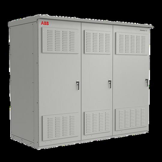
GenTower is a stand-alone, permanent solution. It easily connects a mobile generator to feed the main power system without modifications to the building or the electrical system. This saves costs forbothlaboranddowntime.

Rated up to 4000 amps, it connects either by cabling to the lugs on the main switchboard (if tap connections are in place), with hard bus connection to approved GE switchboards,orthroughafeederbreaker.It'salsoavailable asasectioninanewSpectraSeriesline-up.Thestand-alone version's NEMA 3R enclosure installs in any location accessibletoamobilegenerator.

Thisisalogical,cost-efficientsolutionforanyonewhoneeds to quickly and easily connect a portable generator during a power outage - especially retail, commercial, health care, educationalandmanufacturingfacilities.

47

Restore power quickly and efficiently with GenTower® How to be prepared for anything!

imagination at work

GE Energy
48

GenTower® Generator Connection

Switchboards and Panelboards

Power outages are unpredictable. And they can bring your facility to a halt –for an unknown length of time.

Be ready. With the new GenTower generator connector from GE, you’ll be ready to get the power –and your operation – back up and running quickly.
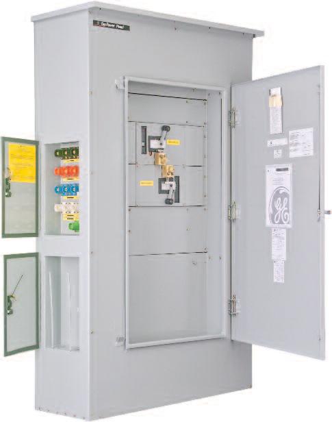
GenTower is a stand-alone, permanent solution. It easily connects a mobile generator to feed the main power system without modifications to the building or the electrical system. This saves costs for both labor and downtime.

The stand-alone version’s NEMA 3R enclosure installs in any location accessible to a mobile generator.

This is a logical, cost-efficient solution for anyone who needs to quickly and easily connect a portable generator during a power outage – especially retail, commercial, health care, educational and manufacturing facilities.

Caps omitted to show connector details 49

Switchboards

Key Features

•Connection via color-coded, cam-lock quick connects and traditional lugs

•Supports help maintain proper connection of cables to quick connects

•Hinged trap door maintains NEMA 3R protection when cables are connected

•Sequence of operation clearly displayed on front cover

•Provisions for mounting key interlocks (Kirk lock and key ordering and coordination with existing/separate equipment is customer’s responsibility)

•UL Listed (UL 891, Switchboards)

• Advanced configurations integrated into switchboard lineups are available with factory support or via Speedi

Selection

*Requires double section configuration

Panelboards

Key Features

• Side entry offers quick and easy generator connection and allows for bottom load exit if required

• Spectra RMS breakers deliver greater flexibility and quicker, more accurate reaction to faults than thermal magnetic breakers

• Two Kirk Key interlocks offer more security than mechanical interlocks, since keys are needed to transfer power

• Top and bottom lugs expand load exit options and reduce cable/wire bending

• Storage compartment allows all compatible connectors can be purchased and stored for quick access

Selection Voltage Amperage Rear Connected Front Connected Catalog Number Dimensions (inches) Approx. Weight (lbs.) Catalog Number Dimensions (inches) Approx. Weight (lbs.) W D H W D H 208/120 800 GQC208800R3R 30 60 90 1300 GQC208800F3R 30 45 90 1200 1000 GQC208100R3R 30 60 90 1300 GQC208100F3R 30 45 90 1200 1200 GQC208120R3R 30 60 90 1300 GQC208120F3R 30 45 90 1200 1600 GQC208160R3R 30 60 90 1300 GQC208160F3R 30 45 90 1200 2000 GQC208200R3R 30 60 90 1525 GQC208200F3R 30 45 90 1424 2500 GQC208250R3R 40 60 90 1775 GQC208250F3R* 75 40 90 3656 3000 - - - - - GQC208300F3R* 75 40 90 3701 4000 - - - - - GQC208400F3R* 80 50 90 3945 480/277 800 GQC480800R3R 30 60 90 1300 GQC480800F3R 30 45 90 1200 1000 GQC480100R3R 30 60 90 1300 GQC480100F3R 30 45 90 1200 1200 GQC480120R3R 30 60 90 1300 GQC480120F3R 30 45 90 1200 1600 GQC480160R3R 30 60 90 1300 GQC480160F3R 30 45 90 1200 2000 GQC480200R3R 30 60 90 1525 GQC480200F3R 30 45 90 1424 2500 GQC480250R3R 40 60 90 1775 GQC480250F3R* 75 40 90 3656 3000 - - - - - GQC480300F3R* 75 40 90 3701 4000 - - - - - GQC480400F3R* 80 50 90 3945 Voltage Amperage Feed Generator Connection Catalog Number Dimensions (inches) Approx. Weight (lbs.) W D H 208Y/120 400A Bottom Left Side GQCP208400BLR 44 20 75 690 Right Side GQCP208400BRR 44 20 75 690 Top Left Side GQCP208400TLR 44 20 75 690 Right Side GQCP208400TRR 44 20 75 690 800A Bottom Left Side GQCP208800BLR 44 20 75 690 Right Side GQCP208800BRR 44 20 75 690 Top Left Side GQCP208800TLR 44 20 75 690 Right Side GQCP208800TRR 44 20 75 690 1200A Bottom Left Side GQCP208120BLR 44 20 75 690 Right Side GQCP208120BRR 44 20 75 690 Top Left Side GQCP208120TLR 44 20 75 690 Right Side GQCP208120TRR 44 20 75 690 480Y/277 400A Bottom Left Side GQCP480400BLR 44 20 75 690 Right Side GQCP480400BRR 44 20 75 690 Top Left Side GQCP480400TLR 44 20 75 690 Right Side GQCP480400TRR 44 20 75 690 800A Bottom Left Side GQCP480800BLR 44 20 75 690 Right Side GQCP480800BRR 44 20 75 690 Top Left Side GQCP480800TLR 44 20 75 690 Right Side GQCP480800TRR 44 20 75 690 50

How to get help recovering!

GenTower helps you prepare for situations that knock your utility power out.

GE helps you recover from emergencies that damage your electrical equipment.

Our emergency response team is prepared to work around the clock to serve you. The program includes the following elements:

• In addition to your local sales representatives, our Customer Service team has the capability to answer calls 24x7 and will add a “natural disaster” prompt, within hours of an emergency situation, that will direct affected callers to this dedicated team.

• We review inventory levels on key component items to ensure sufficient stock for expedited deliveries.

• The factories are prepared to ramp up production on stock items that are typically ordered in your area as well as freeing up short cycle capacity for non-stock equipment items.
If you need information following a disaster, call 1-800-GE-1-Stop 24/7, email emergencyresponseteam@ge.com, or visit www.geindustrial.com/emergencyresponse

Want to get ready? Ask GE about GenTower.

GenTower is a registered trademark of the General Electric Company.

Information provided is subject to change without notice. Please verify all details with GE. All values are design or typical values when measured underlaboratory conditions, and GE makes no warranty or guarantee, express or implied, that such performance will be obtained under end-use conditions.

GE Energy 41 Woodford Avenue, Plainville, CT 06062 www.geindustrial.com

© 2011 General Electric Company

DEA-504B (10/11)
imagination at work
51

INDIVIDUALLY MOUNTED

52

Power Break II Switchboard

ABB's industrial-duty switchboard product line Power Break® II ---features individually-mounted breaker compartments for ABB's complete product family of insulatedcasebreakers.

Power Break II (PB) switchboards can house insulated case circuit breakers as mains, ties, and feeders; and low voltage powercircuitbreakersasmainsandties.

Both switchboard product lines feature protective devices that can be provided with communications capability for connection to ABB's Power Management Control System. Thisswitchboardlinealsofeaturessimpledesignsthatallow for rapid field modification and maintenance - a must for use in applications where system downtime is absolutely unacceptable.

53

DESCRIPTIVE BULLETIN

Power Break II and AV3 switchboard

54
55
3 TABLE OF CONTENTS
04 – 05 Power Break II and AV3 switchboard 06 – 07 PB II insulated case circuit breakers 08 – 09 EntelliGuard G air circuit breakers 10 – 13 Standards and interrupting ratings 56
Table of contents

Power Break II and AV3 switchboard

ABB's industrial-duty switchboard product lines Power Break II and AV-3 Access feature individually-mounted breaker compartments for ABB’s product family of breakers

Power Break II (PB) switchboards can house insulated case circuit breakers as mains, ties, and feeders; and low voltage power circuit breakers as mains and ties. AV-3 Access (AV3) provides individual compartments for molded case breakers serving as mains, ties, or feeders.

Both switchboards lines offer an outstanding cost effective, alternative to the more robust switchgear constructions.

ABB switchboards feature:

• Rugged construction - specially designed bus structure enabling them to withstand the damaging effects of a short circuit for at least 30 cycles - a feature normally found only in switchgear

• Fast cycle times – ABB has a competitive switchboard manufacturing cycle times in the industry

• Broad functionality - similar overall functionality to comparable ANSI-rated switchgear

• Cost effective design - ABB switchboards save you money as functional alternative to switchgear

Both switchboard product lines feature protective devices that can be provided with communications capability for connection to ABB Ability. Both switchboard lines also feature simple designs that allow for rapid field modification and maintenance - a must for use in applications where system downtime is absolutely unacceptable.

Product scope

• Up to 6000A main bus

• 150kAIC @ 480V, 100kAIC @ 600V

• EntelliGuard G mains and ties only up to 6000A

• Power Break II (ICCB) breakers up to 4000A

• Designed, built, and tested in accordance with NEMA PB-2, and listed under UL-891

• AV3 utilizes individual mounted Spectra (MCCB) breakers

Optional features

• Rear extensions to 60, 64 and 74 inch deep frame

• Infrared scanning window in rear doors

• Lockable T-handles on circuit breaker cubicle door

• Lockable T-handles on rear doors

• Overhead breaker lifting hoist

• Section barriers and shutters

Benefits

• Individual breaker compartments, including 100% rated molded case breakers

• Rear cable compartment

• Trip unit display through the breaker escutcheon with metering and trip information

• Industry-exclusive 30-cycle short circuit withstand bus rating up to 85kA

• Standard tin-plated copper main bus

• Standard full-height 2000 amp silver-plated copper vertical bus in AV3

• Compact, modular design allowing 5-high breaker stacks in most cases

• Optional epoxy-coated, insulated/isolated bus with rear and side barriers

• EntelliGuard TU trip unit

• ABB design approach also facilitates field reconfiguration

• Flexibility, reliability, simplicity and safety

• Coordinated to ABB sub-assemblies

• Cycle time to support your needs

4 POWER BREAK II AND AV3 SWITCHBOARD
57

1. Meets UL 891 and NEMA PB-2 standards for switchboard construction

2. Industry-exclusive 30 cycle short circuit withstand bus rating eliminates need for instantaneous tripping

3. Standard tin-plated copper bus

4. Drawout or stationary breakers

5. Indoor and outdoor (walk-in and non-walk-in) enclosure available

6. Individual breakers isolated (top, bottom and rear) from adjacent breaker compartments and main bus/rear cable compartment

7. Drawout breaker can be tilted providing easy inspection and maintenance of primary contact finger assembly

8. Fully equipped solid state MicroVersaTrip Plus™ or PM™ trip

9. New, compact, 100%-rated Power Break II insulated case circuit breaker combines ease of use and state-of-the-art performance in 800A, 1600A, 2000A, 2500A, 3000A, and 4000A frame sizes

10. Smaller Power Break II breaker design, allowing up to 5 breakers to be mounted in the same switchboard stack (some restrictions apply)

11. Convenient access to breaker controls and trip unit

12. Standard hinged doors with quarter-turn latches

DESCRIPTIVE BULLETIN 5
01 01 PBII switchboard with 4 PB2 insulated case 8 12 9 10 11 1 2 3 4 6 7 5
58

PB II insulated case circuit breakers

1. Compact, lightweight design

2. 36-point pre-wired, dedicated secondary terminal block standard (see item 16)

3. Optional mechanical counter

4. Padlock device standard

5. Easy-to-reach ON/OFF buttons

6. EntelliGuard© TU trip units - field upgradable, UL Listed, CSA certified, IEC 947-2 certified

7. Sealable door provides added security

8. Drop-in shunt trip, undervoltage release and bell alarm (with and without manual lockout) modules

9. Flush-mounted pump handle

Power Break II insulated case circuit breakers are highly compact, heavy-duty breakers that combine ease of use, asethetics and state-of-art performances in 200 through 4000-Amp frame sizes, rated for up to 200,000 Amps RMS symmetrical for 240Vac, in drawout and stationary versions.

Available with EntelliGuard TU trip unit with the built-in flexibility required to match your system's needs, whether for optimum safety, optimum system reliability, or both at the same time. Whether you're using all circuit breakers or a mixed system of breakers and fusible devices, the EntelliGuard TU will accommodate your needs with minimal compromise and maximum functionality.

6 POWER BREAK II AND AV3 SWITCHBOARD
2 3 1 4 5 7 6 9 8
02 02 Insulated case circuit breakers 59

Features and benefits

Power Break II insulated case circuit breakers

• Modular, drop-in accessories common to all frame sizes

• Flush-mounted pump handle

• Manually and electrically operated versions in same compact envelope

• Double insulated ON/OFF buttons

• 72-point pre-wired, dedicated secondary terminals

• Modular, field-installable motor operator

• EntelliGuard TU trip unit featuring reduced energy let-through (RELT) setting

• Modular auxiliary switches with up to 12 NO/NC set of contacts

• Charge-after-close mechanism

• Manual discharge of springs without closing

• Suitable for reverse feed

DESCRIPTIVE BULLETIN 7
60

EntelliGuard G air circuit breakers

8 POWER BREAK II AND AV3 SWITCHBOARD
1 2 3 4 5 6 7 8 9 10 12 13 11 1. 78 secondary disconnectscombination terminals 2. Detailed, factory-assembled side label 3. EntelliGuard TU trip unit 4. Rating plug 5. Optional factory-installed interlocks (mechanical or kirk key) 6. Complete, factory-assembled catalog number 03 7. Accessory windows 8. Padlock provision 9. Retractable handle for manual spring charging 10. Command close coil 11. Operating buttons: ON/OFF 12. Breaker status contacts: OPEN/CLOSED Closing spring status: CHARGED/DISCHARGED 13. Tamper-proof breaker label 03 EntelliGuard G air circuit breakers 61

ABB low-voltage air circuit breakers designs rated from 400A to 6000A, with fault interruption ratings up to 200kAIC. Integral to the EntelliGuard G breakers with state-of-the-art EntelliGuard TU trip units, which provide superior system protection, system reliability, monitoring and communications. The breaker-trip unit system delivers superior circuit protection without compromising either selectivity or arc flash protection.

Features and benefits

EntelliGuard G air circuit breaker

• ANSI/UL1066, UL489, carries a UL, cUL and CE label

• Multiple short time bands under 100ms optimally fit above the Instantaneous clearing times

• Alternate instantaneous setting (RELT) mitigates arc flash hazard

• Adjustable ST and GF zone selective Interlocking optimizes restrained and unrestrained bands

• Zone selective instantaneous protection, multiple zone protection, 3 cycle clearing and selectivity are provided simultaneously

• Instantaneous trip adjusts up to 30X trip plug rating

• In addition to arc flash protection and selectivity features, the EntelliGuard TU

• Motor operators

• Closing devices

• Shunt trip for ground fault

• Uvr with fixed time delay

• Second shunt trip or UV release

• Auxiliary switches and contacts

• Bell alarm / trip annunciation

• Breaker mounted key interlock

• Mechanical interlocks – fixed breakers

• Mechanical interlocks – drawout breakers

• Network interlock

• Mechanical operation counter

• Pushbutton padlock device

• Ready-to-close switch

• Secondary disconnect block

• Spring charged contact

EntelliGuard TU

• Instantaneous - zone selective interlocking (I-ZSI) builds on the short time and ground fault interlocking by now providing the ability to overlap the Instantaneous setting on the main and feeder breakers. Now I-ZSI can be used for selectivity

• Instantaneous - waveform recognition instantaneous trip is based on the amount of energy and duration versus a threshold current setting (MVT). Improves coordination with current limiting devices by discerning whether a downstream breaker/fuse is clearing the fault. Provides ability to set the Instantaneous pickup below the peak let thru of a downstream current limiting device while maintaining selectivity

• RELT- reduced energy let through with positive feedback two independent instantaneous settings selectable via an external switch or modbus communications with positive indication via an output contact. Commonly referred to in the industry as an "arc flash switch" or "maintenance switch"

• Additional features and benefits:

- Large backlit LCD screen with detailed descriptions***

- LED health status indicator***

- Status and event log with date/time stamp (10 events)***

- Free set-up software

- Full metering and relaying***

- Thermal memory

- Universal rating plugs

- Programmable input and output relays***

- Meets and surpasses all applicable UL, ANSI, NEMA and IEC standards

- WaveForm capture (4 cycles prior, 4 cycles after, 40 samples/cycle)

- Open communication protocols: Modbus

485 RTU and Profibus (EntelliGuard G breaker Only)***

- Plug and play replacement without breaker rewiring for RMS-9, MVT, MVT+, EPIC, MVT M/PM trip units legacy

***Some options require additional 24 VDC.

DESCRIPTIVE BULLETIN 9
62

Standards and interrupting ratings

10 POWER BREAK II AND AV3 SWITCHBOARD
Equipment Power Break II/AV3 UL 891 Switchboard NEMA PB-2 Insulated case circuit breaker Power Break II/AV3 UL 489 CSA C22.2 No. 5.1 NEMA AB-1 Molded case circuit breaker Spectra UL 489 NEMA AB-1 Low voltage circuit breaker EntelliGuard G ANSI/UL1066 UL489
Interrupting rating tier ANSI/UL1066 devices, LVPCB Envelope 1 Envelope 2 Envelope 3 Code 254V 580V 635V 1/2S Withstand HSIOC Override No.1 Override WI Code 4001200 4002000 3200 4003200 3200 40005000 S 65.000 65.000 50.000 50.000 50.000 49.000 53.500 S • N 65.000 65.000 65.000 65.000 None None None N • • H 85.000 85.000 65.000 65.000 65.000 63.700 69.500 H • P 2 100.000 100.000 65.000 65.000 65.000 63.700 69.500 P • E 85.000 85.000 85.000 85.000 None None None E • M 100.000 100.000 100.000 85.000 85.000 83.800 90.950 M • • B 100.000 100.000 100.000 100.000 None None None B • • L 150.000 150.000 100.000 100.000 100.000 98.000 107.000 L • • Power Break II Frame size 800A 1600A 2000A 2500A 3000A 4000A Standard 240Vac 65 85 85 100 100 100 480Vac 65 65 65 100 100 100 600Vac 50 50 50 85 85 85 250Vac 42 42 42 High-break 240Vac 100 125 125 200 200 200 480Vac 100 100 100 150 150 150 600Vac 65 65 65 100 100 100 Special high-break 750Vac 35 35 35 Short-time (0.5 sec) 25 30 30 42 42 42 Low voltage circuit breakers – main device Insulated case circuit breakers - main and feeder devices 63
Standards Short circuit withstand ratings
DESCRIPTIVE BULLETIN 11
sizing
Power Break II switchboard
Frame size 150A 250A 600A 1200A 240Vac 480Vac 600Vac SEDA SEHA SELA SEPA SFHA SFLA SFPA SGDA SGHA SGLA SGPA SKHA SKLA SKPA 18 65 100 200 65 100 200 65 65 100 200 65 100 200 14 25 65 100 25 65 100 - 35 65 100 50 65 100 10 18 25 25 18 25 25 - 25 65 65 25 42 65
Spectra
Estimate weights and dimensions: Shipping dimensions: 54 inches Weight: 4420 pounds 22 30 1 1 A B C E D C B A F Available compartment height is 84 inches.
Molded case circuit breakers – feed devices for AV3
Break
Left side main section A Aux compartment 42 inches B Main breaker section 2000A 21 inches C Aux compartment 21 inches Right side feeder section A Aux compartment 14 inches B F 800A or 1600A breaker compartment 14 inches 64
Typical layout of Power
II switchboard

1. Selections adjacent to a 4000 A device or EntelliGuard breaker must be a minimum of 30” wide. Add 2” for non walk-in outdoor construction.

2. Feeder devices can be located in the same section with mains rated 3000 A and lower.

3. Horizontal main bus available up to 6000 A.

12 POWER BREAK II AND AV3 SWITCHBOARD
Device Main and tie devices Feeder devices² Manual and electrical operations Manual and electrical operations Type Rating Structure Unit height Section Unit height Section Width Depth Width Depth Insulated case circuit breakers Power Break II 800 Stationary 14" 22" Std 30" Opt 50", 60" 14" 22" 30" 45" Drawout 1600 Stationary Drawout 2000 Stationary Drawout 21" 21" 2500 Stationary 35" 22" 50", 60" 35" 22" 30" 45" Drawout 3000 Stationary 30" Drawout 4000¹ Stationary 42" 22" Std 30" Opt 60" Drawout Low voltage power circuit breaker EntelliGuard G¹ 800 Drawout 21" 22" Std 30" Opt 60" 1600 Drawout 2000 Drawout 3200 Drawout 30" Std 38" Opt 4000 Drawout 5000 Drawout³ 35" 38" 67" 6000 Drawout 65

1. Feeder devices can be located in the same section with mains rated 3000A and lower.

2. Requires 7” blank at top to meet 6’7” rule.

Applications:

• Critical power facilities

• Medium to large commercial and industrial applications

Segments/Industries:

• Data center

• Food and beverage

• Industrial processes

• Waste water

• High/Medium commercial

DESCRIPTIVE BULLETIN 13
Device Main and tie devices Feeder devices¹ Manual and electrical Operations Manual and electrical operations Type Rating Structure Unit height Section Unit height Section Width Depth Width Depth Molded case circuit breaker Spectra 150 80% 14"² 15" 45" 50" 60" 14" 15" 45" 50" 60" 100% 250 80% 100% 600 80% 100% 21" 21" 1200 80% 21", 28" 100% 35" 35" 66
14 POWER BREAK II AND AV3 SWITCHBOARD 67
68

— ABB Inc.

305 Gregson Drive Cary, NC 27511

abb.com/lowvoltage

GE is a trademark of GE. Manufactured by ABB Ltd under license from General Electric Company.

The information contained in this document is for general information purposes only. While ABB strives to keep the information up to date and correct, it makes no representations or warranties of any kind, express or implied, about the completeness, accuracy, reliability, suitability or availability with respect to the information, products, services, or related graphics contained in the document for any purpose. Any reliance placed on such information is therefore strictly at your own risk. ABB reserves the right to discontinue any product or service at any time.

DET-118 Rev B January 2020
Copyright 2020 ABB. All rights
69
©
reserved.

METERING

70

Commercial Metering

ABB's Commercial Metering Switchboard line offers a full line of metering products for the commercial construction market. Ourmodularconstructiontakesuplessspace,isavailablein anfractionofthetimeversusstandardswitchboards,iscost competitive, and can be delivered and installed without specialequipment.

71

Commercial Metering Switchboards

GE Industrial Solutions
72

Section Types

• UL Listed, EUSERC, Non-EUSERC Lever Bypass

• 208Y/120V, 240Y/120V or 480Y/277V

• 100 kAIC, 150 kAIC up to 4000A, 200 kAIC at 3000A and 4000A

• 400, 600, 800, 1000, 1200, 2000, 3000, 4000A

Underground Pull Section

• 100 kAIC

• Bottom feed

• Cu or Al bus

• NEMA 1 or 3R

• NEMA 1 or 3R enclosure

• Bottom feed, center feed, and top busway

• Cu or Al bus

• Refer to Speedi for all sizing

Top Incoming Busway

• 400A-4000A

• NEMA 1 or 3R

Half Height Pull Sections with Single Main Breaker

• 400A-2000A

• G, K and PBII circuit breakers

• HPC and BPS fused switches

• Device padlocking

• SE Barriers

• Equipment ground fault protection on 1200A-2000A (optional on 400A-1000A)

• Front access

Large Tenant Metering

• Hot Sequence Metering

• SG, SK, PBII, BPS, HPC

• Bottom or top exit

• Device padlocking

• Equipment ground fault protection

• Mounting provisions for CTs

• Isolating barriers

• Hinged sealable cover

• Transformer rated meter socket (EUSERC only)

• Front access

• Middle or bottom mounted neutral

• Lever bypass meter sockets available (Non-EUSERC only)

• Submains

• Rear load wire way spacing 8” minimum

Small Tenant Metering

• Cold and hot sequences (hot is default)

• Tenant disconnects SF, T-fuse pullout J fuse constructions:

- SF (100A, 200A)

- T-fuse pull out (100A, 200A)

• 3Ph 4W Service

• 3 pole, 2 pole disconnects

• 600A-4000A horizontal bus

• 25” minimum depth for top or bottom exit - to 60”

• Provisions for field installable socket and breaker additions

• Front access

• 100% rated neutral; standard ground rating

• Middle (EUSERC only) or bottom (Non-EUSERC only) mounted neutral

Distribution Panel

• Interior 2000A, Cu bus, 100 kAIC

• 13, 18x distribution space

• Bolt-on and plug-in

• 3Ph 4W

• Spectra main breaker or main lug only interior

• CT compartment up to 2000A

• Front neutral access

• Submains

• Ringless style sockets, cover contains ring

• Lever bypass meter sockets available (Non-EUSERC only)

• Service entrance barriers (Non-EUSERC only)

• 100 kAIC

• Top and bottom feed exit

• Test bypass block meter socket available

• 5, 7, 13 locking jaw sockets

• Flash shields

• Line lugs at top, customer load connection at bottom

• All disconnects lockable in OFF position

• Rear load wire way spacing 3” minimum

• 3-pack (20” wide) available for both EUSERC and Non-EUSERC

• 6-pack (35” wide) available for EUSERC only

73

Side Load Wireway

• 15” minimum width, copper or aluminum bus

Corner Section

• Copper or aluminum bus

• Available in Speedi

• In most cases a 15” section will be added on each side of the corner

UL Approved Field-Installable Small Tenant Kits

Prewired section meets UL

If Meter Socket exists (chose ST-200A or ST-100A in Speedi) choose the following:

If Meter Socket does not exist (chose ST-200A Space or ST-100A Space in Speedi) choose the following:

Options
Disconnect Rating Cat. No. 35 kAIC SF Breaker 277/480V, 200A 277/480V, 100A CM203MSB600V CM103MSB600V 65 kAIC SF Breaker 277/480V, 200A 277/480V, 100A 120/208V, 200A 120/208V, 100A CM203MSB600VH CM103MSB600VH CM203MSB240V CM103MSB240V T-Fuse Pullout 277/480V, 200A 120/208V, 200A CM203MSTF600V CM203MSTF240V FD1 Switch 277/480V, 200A 277/480V, 100A CM200MSJF600V CM200MSJF240V Disconnect Rating Cat. No. 35 kAIC SF Breaker 277/480V, 200A 277/480V, 100A CM200A35K480V CM100A35K480V 65 kAIC SF Breaker 277/480V, 200A 277/480V, 100A 120/208V, 200A 120/208V, 100A 120/240V, 200A 120/240V, 100A CM200A65K480V CM100A65K480V CM200A65K208V CM100A65K208V CM200A65K240V CM100A65K240V T-Fuse Pullout 277/480V, 200A 120/208V, 200A 120/240V, 200A CM200ATF480V CM200ATF208V CM200ATF240V
Mounting holes use four [18] ¼-20 screws Meter socket assembly [1] Meter socket mounting plate Cover support bracket Meter Spaces 74

Commercial Metering

Now Available On Service Solutions

GE RESOLve ensures your satisfaction by giving you fast and reliable responses to warranty issues, field service requests, missing parts problems or product returns. GE’s national network of factory authorized service operations is ready to meet all your installation, start-up, testing and maintenance needs. 1-888-GE-RESOLve

Web Solutions

www.geindustrial.com is where you’ll find complete, easy-to-use information on the power of the GE Energy package: products, services, support, and solutions.

GE Industrial Solutions 41 Woodford Avenue Plainville, CT 06062 www.geindustrial.com © 2013 General Electric Company DEA-552A 11/13 SPEEDI WIN™ is a trademark of General Electric Company Information provided is subject to change without notice. Please verify all details with GE. All values are design or typical values when measured under laboratory conditions, and GE makes no warranty or guarantee, express or implied, that such performance will be obtained under end-use conditions. 75

PANELBOARDS

76
— Contact your ABB representative for more information or assistance
District | December 2021 Quick Selector Guide 77
Dallas

Table of content

Contacts

Pro-stock unassembled panelboards R-Series panelboards

ReliaGear neXT power panelboards

Retrofit kits for Spectra panelboards

Molded case circuit breakers

Circuit breaker enclosures

Disconnect and safety switches

Dry type transformers

Lighting contactors

SPDs/TVSS

Load centers and circuit breakers

78

Electrical distribution contacts

ABB Distributor customer service

Stock, price and availability

Order status

Expedite requests

Order changes

Order cancellation

E-mail: us-el.distributorsales@abb.com

Phone: 1-800-431-7867, prompt 1

ABB new order entry

Use empower or E-mail us-elgmusorders@abb.com

ABB component support

Technical support product/application inquiries

E-mail: epis.component.support@abb.com

Phone: 1-800-431-7867, prompt 4

ABB post sales and warranty

Defective product warranty issues and inquiries

Use empower or phone 1-800-431-7867, prompt 5

ABB empower help desk

empower technical issues

E-mail: empoweru@abb.com

ABB training

empower training: https://empoweru.lessonly.com/signin

Product training: https://mylearning.abb.com

Buylog and Control Catalog

Please refer to the Buylog and/or Control Catalog for further product information and details. Reach out to your local ABB account manager with any questions

Buylog: https://electrification.us.abb.com/buylog

Control Catalog: https://electrification.us.abb.com/control-catalog

79

Breaker quoting guide

Adding breaker to circuit breaker enclosure

1. Select CB enclosure from CB enclosure tab

2. Select breaker from CCB tab

3. Select lugs from MCCB tab

Adding breaker to Spectra bolt-on panel

1. Select mounting hardware from Retrofit kit for Spectra panelboards tab

2. Select breaker from MCCB tab

3. Select lugs from MCCB tab

Adding main breaker or subfeed breaker to a ReliaGear prostock panel

. Select breaker from Pro-stock tab

Adding breaker to ReliaGear neXT panelboard or ReliaGear switchboard group mounted section

. Select breaker from ReliaGear neXT tab

80

Pro-Stock Panelboards

81

ReliaGear lighting panelboards

Pro-Stock, unassembled lighting panels

100-600A (600A main circuit breaker not available)

240 Vac 1 or 3 phase or 480y/277 vac 3 phase

Order by product number from the customer service center

1. Select interior

Select the interior by bus type, panel rating and number of circuits.

Identify the box/front height for use in Steps 2 and 3.

1 For TGL20 ground lug quantities, see TGL20 Ground Lug Quantities table above.

2 For isolated ground, use EGS12. When using the EGS12, 3, 5 and 7 ground lugs (TGL20s) are required for 18, 30 and 42 circuits respectively.

Voltage Rating (Amps) No. of circuits Feed-thru Non feed-thru Product Number Box/Front Height Product Number Box/Front Height TGL2 Ground Bars1,2 240 Vac, 1 Phase 100-250 18 AQU1182RCXAXT1B4 37.5" AQU1182RCXAXB4 31.5" 2 30 AQU1302RCXAXT1B4 43.5" AQU1302RCXAXB4 37.5" 3 42 AQU1422RCXAXT1B4 49.5" AQU1422RCXAXB4 43.5" 4 400 18 AQU1184RCXAXT1B4 64.5" – – 2 42 AQU1424RCXAXT1B4 76.5" AQU1424RCXAXB4 64.5" 4 600 18 AQU1186RCXAXT1B4 64.5" – – 2 42 AQU1426RCXAXT1B4 76.5" AQU1426RCXAXB4 64.5" 4 208/120 Vac, 3 Phase 100-250 18 AQU3182RCXAXT1B4 37.5" AQU3182RCXAXB4 31.5" 2 30 AQU3302RCXAXT1B443.5" AQU3302RCXAXB4 37.5" 3 42 AQU3422RCXAXT1B4 49.5" AQU3422RCXAXB4 43.5" 4 400 18 AQU3184RCXAXT1B464.5" – – 2 42 AQU3424RCXAXT1B4 76.5" AQU3424RCXAXB4 64.5" 4 600 18 AQU3186RCXAXT1B464.5" – – 2 42 AQU3426RCXAXT1B4 76.5" AQU3426RCXAXB4 64.5" 4 480/277 Vac, 3 Phase 100-250 18 AEU3182RCXAXT1B4 37.5" AEU3182RCXAXB4 31.5" 2 30 AEU3302RCXAXT1B443.5" AEU3302RCXAXB4 37.5" 3 42 AEU3422RCXAXT1B4 49.5" AEU3422RCXAXB4 43.5" 4 400 18 AEU3184RCXAXT1B464.5" – – 2 42 AEU3424RCXAXT1B4 76.5" AEU3424RCXAXB4 64.5" 4 600 18 AEU3186RCXAXT1B464.5" – – 2 42 AEU3426RCXAXT1B4 76.5" AEU3426RCXAXB4 64.5" 4
Copper bus Note: Main bus rated 250A main breaker and 225A main lug
Voltage Rating (Amps) No. of circuits Feed-thru Product Number Box/Front Height TGL2 Ground Bars1,2 240 Vac, 1 Phase 100-250 18 AQU1182RCXAXT1 37.5" 2 30 AQU1302RCXAXT1 43.5" 3 42 AQU1422RCXAXT1 49.5" 4 208/120 Vac, 3 Phase 100-250 18 AQU3182RCXAXT1 37.5" 2 30 AQU3302RCXAXT1 43.5" 3 42 AQU3422RCXAXT1 49.5" 4 480/277 Vac, 3 Phase 100-250 18 AEU3182RCXAXT1 37.5" 2 30 AEU3302RCXAXT1 43.5" 3 42 AEU3422RCXAXT1 49.5" 4
Aluminum bus
TGL20 ground lug quantities Interior Type No. of TGL20s Required by Panel Rating 100-250A 400A600A Main Lug Only 1 1 2 Main Lug and Feed-thru 2 2 4 Main Circuit breaker Only 1 1 1 Main Circuit breaker and Sub-feed 1 1 1 Main Circuit breaker and Feed-thru 2 2 3
Note: Main bus rated 250A main breaker and 225A main lug
82

ReliaGear lighting panelboards

Pro-Stock, unassembled lighting panels

2. Select box

Select a box of the correct height (see Step 1). Boxes come with blank endwalls. If endwalls with knockouts are required, also order knockout endwall kit AKEW2.

Note: This is only available for NEMA 1 20" wide enclosures.

3. Select front

Select a front of the correct height (see Step 1).

Box Height NEMA 1NEMA 3R NEMA 4, 4X & 12 Painted Galvaneal NEMA 4, 4X & 12 Stainless Steel 20" 20" 20" 20" 25.5" – – – AB254S 31.5"AB31BAB313AB314 AB314S 37.5" AB37BAB373 AB374 AB374S 43.5" AB43B AB433 AB434 AB434S 49.5" AB49B AB493 AB494 AB494S 64.5" AB64B AB643 AB644 AB644S 76.5"AB76BAB763AB764 AB764S
Front Height Standard (20") Door Within Door (20")Front Hinged To Box (20") Flush Surface Flush Surface Flush Surface 31.5" AF31F(T)AF31S(T)AF31FP(T)AF31SP(T)AF31FD(T)AF31SD(T) 37.5" AF37F(T) AF37S(T) AF37FP(T) AF37SP(T) AF37FD(T) AF37SD(T) 43.5" AF43F(T)AF43S(T)AF43FP(T)AF43SP(T)AF43FD(T)AF43SD(T) 49.5" AF49F(T)AF49S(T)AF49FP(T) AF49SP(T) AF49FD(T)AF49SD(T) 64.5" AF64F(T)AF64S(T)AF64FP(T)AF64SP(T)AF64FD(T)AF64SD(T) 76.5" AF76F(T)AF76S(T)AF76FP(T)AF76SP(T)AF76FD(T)AF76SD(T)
(T) Fronts with quarter turn lock for applications with XT5 circuit breakers. Applicable for NEMA 1 enclosures only.
NEMA 1 Front options sold separately NEMA 3R NEMA 4/4X/12 painted galvaneal NEMA 4/4X/12 stainless steel
83
Standard Door within door Front hinged to Box Standard with quarter turn lock

ReliaGear lighting panelboards

Pro-Stock, unassembled lighting panels

4. Select main and/or sub-feed circuit breaker kit

Select main circuit breaker kit appropriate for your interior type (see Step 1), amp rating and kAIC rating. If a sub-feed circuit breaker is required, repeat the selection process.

Note: 400A circuit breaker kits cannot be used for sub-feed applications in Pro-Stock panelboards.

For additional details, see Section 6 of the BuyLog.

MBM124WB XT5NU340ABFN000XXX

MBB13WB XT4NU3225AFJ000XXX

MBB16WB XT4NU3225AFJ000XX²

MBM134WB XT5NU340ABFN000XXX

MBC33WB XT1HU3125AFD000XXX

MBB33WB XT4HU3225AFJ000XXX

MBB36WB XT4HU3200AFJ000XXX²

MBM334WB XT5HU340ABFN000XXX

MBM324WB XT5HU340ABFN000XXX

– (x2) XT4N – – –

MBM334 400 3 – XT5NXT5SXT5HXT5L

MBM134WB 400 3 – XT5N – – –

MB423 100 3 – TEY – – – –

MB426 100 6 – (x2) TEY – – – –

MBC33 125 3 – XT1N XT1S – XT1H – – –

MBC33WB 125 3 – XT1H – – –

MBB33 150 3 – XT4NXT4S – XT4HXT4LXT4VXT4X

MBB33 225 3 – XT4NXT4S – XT4HXT4LXT4VXT4X

MBB33WB 225 3 – XT4H – – –

MBM124WB⁵ 400 2³ – XT5N – – –AEU3; 480/277 VAC, 3 phase

MBB36⁶ 400 6⁶ – (x2) XT4N (x2) XT4S – (x2) XT4H – – –

MBB36WB⁶ 400 6⁶ – (x2) XT4H – – –

MBM334⁷ 400 3 – – XT5NXT5SXT5H – – –

MBM334WB⁷ 400 3 – XT5H – – –

MBM324WB⁵ ⁷ 400 2⁶ – XT5H – – –

¹ Circuit breaker not included except for “WB” kits (where product number ends in “WB”). “WB” kits include a circuit breaker, mounting kit and load-side lugs.

² Actual Circuit breaker Short Circuit Rating is 25kAIC

³ Use 2 outer poles for 3 pole applications.

⁴ Can use (2) 3 pole devices only, no 2 pole allowed

⁵ For Subfeed application only

⁶ 6 poles of subfeed applies only to 400A and 600A interiors.

⁷ Only compatible with standard fronts with a quarter turn lock. Order front part number with suffix “T” at the end of the SKU.

Interior Type Cat. No.¹ Rating (Amps) No. of Poles Circuit breaker Short Circuit Rating (kAIC) 10 14 22 25 35 50 65 100 150 200 AQU1: 240 VAC, 1 Phase MB612 100 2 THQB – THHQB – – –MB614 100 4(x2) THQB – (x2) THHQB – – –MBA12 225 2 A2A – A2N² – – –
400 2 – XT5NXT5SXT5HXT5L MBM124WB 400 2³ – XT5N – – –AQU3: 208/120 VAC, 3 Phase MB613 100 3 THQB – THHQB – – –MB616 100 6(x2) THQB – (x2) THHQB – – –MBA13 225 3 A2A – A2N² – – –MBA16⁴ 400 6(x2) A2A – (x2) A2N² – – –MBB33 150 3 – XT4NXT4SXT4HXT4L MBB33 225 3 – XT4NXT4SXT4HXT4L
225 3 – XT4N – – –MBB36⁶ 400 6⁶ – (x2) XT4N(x2) XT4S(x2) XT4H(x2) XT4L
400 6⁶
MBM324
MBB13WB
MBB16WB⁶
84

ReliaGear lighting panelboards

Pro-Stock, unassembled lighting panels

5. Typical main circuit breakers

-Skip Step 5 if you selected a main circuit breaker kit ending in “WB” —no circuit breaker is required.

-To correlate circuit breaker types with the kAIC rating in specific panelboards, see the table for Step 4. For more rating details, see ReliaGear Lighting Panels Rating Series Labels (1TQC173100E0001).

-Use 2 outer poles for 3 pole applications

-For TEY and THQB main circuit breakers, see branch circuit breakers tables in Step 7.

Tmax XT Circuit breakers (3-pole) For use with appropriate main circuit breaker kit (see Step 4).

Main or subfeed circuit breakers for use with RQ panels (208/120 Vac 3-phase or 240 Vac single phase). See Step 4.

2-pole

KAIC480V KAIC Breaker Description Product Number Wire Range (Cu/Al) Cables per Lug 65 65 XT1H 125 TMF 30 AMPS 3P XT1HU3030AFD000XXX Cu Al 1x14–2/0 AWG 1 65 65 XT1H 125 TMF 60 AMPS 3P XT1HU3060AFD000XXX Cu Al 1x14–2/0 AWG 1 65 65 XT1H 125 TMF 100 AMPS 3P XT1HU3100AFD000XXX Cu Al 1x14–2/0 AWG 1 65 65 XT1H 125 TMF 125 AMPS 3P XT1HU3125AFD000XXX Cu Al 1x14–2/0 AWG 1 65 35 XT1S 125 TMF 100 AMPS 3P XT1SU3100AFD000XXX Cu Al 1x14–2/0 AWG 1 65 65 XT4H 250 TMF 150 AMPS 3P XT4HU3150AFJ000XXX Cu Al 1x4 AWG–300 kcmil1 65 65 XT4H 250 TMF 200 AMPS 3P XT4HU3200AFJ000XXX Cu Al 1x4 AWG–300 kcmil1 65 65 XT4H 250 TMF 225 AMPS 3P XT4HU3225AFJ000XXX Cu Al 1x4 AWG–300 kcmil1 65 35 XT4S 250 TMF 175 AMPS 3P XT4SU3175AFJ000XXX Cu Al 1x4 AWG–300 kcmil1 65 35 XT4S 250 TMF 200 AMPS 3P XT4SU3200AFJ000XXX Cu Al 1x4 AWG–300 kcmil1 65 35 XT4S 250 TMF 225 AMPS 3P XT4SU3225AFJ000XXX Cu Al 1x4 AWG–300 kcmil1 65 35 XT4S 250 TMF 250 AMPS 3P XT4SU3250AFL000XXX Cu Al 1x4 AWG–300 kcmil1 65 35 XT4N 250 ekip DIP 60-150 AMPS 3P XT4NU3150FFJ000XXX Cu Al 1x4 AWG–300 kcmil1 65 35 XT4S 250 ekip DIP 100-250 AMPS 3P XT4SU3250FFL000XXX Cu Al 1x4 AWG–300 kcmil1 65 65 XT4H 250 ekip DIP 100-250 AMPS 3P XT4HU3250FFL000XXX Cu Al 1x4 AWG–300 kcmil1 65 65 XT5H 400 TMA 400 AMPS 3P XT5HU340ABFN000XXX Cu Al 2x2/0 AWG–500 kcmi2 65 50 XT5S 400 TMA 300 AMPS 3P XT5SU330ABFN000XXX Cu Al 2x2/0 AWG–500 kcmi2 65 50 XT5S 400 TMA 400 AMPS 3P XT5SU340ABFN000XXX Cu Al 2x2/0 AWG–500 kcmi2 65 35 XT5N 400 ekip DIP 16-400 AMPS 3P XT5NU340AFFN000XXX Cu Al 2x2/0 AWG–500 kcmil2 65 65 XT5H 400 ekip DIP 16-400 AMPS 3P XT5HU340AFFN000XXX Cu Al 2x2/0 AWG–500 kcmil2
240V
Amp Rating
3-pole 10kAIC 22kAIC 10kAIC 22kAIC Product 3 Number Product Number Product Number Product Number 125 A2A125TL-2 A2N125TL-2 A2A125TT A2N125TT 150 A2A150TL-2 A2N150TL-2 A2A150TT A2N150TT 175 A2A175TL-2 A2N175TL-2 A2A175TT A2N175TT 200 A2A200TL-2 A2N200TL-2 A2A200TT A2N200TT 225 A2A225TL-2 A2N225TL-2 A2A225TT A2N225TT 85

ReliaGear lighting panelboards

Pro-Stock, unassembled lighting panels

6. Select main lug kit and accessories

Select lug kit(s) for main lug and/or feed-thru applications, if required. (All lugs are suitable for interiors with either copper or aluminum bus.) Also select any accessories required.

Main lug kits

³

² For 200% neutral feed-thru, order NKA4FT, (GO-101P). Wire range (2) 2/0 – 600 MCM or (4) 4-250 MCM.

Accessories

Spare lugs

⁴ 3 pole XT breakers can be used in 2 pole applications

⁵ Kits include 3pcs lug

⁶ External solution: lugs to be mounted on EF terminals in the kit

⁷ ProCare Kit includes: (5) filler plate hardware kits, (9) bus stud nuts, (5) MLA1 filler plates, (2) 225A phase barriers, (2) feed-thru barriers, (1) 400/600A phase barrier, (50) directory cards/rating books, (50) circuit number strips (1-48), (50) circuit number strips (43-84), (5) standard locks and keys, (50) deadfront screws, (10) RQ/RE front

Main breaker service entrance lug cover kit

Breaker

Lug Type Amp Rating Standard Oversized 200% Neutral Product Number Wire Range Product Number Wire Range Product Number Pressure 225 MLA1 6-350 MCM MLA2 1-600 MCM or (2) 1/0-250 MCM NKA 400 MLA41 2-600 MCM or (2) 1/0-250 MCM MLA62 3/0-800 MCM NKA4² 600 MLA61 (2) 2/0-500 MCM MLA62 3/0-800 MCM –Copper 225 MLR1 4-450 MCM MLR2 1-600 MCM NKR 400 MLR41 1-600 MCM MLR61 (2) 2/0-500 MCM NKR4 600 MLR61 (2) 2/0-500 MCM – – –Compression 225 MLT1 2/0-300 MCM MLT2 4/0-500 MCM NKT 400 MLT42 250-600 MCM MLT41 500-750 MCM¹ NKT4 Dual 225 MLA2 2-600 MCM or (2) 1/0-250 MCM – – –Main 400 MLA61 (2) 2/0-500 MCM – – –
¹ 500 MCM Cu, 750 MCM Al.
Service Entrance³ Amp Rating Product Number 225A BNDKT 400A BNDKT6 600A BNDKT6
Service entrance
includes
with
a service entrance label. ProCare Kit⁷ Description Product Number ProCare Kit for Pro-Stock panelboard installation and maintenance PROCARE
kit
a bonding strap
hardware and
hardware kits, (10) AD front hardware kits, (50) service disconnect labels, (50) main labels.
Type Poles Product Number Formula A2 2 A2P2SB1 Formula A2 3 A2P3SB1 Tmax XT1 3 XT1P3SB1 Tmax XT4 3 XT4P3SB1 Tmax XT5 3 XT5P3SB1
Poles Product Number Wire-Cu-Al (Unless otherwise specified) Per Lug Range A2 2 1SDA069983R1⁵ 1 Cu 1x1 AWG-250kcmil Al 1x2/0 AWG-300 A2 3 1SDA069982R1⁵ 1 Cu 1x1 AWG-250kcmil Al 1x2/0 AWG-300 XT1⁴ 3 1SDA075837R1⁵ 1 Cu Al 1x14-2/0 AWG
3 1SDA075865R1⁵ 1 Cu Al 1x3/0 AWG-350kcmil⁶
(<250A)⁴ 3 1SDA075861R1⁵ 1 Cu Al 1x4 AWG-300kcmil
3 1SDA113066R1⁵ 2 Cu Al 2x2/0 AWG-500kcmil
Frame
XT4-250A⁴
XT4
XT5⁴
86

ReliaGear lighting panelboards

Pro-Stock, unassembled lighting panels

7. Typical bolt-on branch circuit breakers

These tables show typical branch circuit breakers, but do not include all branch circuit breakers that can be used with Pro-Stock panelboards.

Amp Rating 10kAIC 22kAIC 1-pole 2-pole 3-pole 1-pole 2-pole 3-pole Product NumberProduct NumberProduct NumberProduct NumberProduct NumberProduct Number 15 THQB1115 THQB2115 THQB32015 THHQB1115 THHQB2115THHQB32015 20 THQB1120 THQB2120 THQB32020 THHQB1120THHQB2120 THHQB32020 25 THQB1125 THQB2125 THQB32025THHQB1125THHQB2125THHQB32025 30 THQB1130 THQB2130 THQB32030THHQB1130THHQB2130THHQB32030 35 THQB1135 THQB2135 THQB32035THHQB1135THHQB2135THHQB32035 40 THQB1140 THQB2140 THQB32040THHQB1140THHQB2140THHQB32040 45 THQB1145 THQB2145 THQB32045THHQB1145THHQB2145THHQB32045 50 THQB1150 THQB2150 THQB32050 THHQB1150THHQB2150 THHQB32050 60 THQB1160 THQB2160 THQB32060THHQB1160THHQB2160THHQB32060 70 THQB1170 THQB2170 THQB32070THHQB1170THHQB2170THHQB32070 80 – THQB2180 THQB32080 – THHQB2180THHQB32080 90 – THQB2190 THQB32090 – THHQB2190THHQB32090 100 – THQB21100THQB32100 – THHQB21100THHQB32100
Branch circuit circuit breakers for use with RQ panels (208/120 Vac 3-phase or
240 Vac single phase)
Amp Rating 14kAIC 1-pole 2-pole 3-pole Product Number Product Number Product Number 15 TEY115 TEY215 TEY315 20 TEY120 TEY220 TEY320 30 TEY130 TEY230 TEY330 40 TEY140 TEY240 TEY340 50 TEY150 TEY250 TEY350 60 TEY160 TEY260 TEY360 70 TEY170 TEY270 TEY370 80 TEY180 TEY280 TEY380 90 TEY190 TEY290 TEY390 100 TEY1100 TEY2100 TEY3100 87
Branch circuit circuit breakers for use with RE panels (480/277 Vac 3-phase)

ReliaGear lighting panelboards Pro-Stock,

unassembled lighting panels Pro-Stock interiors product number structure 2 18 RCXAX B4T1 1 AEU Inter ior Type AQU = 240 Vac AEU = 480Y/277 Vac Bus B4 = Copper Blank = Aluminum T1 Feed-thru Blank Non Feed-thru* (requires copper bus [B4]) * For retrofit applications Phase 1 = 1-Phase 3 = 3-Phase No. of Circuits 18 = 18 Circuits 30 = 30 Circuits 42 = 42 Circuits Max. Amp Rating 2 = 225A 4 = 400A 6 = 600A 88

ReliaGear lighting panelboards

Produc t options

Enclosure options

Box extensions—For additional end gutter space or conduit skirt applications–see page 11-21.

Equipment grounds—factory supplied with panelboard
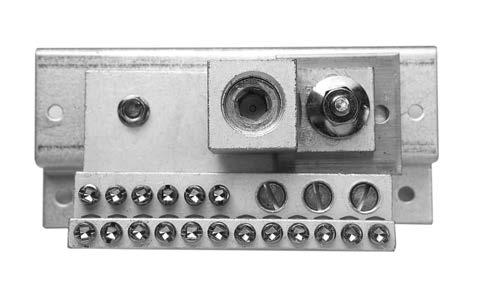
Optional equipment grounds

THQB/THHQB/THQL/THHQL/TEY filler plates

TED4/SE/FB filler plates

Circuit breaker mounting¹ hardware kits

¹ Use to mount circuit breaker in existing space.

² Includes screws, washers and ReliaGear panelboard connectors.

Description Product Number Field installed kits Standard bonded to box-for each 12 branch positions TGL2 Copper bonded to box-for each 12 branch positions TGC2 Standard-isolated/insulated-for each 12 branch positions EGS12 Copper-isolated/insulated-for each 12 branch positions EGC12 Main lug for above terminal kits TGL20
Description Product Number Aluminum Extruded Bonded AEBG Copper Extruded Bonded AEBGC Aluminum Extruded Isolated AEIG Copper Extruded Isolated AEIGC Copper Isolated/Bonded ASPGIBC
Description Product Number Circuit breaker type TED/THED4/SE ASPTED3P Circuit breaker type Formula A2 ASPA23P Circuit breaker type Tmax XT1–for mounting 3 poles ASPXT13P² Circuit breaker type Tmax XT4–for mounting 3 poles ASPXT43P²
Product Number TQLFP1
Product Number TEDFP1
89
AEBG AEBGC AEIG AEIGC ASPGIBC

ReliaGear lighting panelboards

Accessories

Field installed kits/replacement parts

Order by product number from factory

Endwall kits

Field installed. For standard 20"w x 5.81"d boxes.

Panelboard locks

¹ The quarter turn kits are only compatible with factory-built quarter turn fronts. They cannot be used to convert other locks (standard, Corbin, etc.) to quarter turn. Keys are interchangeable with standard, Corbin, etc.

Locking devices

Tmax

Tmax

Tmax

Tmax

Handle Locking (nonpadlocking) Q

Q/E

Corbin
Lock
Handle
locking THL103
Quarter Turn Kit
T-Handle
– PLL —
Fixed padlock in the open position
Product Number Description Qty. ABEW2 Blank 1 AKEW2 Knockout 1
Description Product Number T-Handle Quarter Turn Kit¹ ASPQTRT Flush Quarter Turn Kit¹ ASPQTRK Replacement Lock with Std. Key 569B737P1 Additional Keys for Above Lock 569B737P5 Yale Lock Kit ASPYALE47 Corbin Lock Kit ASPCORBNTEU1 Replacement Lock with ABB75 Key 569B737P2
Replacement Lock with ABB75 Key – Red Replacement Lock with Standard Key – Black
in the open position – PLC
Padlock
Frame Style Description Product Number Padlocking Device (single padlock) Q THQB, THHQB, THQL, THHQL THP100 E TEY TEYPLD1 Formula Formula A2 3 pole KA2LD
Formua A2 2 poleKA2LDOR
Formula
XT XT1 KXTBPLLOPCL
XT XT2 and XT4
KXTCPLLOPCL
XT XT5
KXT5PLLOPLC
XT XT6
KXT6PLLOPLC
THQB,
THHQL THL103
TEY TEYLD1
THHQB, THL,
E
Filler plate for Q and TEY breakers TQLFP1
ACHK
Safety catch for trough covers
AGSK 90
Gasketing Kit

ReliaGear lighting panelboards

Accessories

Field installed kits/replacement parts

Order by product number from factory

Panelboards parts

in factory assembled panels—AD panels with Spectra branch circuit breakers.

to ReliaGear box with or without box endwall in place. Extensions can be combined to obtain lengths greater than 18 and 24 inches.

Permanent circuit number kits Product Number Description RQ, RL, RE AD APN48 APN48AD No’s 1-48 APN84 APN84AD No’s 43-84 APN126 APN126AD No’s 85-126
Description Product Number Directory Card 139C5612P3 Circuit Numbering Strips - 1-48 569B806G1 49-84 569B806G2 85-126 569B806G3 Adhesive Backed Lamicoid Nameplate 3/4 in. x 3 in. 315A7190P1 Metal Directory Card Holder 139C5491G1 Directory Card Holder 139C5491P4 Delta Hi-leg Conversion Kit, to Add B-Phase Plug on RL Panels APHBL Bolt on RE/RQ Panels APHBQ NEMA 3R/12 Tamper Proof Tork Screw Kit NEMATRX AD 25 to 65 kAIC Barrier kit ASP25AD65KA² Service Entrance Kit ASPSERENT 2 wire Relay Kit ASP2WRelay RQ/RL/RE Rail Bracket ASPAQLEBKT Front Flush Adjust Kit ASPFLUSHADJ RE Front Mounting Kit 139C5720G3 RQ/RL Front Mounting Kit 139C5720G6 AD Front Mounting Kit 139C5720G9 Front Hinge to Box Mounting Kit 139C5700G6 Front Extension Mounting Kit 139C5700G11 Can of Touch-up Paint 887878A00 ² Included
Box extensions
Box Extensions Covers Only 10 covers per kit. Description Product Number 9" Covers Surface ASPABX09S 9" Covers Flush ASPABX09F 18" Covers Surface ASPABX18S 18" Covers Flush ASPABX18F 64" to 76" Covers Surface ASPABX20S 64" to 76" Covers Flush ASPABX20F Box Width and Depth Box Mounting Box Extension Length (Inches) Box Extension Product Number 20 x 5.81 Flush 9 ABX2509F 18 ABX2518F 24 ABX2524F Surface 9 ABX2509S 18 ABX2518S 24 ABX2524S 31 ABX2531S 37 ABX2537S 43 ABX2543S 49 ABX2549S 55 ABX2555S 64 ABX2564S 76 ABX2576S 30 x 5.81 Flush 18 ABX3518F 24 ABX3524F Surface 18 ABX3518S 24 ABX3524S 30 x 7.81 Flush 18 ABX3718F 24 ABX3724F Surface 18 ABX3718S 24 ABX3724S 91
Bolts

R-Series Panelboards

92

ReliaGear lighting panelboards

Types

Type RL

Service information:

1P, 3W-120/240 Vac

3P, 3W-240 Vac

3P, 4W-240/120 Vac, 208/120 Vac

Fully rated: 65kAIC at 240V

Series rated: 200kAIC at 240V

Main circuit breakers:

100A-THQB, THHQB, TEY

125A-XT1

225A-A2

250A-XT4

400A-XT5

600A-XT5

800A-XT6¹

Main lug: 125-800A

Branch circuit breakers (plug-in): Amperage-15-100A

Poles-1, 2, 3

Types-THQL, THHQL, TXQL

Subfeeds:

Amperage-15-600A

Poles-2, 3

Types- A2, XT1, XT4, XT5

Enclosures

Depth-5.81”

Type RQ

Service information:

1P, 3W-120/240 Vac

3P, 3W-240 Vac

3P, 4W-240/120 Vac, 208/120 Vac

Fully rated: 65kAIC at 240V

Series rated: 200kAIC at 240V

Main circuit breakers:

100A-THQB, THHQB, TEY

125A-XT1

225A-A2

250A-XT4

400A-XT5

600A-XT5

800A-XT6¹

Main lug:

125-800A

Branch circuit breakers (bolt-on):

Amperage-15-100A

Poles-1, 2, 3

Types-THQB, THHQB, TXQB

Subfeeds:

Amperage-15-600A

Poles-2, 3

Types- A2, XT1, XT4, XT5

Enclosures

Length-25.5, 31.5, 37.5, 43.5, 49.5, 55.5, 64.5, 76.5, 82.5, 88.5

Width-20”

Depth-5.81”

49.5, 55.5, 64.5, 76.5, 82.5, 88.5 Width-20”
Length-25.5, 31.5, 37.5, 43.5,
Type RL Type RQ 93

ReliaGear lighting panelboards

Types

Type RE

Service information:

1P, 3W-120/240 Vac, 125/250 Vdc

3P, 3W-240 Vac

3P, 4W-480/277 Vac, 208/120 Vac, 240/120 Vac

Fully rated: 18kAIC at 480Y/277V, 65kAIC at 240V

Series rated: Reference panel configuration in empower or DET-008

Main circuit breakers:

100A-TEY, TEYF

125A-XT1

250A-XT4

400A-XT5

600A-XT5

800A-XT6¹

Main lug: 125-800A

Branch circuit breakers (bolt-on): Amperage-15-100A

Poles-1, 2, 3

Types-TEY, TEYF

Subfeeds: Amperage-15-600A

Poles: 3*

Types: XT1, XT4, XT5

*3 poles can be used as 2 poles

Enclosures

Width-20”

Depth-5.81”

Type RS

Service information:

1P, 3W-120/240 Vac, 125/250 Vdc

3P, 3W-240 Vac

3P, 4W-480/277 Vac, 208/120 Vac, 240/120 Vac

Fully rated: 65kAIC at 480Y/277V, 100kAIC at 240V

Series rated: Reference panel configuration in empower or DET-008

Main circuit breakers:

100A-TEYD, TEYH, TEYL

125A-XT1

250A-XT4

400A-XT5

600A-XT5

800A-XT6¹

Main lug: 125-800A

Branch circuit breakers (bolt-on):

Amperage-15-125A

Poles- 1, 2, 3

Types- TEYD, TEYH, TEYL

Subfeeds:

Amperage-15-600A

Poles: 3*

Types: XT1, XT4, XT5

*3 poles can be used as 2 poles

Enclosures

Length-25.5,

Width-20”

Depth-5.81”

Type RD

Service information:

3P, 3W-480 Vac, 600 Vac

3P, 4W-208/120 Vac, 480/277 Vac, 600/347 Vac

Fully rated: 42kAIC at 240V, 42 kAIC at 600Y/347V, 42kAIC at 480V

Series rated: Reference panel configuration in empower or DET-008

Main circuit breakers:

150A-XT4

225A-XT4

400A-XT5

600A-XT5

Main lug:

150-800A

Branch circuit breakers (bolt-on):

Amperage-5-100A (FB 1P, 2P)

15-125A (XT2 eKIP DIP Hi-Touch 3P)

220A Max. double branch

Types: FB, XT2 eKIP DIP Hi-Touch

Enclosures

Width-20”

31.5, 37.5, 43.5, 49.5, 55.5, 64.5, 76.5, 82.5, 88.5
Length-25.5,
31.5, 37.5, 43.5, 49.5, 55.5, 64.5, 76.5, 82.5, 88.5
Length-31.5, 37.5, 43.5, 49.5, 55.5, 64.5, 76.5, 82.5, 88.5
RE Type RS Type RD 94
Depth-5.81” Type
95
ReliGear neXT Power Panelboards

Interiors

ReliaGear neXT panelboard interiors feature plug-in and bolt-on (when vertical main circuit breakers are selected) technology, IP 20 “ finger-safe” features (on clean bus only) and center or offset mounting positions within the enclosure. Main lug, feedthrough lug and clean bus options exist. X-height or X-space refers to the space occupied by individual (plug-in) components on the interior bus. One X-space for ReliaGear neXT equals 1.385 inches.

Standard interior heights

• 16X05

• 24X05

• 32X05

• 40X05

Interior materials

• Tin- and silver-plated aluminum (heat rated)

• Tin- and silver-plated copper (heat rated or 1000 A per sq. in. density rated)

30" wide circuit breaker panel Center-mounted interior 40" wide circuit breaker panel Offset-mounted interior 45" wide circuit breaker panel Offset-mounted interior 45" wide circuit breaker panel Center-mounted interior
Typical standard, hinged gutter covers
Typical sheet metal fillers cover the space between gutter covers and circuit breakers/blanks
Typical sheet metal blanks cover the future space for adding circuit breakers to the interior
01
02
03
XT4 XT4 XT4 XT4 XT4 XT4 XT1 XT1 XT1 XT1 XT1 XT1 FB/TEYFB/TEY 225 A04 225 A04 5.5" 5.5" 30" XT4 XT4 XT4 XT4 XT4 XT4 XT5 XT5 XT1 XT1 XT1
8" 5.5" 40" 600 A04 225 A04 XT4 XT4 XT4 XT4 XT4 XT5 XT6/XT7 XT1 XT1 XT1 FB FB/TEY 13" 5.5" 45" 03 02 01 1200 A04 225 A04 XT4 XT4 XT4 XT4 FB/TEY 600 A04 XT5 600 A04 XT5 XT5 XT1 XT4 XT4 FB/TEY 5.5" 5.5" 45" Clean bus Main lug Feed-through lug 04 Maximum ampacity circuit breaker allowed per this side of interior 05 Interiors are double sided; double standard interior heights for available mounting space (Ex. 16X bus has 32X max. of circuit breaker mounting space) 96
FB/TEYFB/TEY

X-space requirements for plug-in devices

X-space requirements for plug-in devices

See table below for the X-space requirements of plug-in components.

XT1 circuit breaker assemblies — panelboard densitiy and mounting hardware

The small footprint of XT1 allows this panel to offer multiple options to improve circuit breaker density. As you configure and order ReliaGear neXT panelboards, you'll notice that XT1 are grouped in quantities of one, two or five. As part of this feature, unique mounting brackets are required when adding XT1 breaker assemblies to existing installations. See below for X-space and mounting brackets required.

Frame Max. ampacity (A) Poles X-space Single XT1 125 3 3 Two XT1 125 3 5 Five XT1 125 3 11 XT4 250 3 3 XT5 600 3 4 XT6 800 3 6 XT7 1200 3 6 FB/TEY 100/70 1 1 FB/TEY 100/125 2 2 SPD – – 10 RELT – – 3 AMP1 main meter – – 4 3 X-spaces 5 X-spaces 11 X-spaces Single XT1 Two XT1 = 16% space saving Five XT1 = 26% space saving
Frame X-space % X-space savings (compared to single XT1 kits) Mounting hardware Single XT1 3 – SR1XBF Two XT1 5 16% SR2XBF Five XT1 11 26% SR5XBF XT1 group
but are sold separately when adding an XT1 to an existing
97
mounting brackets are included in panelboard orders from the factory,
installation.

Stocked Breakers

Select horizontal main and feeder circuit breakers (80% rated only)

US PN Global ABB PN Frame Br Cap @480V X Space Poles Amps Trip Unit Phase XT1HU3015AYD000XXX (1) 1SDX051540R1 (1) XT1 H (65kA) 3 3 15 TMF XT1HU3020AYD000XXX (1) 1SDX051541R1 (1) XT1 H (65kA) 3 3 20 TMF XT1HU3030AYD000XXX (1) 1SDX051543R1 (1) XT1 H (65kA) 3 3 30 TMF XT1HU3040AYD000XXX (1) 1SDX051545R1 (1) XT1 H (65kA) 3 3 40 TMF XT1HU3050AYD000XXX (1) 1SDX051547R1 (1) XT1 H (65kA) 3 3 50 TMF XT1HU3060AYD000XXX (1) 1SDX051548R1 (1) XT1 H (65kA) 3 3 60 TMF XT1HU3070AYD000XXX (1) 1SDX051549R1 (1) XT1 H (65kA) 3 3 70 TMF XT1HU3100AYD000XXX (1) 1SDX051552R1 (1) XT1 H (65kA) 3 3 100 TMF XT1HU3125AYD000XXX (1) 1SDX051554R1 (1) XT1 H (65kA) 3 3 125 TMF XT4HU3060EYG000XXX 1SDX051596R1 XT4 H (65kA) 3 3 60 Ekip LS/I XT4HU3100EYJ000XXX 1SDX051607R1 XT4 H (65kA) 3 3 100 Ekip LS/I XT4HU3150EYJ000XXX 1SDX051617R1 XT4 H (65kA) 3 3 150 Ekip LS/I XT4HU3225EYJ000XXX 1SDX051627R1 XT4 H (65kA) 3 3 225 Ekip LS/I XT4HU3250EYL000XXX 1SDX051633R1 XT4 H (65kA) 3 3 250 Ekip LS/I XT5HU330ABYN000XXX 1SDX052064R1 XT5 H (65kA) 4 3 300 TMA XT5HU340ABYN000XXX 1SDX052069R1 XT5 H (65kA) 4 3 400 TMA XT5HU350BBYN000XXX 1SDX052074R1 XT5 H (65kA) 4 3 500 TMA XT5HU360BBYN000XXX 1SDX052075R1 XT5 H (65kA) 4 3 600 TMA XT7HU380CFYW000XXX 1SDX052323R1 XT7 H (65kA) 6 3 800 Ekip Dip LSI XT7HU310DFYW000XXX 1SDX052353R1 XT7 H (65kA) 6 3 1000 Ekip Dip LSI XT7HU312EFYW000XXX 1SDX052383R1 XT7 H (65kA) 6 3 1200 Ekip Dip LSI NEFBN16TE020R2A 1SQA001023R0001 FB 1pN (65kA) 1 1 20 TMF A NEFBN16TE030R2A 1SQA001035R0001 FB 1pN (65kA) 1 1 30 TMF A NEFBN16TE020R2B 1SQA001098R0001 FB 1pN (65kA) 1 1 20 TMF B NEFBN16TE030R2B 1SQA001104R0001 FB 1pN (65kA) 1 1 30 TMF B NEFBN16TE020R2C 1SQA001137R0001 FB 1pN (65kA) 1 1 20 TMF C NEFBN16TE030R2C 1SQA001143R0001 FB 1pN (65kA) 1 1 30 TMF C NEFBN26TE020R2AB 1SQA001026R0001 FB 2pN (65kA) 2 2 20 TMF AB NEFBN26TE030R2AB 1SQA001038R0001 FB 2pN (65kA) 2 2 30 TMF AB NEFBN26TE040R2AB 1SQA001050R0001 FB 2pN (65kA) 2 2 40 TMF AB NEFBN26TE050R2AB 1SQA001062R0001 FB 2pN (65kA) 2 2 50 TMF AB NEFBN26TE060R2AB 1SQA001068R0001 FB 2pN (65kA) 2 2 60 TMF AB NEFBN26TE100R2AB 1SQA001092R0001 FB 2pN (65kA) 2 2 100 TMF AB NEFBN26TE020R2BC 1SQA001176R0001 FB 2pN (65kA) 2 2 20 TMF BC NEFBN26TE030R2BC 1SQA001182R0001 FB 2pN (65kA) 2 2 30 TMF BC NEFBN26TE040R2BC 1SQA001188R0001 FB 2pN (65kA) 2 2 40 TMF BC NEFBN26TE050R2BC 1SQA001194R0001 FB 2pN (65kA) 2 2 50 TMF BC NEFBN26TE060R2BC 1SQA001197R0001 FB 2pN (65kA) 2 2 60 TMF BC NEFBN26TE100R2BC 1SQA001209R0001 FB 2pN (65kA) 2 2 100 TMF BC NEFBN26TE020R2AC 1SQA001215R0001 FB 2pN (65kA) 2 2 20 TMF AC NEFBN26TE030R2AC 1SQA001221R0001 FB 2pN (65kA) 2 2 30 TMF AC NEFBN26TE040R2AC 1SQA001227R0001 FB 2pN (65kA) 2 2 40 TMF AC NEFBN26TE050R2AC 1SQA001233R0001 FB 2pN (65kA) 2 2 50 TMF AC NEFBN26TE060R2AC 1SQA001236R0001 FB 2pN (65kA) 2 2 60 TMF AC NEFBN26TE100R2AC 1SQA001248R0001 FB 2pN (65kA) 2 2 100 TMF AC (1) SR1XBF mounting bracket required for each XT1 ordered 98

S = Ekip Touch Measuring LSIG

T = Ekip Hi-Touch LSI

U = Ekip Hi-Touch LSIG Interrupting rating

Part identifier XT = Circuit breaker family Frame 1 = XT1 4 = XT4 5 = XT5 6 = XT6 7 = XT7 Frame amps 015 = 15 A080 = 80 A 25A = 250A (XT5) 020 = 20 A090 = 90 A 30A = 300 A 025 = 25 A100 = 100 A 40A = 400 A 030 = 30 A110 = 110 A 50B = 500 A 035 = 35 A125 = 125 A 60B = 600 A (XT5) 040 = 40 A150 = 150 A 600 = 600 A (XT6) 045 = 45 A175 = 175 A 80C = 800 A (XT7) 050 = 50 A200 = 200 A 800 = 800 A (XT6) 060 = 60 A225 = 225 A 10E = 1000 A 070 = 70 A250 = 250A (XT4)12E = 1200 A Trip unit
= TMF
= TMA
= Molded Case Switch
= Ekip DIP LS/I
= Ekip
=
— ReliaGear neXT renewal parts catalog numbers XT circuit breakers
A
B
D
E
F
DIP LSI G
Ekip DIP LSIG P = Ekip Touch LSI Q = Ekip Touch LSIG R = Ekip Touch Measuring LSI
N = N S = S H = H L = L V = V kAIC rating depending on voltage level; refer to performance table. Standard U = UL 80% rated Q = UL 100% rated Poles 3 = 3 poles XT Y 1 D N 00 U X 3 X 015 X A X 99

ReliaGear neXT renewal parts catalog numbers

XT circuit breakers (continued)

Line-side terminals (top)

Y = Line-side connectors

Load-side terminal (bottom)

D = XT1 10–2/0 AWG

G = XT4 14–1/0 AWG, 100 A

N = XT5 2x2/0 AWG-500kcmil

U = XT6 3x2/0 AWG-400kcmil

J = XT4 4 AWG– 300 kcmil, 225 AW = XT7 4x4/0 AWG-500kcmil

L = XT4 3/0 AWG–350 kcmil, 250 AX = XT7 3x500-750kcmil

Additional certifications

X = None

Advanced functionalities

X = None

Key locks

X = None

A = Ronis key lock – A type key

K = Castell key lock XT5-XT7 Accessories

E = Ronis key lock – Different keys

G = Kirk key lock XT5-XT7
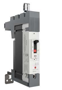
combination 00 = None Aux. Bell alarm Shunt opening release Undervoltage release Communication modules Front accessories 0 = None G = Padlock
XT Y 1 D N 00 U 0 3 X 015 X A X 100
Please refer to Tmax XT technical catalog for more information.

ReliaGear neXT renewal parts catalog numbers

FB circuit breakers

TEY circuit breakers

Part identifier NEFB = neXT FB circuit breakers Part identifier TEYA = neXT TEY circuit breakers Interrupting rating V = V N = N H = H kAIC rating depending on voltage level; refer to performance table. Interrupting rating D = D H = H L = L kAIC rating depending on voltage level; refer to performance table. Rated current 015 = 15 A050 = 50 A 020 = 20 A060 = 60 A 025 = 25 A070 = 70 A 030 = 30 A080 = 80 A 035 = 35 A090 = 90 A 040 = 40 A100 = 100 A 045 = 45 A Phase R2A = A phase (1p) R2B = B phase (1p) R2C = C phase (1p) 2AB = AB phases (2p) 2AC = AC phases (2p) 2BC = BC phases (2p) Phase 0A = A phase (1p)AB = AB phases (2p) 0B = B phase (1p)AC = AC phases (2p) 0C = C phase (1p)BC = BC phases (2p) Load lug A = (1) #14-10. 15-20A B = (1) #10-4. 25-60A C = #4-2/0. 70-125A Shunt trip X = None M = 120V K = 24VN = 240V Aux X = None D = 277V Bell alarm X = NoneA = Bell alarm Other X = None Other X = None PDL X = NoneC = Padlock Poles 1 = 1 pole 2 = 2 poles Poles E = 1 pole F = 2 poles Voltage rating 6 = 600/347 V Rated Current C = 015L = 060 D = 020M = 070 E = 025N = 080 F = 030P = 090 G = 035Q = 100 H = 040R = 110 J = 045S = 125 K = 050 Trip unit TE = Fixed thermal magnetic NEFB V 1 6 TE 015R2A TEYA D ECAXXXXXX 0A 101

Spacers

SR 01 BF

BB

ReliaGear neXT renewal parts catalog numbers
Part identifier SR = Spacer X height 01 = 1"10 = 10" 02 = 2"1X = Single XT1 spacer 03 = 3"2X = Double XT1 spacer 04 = 4"T1 = XT1 06 = 6" Filler
= Blank and filler
BF
=
Blank only
EF = Filler only
RF = RELT filler
SF = SPD filler
102

POWER PANELBOARDS AND SWITCHBOARDS

Tmax ® XT Retrofit Kits for Spectra™ Panelboards

Extending the life of your installation

103

Choosing the right retrofit has never been so easy

You consider what you need. We will show you what's possible

The world of electrical distribution is a complex one, yet choosing the right device for your individual needs has never been simpler thanks to this Tmax ® XT retrofit01 offering for Spectra™ Panelboards and Switchboards. Maybe you are looking for a basic protection device for a standard distribution system.

Or perhaps you need something more complex, such as a locking mechanisms or devices that integrate protection, automation, measuring and communication into a cloud-based supervision system. Follow the flowchart when placing an order. All mounting kits, filler plates and hardware required are included under a single part number. Circuit breakers are ordered separately.02

Step 1. Select breaker and trip unit Step 2. Select retrofit kit Step 3. Enter separate breaker and retrofit kit orders through empower.abb.com using desktop, laptop or mobile devices. ABB empower Step 4. Receive breaker and retrofit kit shipments — 01 Maximum of two Tmax ® XT4, XT5 or XT7 retrofit kits can be installed, side by side, in an existing Spectra™ panelboard installation — 02 For instantaneous selectivity, see DET-760. For series ratings, see DET-008.
Bolt-on Strap Kits - Type SRFB Neutral CT Kits - Type SRFN Example: Example: SRFB SRFN 6 400 Poles Ampere Rating 3 XT1 = Tmax ® XT XT1 XT4 = Tmax ® XT XT4 XT5 = Tmax ® XT XT5 XT7 = Tmax ® XT XT7 GF = Tmax ® XT Spectra™ Panel Neutral CT kit Blank = Main or Branch B = Branch Only M = Main Only FPX = FPK = With Filler Plate Kit (full width plates with cutouts for handles, etc.) With Filler Plate Kit and Kirk Lock Provision 6 C/B Frame Modification Code Mounting Accessory Code XT1 GF B FPX 400 = 400A Tmax ® XT XT5 600 = 600A Tmax ® XT XT5 800 = 800A Tmax ® XT XT7 100 = 1000A Tmax ® XT XT7 120 = 1200A Tmax ® XT XT7 104

Possible combinations within the range Legacy Spectra™ breaker
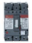
— 02 XT7 breaker handle extension included in this kit
01 Maximum of two Tmax ® XT4, XT5 or XT7 retrofit kits can be installed, side by side, in an existing Spectra panelboard installation
Spectra™ E Frame Spectra™ F Frame Spectra™ G Frame Spectra™ K Frame Tmax ® XT Breaker Tmax ® XT1 Tmax ® XT4 Tmax ® XT5 Tmax ® XT7
and industrial applications
trip units Electronic trip units 125 A 250 A 250 A 600 A 600 A 1200 A Legacy Spectra™ based Kit AMCB6EBFP AMCB6FJFPAMCB3FJFPAMCB6GBFPAMCB3GMFP AMCB3KMFP
®
Kit
SRFB6XT1FPXSRFB6XT4FPXSRFB3XT4FPXSRFB6XT5BFPXSRFB3XT5MFPXSRFB3XT7MFPX 02
®
SRFB6XT1FPKSRFB6XT4FPKSRFB3XT4FPKSRFB6XT5BFPKSRFB3XT5MFPKSRFB3XT7MFPK 02
XT5 UL 400 A Neutral current transformer kit
XT5 UL 600 A Neutral current transformer kit
XT7 UL 800 A Neutral current transformer kit
XT7 UL 1000 A Neutral current transformer kit
XT7 UL 1200 A Neutral current transformer kit 105
Industrial applications Commercial
Thermal-magnetic
Tmax
XT
01
Tmax
XT Kit with Kirk lock provisions 01
SRFN400GF
SRFN600GF
SRFN800GF
SRFN100GF
SRFN120GF

Accessories for Retrofit Kits

The parts you might need for your installation Neutral

XT1
XT4
XT5
XT7
106
Current Transformers for XT5 and XT7
Kirk Lock XT7 folding handle reduces handle operation effort and are included in XT7 retrofit kits
Kirk Lock
Kirk Lock
Kirk Lock

Lighting distribution panelboards

Renewal parts

Mounting hardware

Order from the customer service center

Mounting hardware with filler plate, straps and brackets bolt-on Spectra™ - Mounting kit with filler plate includes hardware straps, brackets and filler plate. - Filler plate kit includes filler plate and associated hardware only.

Please note that Spectra, TED, FE, and FG breakers are obsolete

Mounting Arrangement Breaker Frame Number of Poles Box Width Range X Height Product Number Dual Mounted TEB, TED 2-pole 27"-44" 2X AMCB4EBFP Dual Mounted TEY 2-pole 27"-44" 3X AMCB4EYFP Dual Mounted FBV, FBN, FBH, or FBL 2-pole 27"-44" 2X AMCB4FBFP Dual Mounted FCS, FCV, FCN, FCH or FCL 2-pole 27", 31", 36", 40", 44" 3X AMCB4FDBFP Dual Mounted FES, FEV, FEN, FEH or FEL 2-pole 27", 31", 36", 40", 44" 3X AMCB4FEBFP Dual Mounted TQD, THQD 2-pole 27"-44" 2X AMCB4QDFP Dual Mounted THED, SED, SEH, SEL, SEP 2-pole 27"-44" 3X AMCB4SEFP Dual Mounted TEB, TED, THED, SED, SEH, SEL, SEP 3-pole 27"-44" 3X AMCB6EBFP Dual Mounted XT1 3-pole 27"-44" 3X SRFB6XT1FPX Dual Mounted XT1 3-pole 27"-44" 3X SRFB6XT1FPK Dual Mounted TEY 3-pole 27"-44" 3X AMCB6EYFP Dual Mounted FBV, FBN, FBH, or FBL 3-pole 27"-44" 3X AMCB6FBFP Dual Mounted FCS, FCV, FCN, FCH or FCL 3-pole 27", 31", 36", 40", 44" 3X AMCB6FDBFP Dual Mounted FES, FEV, FEN, FEH or FEL 3-pole 27", 31", 36", 40", 44" 3X AMCB6FEBFP Dual Mounted TQD, THQD 3-pole 27"-44" 3X AMCB6QDFP Dual Mounted SFH, SFL, SFP 2-pole 31"-44" 3X AMCB4FJFP Dual Mounted SFH, SFL, SFP 3-pole 31"-44" 3X AMCB6FJFP Dual Mounted XT4 3-pole 31"-44" 3X SRFB6XT4FPX1 Dual Mounted XT4 3-pole 31"-44" 3X SRFB6XT4FPK1 Dual Mounted TFJ, TFK, THFK 2-pole 36"-44" 2X AMCB4FJFPTF Dual Mounted TFJ, TFK, THFK 3-pole 36"-44" 3X AMCB6FJFPTF Dual Mounted FGV, FGN, FGH or FGP 2-pole 40", 44" 4X AMCB4FGBFP Dual Mounted SGH, SGL, SGP 2-pole 40"-44" 4X AMCB4GBFP Dual Mounted FGV, FGN, FGH or FGP 3-pole 40", 44" 4X AMCB6FGBFP Dual Mounted SGH, SGL, SGP 3-pole 40"-44" 4X AMCB6GBFP Dual Mounted XT5 3-pole 40"-44" 4X SRFB6XT5BFPX1 Dual Mounted XT5 3-pole 40"-44" 4X SRFB6XT5BFPK1 Single Mounted SFH, SFL, SFP 2-pole 27"-44" 3X AMCB2FJFP Single Mounted TFJ, TFK, THFK 2-pole 27"-44" 3X AMCB2FJFPTF Single Mounted FGV, FGN, FGH or FGP 2-pole 27", 31", 36", 40", 44" 4X AMCB2FGMFP Single Mounted FES, FEV, FEN, FEH or FEL 2-pole 27", 31", 36", 40", 44" 3X AMCB2FEBFP Single Mounted SGH, SGL, SGP 2-pole 27"-44" 4X AMCB2GMFP Single Mounted SFH, SFL, SFP 3-pole 27"-44" 3X AMCB3FJFP Single Mounted XT4 3-pole 27"-44" 3X SRFB3XT4FPX1 Single Mounted XT4 3-pole 27"-44" 3X SRFB3XT4FPK1 Single Mounted TFJ, TFK, THFK 3-pole 27"-44" 3X AMCB3FJFPTF Single Mounted FGV, FGN, FGH or FGP 3-pole 27", 31", 36", 40", 44" 4X AMCB3FGMFP Single Mounted FES, FEV, FEN, FEH or FEL 3-pole 27", 31", 36", 40", 44" 3X AMCB3FEBFP Single Mounted SGH, SGL, SGP 3-pole 27"-44" 4X AMCB3GMFP Single Mounted XT5 3-pole 27"-44" 4X SRFB3XT5MFPX1 Single Mounted XT5 3-pole 27"-44" 4X SRFB3XT5MFPK1 Single Mounted SKP 2-pole 27"-44" 6X AMCB3LBFP Single Mounted SKH, SKL, SKP, TKM, THKM 2-pole 40"-44" 6X AMCB2KMFP Single Mounted SKH, SKL, SKP, TKM, THKM 3-pole 40"-44" 6X AMCB3KMFP Single Mounted XT7 3-pole 40"-44" 6X SRFB3XT7MFPX1 Single Mounted XT7 3-pole 40"-44" 6X SRFB3XT7MFPK1 1Maximum of two XT4, XT5, XT7 kits may be stacked beside each other.
107

Lighting distribution panelboards

Renewal parts

Mounting hardware

Order from the customer service center

Filler plates bolt-on Spectra™

- Filler plate kit includes filler plate and associated hardware only.

Notes: 1X = 1 3/8" vertical space. THLC 1/2/4 breaker no longer available.

Filler plates plug-in or bolt-on Spectra™

Use to cover unused spaces.

Includes filler plate support brackets and hardware.

Please note that Spectra, TED, FE, and FG breakers are obsolete

Space X Height1 Box Width Range Switchboard Section Widths Product Number 1X 27", 31" 35 APP1S 2X 27", 31" 35 APP2S 3X 27", 31" 35 APP3S 4X 27", 31" 35 APP4S 5X 27", 31" 35 APP5S 6X 27", 31" 35 APP6S 1X 36", 40" 40 APP1 2X 36", 40" 40 APP2 3X 36", 40" 40 APP3 4X 36", 40" 40 APP4 5X 36", 40" 40 APP5 6X 36", 40" 40 APP6 1X 44" 45 APP1W 2X 44" 45 APP2W 3X 44" 45 APP3W 4X 44" 45 APP4W 5X 44" 45 APP5W 6X 44" 45 APP6W 1X-height: 1X = 1 3/8"
Mounting Arrangement Breaker Frame Number of Poles Box Width Range X Height Product Number Dual Mounted TQD, THQD 2-pole 27"-44" 2X AFP2QDD Dual Mounted TEB, TED 2-pole 27"-44" 2X AFP2TED Dual Mounted TEY 2-, 3-pole 27"-44" 3X AFP3EYD Dual Mounted FBV, FBN, FBH, or FBL 2-pole 27"-44" 2X AFP2FBD Dual Mounted FBV, FBN, FBH, or FBL 3-pole 27"-44" 3X AFP3FBD Dual Mounted TQD, THQD 3-pole 27"-44" 3X AFP3QDD Dual Mounted TEB, TED, THED,SED, SEH, SEL, SEP 2-, 3-pole 27"-44" 3X AFP3SED Dual Mounted SFH, SFL, SFP 2-, 3-pole 31"-44" 3X AFP3SFD Dual Mounted TFJ, TFK, THFK 2-, 3-pole 36"-44" 2X, 3X AFP3TFD Dual Mounted FGV, FGN, FGH or FGP 3-pole 40",44" 4X AFP4FGD Dual Mounted SGH, SGL, SGP 2-, 3-pole 40"-44" 4X AFP4SGD Single Mounted SFH, SFL, SFP 2-, 3-pole 27"-44" 3X AFP3SFS Single Mounted TFJ, TFK, THFK 2-, 3-pole 27"-44" 3X AFP3TFS Single Mounted FGV, FGN, FGH or FGP 2-, 3-pole 27", 31", 36", 40", 44" 4X AFP4FGS Single Mounted SGH, SGL, SGP 2-, 3-pole 27"-44" 4X AFP4SGS Single Mounted SKP 2-pole 27"-44" 6X AFP5LCS Single Mounted SKP, SKH, SKL, TKM, THKM 3-pole 44"-44" 6X AFP6SKS
108

Molded Case Circuit Breakers

109

Q-Line Circuit Breakers

Bolt-on Circuit Breakers

240V Class

TQB, THQB 240 Vac, Internal Common Trip

THQB 120/240
# of Poles Ampere Rating Wire Range1 120/240 Vac Interrupting Rating Product Number 1 10 14-8 Cu/12-8 Al 5kA TQB11103 1 15 14-8 Cu/12-8 Al 10kA THQB11152 1 20 14-8 Cu/12-8 Al 10kA THQB11202 1 25 14-8 Cu/12-8 Al 10kA THQB1125 1 30 14-8 Cu/12-8 Al 10kA THQB1130 1 35 8-3 Cu/8-3 Al 10kA THQB1135 1 40 8-3 Cu/8-3 Al 10kA THQB1140 1 45 8-3 Cu/8-3 Al 10kA THQB1145 1 50 8-3 Cu/8-3 Al 10kA THQB1150 1 60 8-3 Cu/8-3 Al 10kA THQB1160 1 70 6-1/0 Cu/4-1/0 Al 10kA THQB1170
TQB,
Vac
# of Poles Ampere Rating Wire Range1 120/240 Vac Interrupting Rating Product Number 2 10 14-8 Cu/12-8 Al 5kA TQB21103 2 15 14-8 Cu/12-8 Al 10kA THQB2115 2 20 14-8 Cu/12-8 Al 10kA THQB2120 2 25 14-8 Cu/12-8 Al 10kA THQB2125 2 30 14-8 Cu/12-8 Al 10kA THQB2130 2 35 8-3 Cu/8-3 Al 10kA THQB2135 2 40 8-3 Cu/8-3 Al 10kA THQB2140 2 45 8-3 Cu/8-3 Al 10kA THQB2145 2 50 8-3 Cu/8-3 Al 10kA THQB2150 2 60 8-3 Cu/8-3 Al 10kA THQB2160 2 70 6-1/0 Cu/4-1/0 Al 10kA THQB2170 2 80 6-1/0 Cu/4-1/0 Al 10kA THQB2180 2 90 6-1/0 Cu/4-1/0 Al 10kA THQB2190 2 100 6-1/0 Cu/4-1/0 Al 10kA THQB21100
TQB,
THQB 120/240 Vac, Internal Common Trip
# of Poles Ampere Rating Wire Range1 240 Vac Interrupting Rating Product Number 2 10 14-8 Cu/12-8 Al 5kA TQB220103 2 15 14-8 Cu/12-8 Al 10kA THQB22015 2 20 14-8 Cu/12-8 Al 10kA THQB22020 2 25 14-8 Cu/12-8 Al 10kA THQB22025 2 30 14-8 Cu/12-8 Al 10kA THQB22030 2 35 8-3 Cu/8-3 Al 10kA THQB22035 2 40 8-3 Cu/8-3 Al 10kA THQB22040 2 45 8-3 Cu/8-3 Al 10kA THQB22045 2 50 8-3 Cu/8-3 Al 10kA THQB22050 2 60 8-3 Cu/8-3 Al 10kA THQB22060 2 70 6-1/0 Cu/4-1/0 Al 10kA THQB22070 2 80 6-1/0 Cu/4-1/0 Al 10kA THQB22080 2 90 6-1/0 Cu/4-1/0 Al 10kA THQB22090 2 100 6-1/0 Cu/4-1/0 Al 10kA THQB22100 3 10 14-8 Cu/12-8 Al 5kA TQB320103 3 15 14-8 Cu/12-8 Al 10kA THQB32015 3 20 14-8 Cu/12-8 Al 10kA THQB32020 3 25 14-8 Cu/12-8 Al 10kA THQB32025 3 30 14-8 Cu/12-8 Al 10kA THQB32030 3 35 8-3 Cu/8-3 Al 10kA THQB32035 3 40 8-3 Cu/8-3 Al 10kA THQB32040 3 45 8-3 Cu/8-3 Al 10kA THQB32045 3 50 8-3 Cu/8-3 Al 10kA THQB32050 3 60 8-3 Cu/8-3 Al 10kA THQB32060 3 70 6-1/0 Cu/4-1/0 Al 10kA THQB32070 3 80 6-1/0 Cu/4-1/0 Al 10kA THQB32080 3 90 6-1/0 Cu/4-1/0 Al 10kA THQB32090 3 100 6-1/0 Cu/4-1/0 Al 10kA THQB32100 1Solid or stranded for 14-10 AWG. 2UL listed as SWD (Switching Duty) rated. Suitable for switching 120 Vac fluorescent lighting loads. 3Not UL listed. UL listed HACR (heating, air conditioning and refrigeration).
110
THQB2115

Q-Line Circuit Breakers

Bolt-on Circuit Breakers

240V Class

# of Poles Ampere Rating Wire Range1 120/240 Vac Interrupting Rating Product Number 1 15 14-10 Cu/14-10 Al 10kA THQB1115AF22 1 20 14-10 Cu/14-10 Al 10kA THQB1120AF22 1 15 14-10 Cu/14-10 Al 22kA THHQB1115AF22 1 20 14-10 Cu/14-10 Al 22kA THHQB1120AF22
THQB and THHQB 120/240 Vac Arc Fault (Single pole)
120 Vac, Ground Fault Circuit Interrupters (30 ma); cULus # of Poles Ampere Rating Wire Range1 120 Vac Interrupting Rating Product Number 1 15 14-8 Cu/12-8 Al 10kA THQB1115GFEP 1 20 14-8 Cu/12-8 Al 10kA THQB1120GFEP 1 30 14-8 Cu/12-8 Al 10kA THQB1130GFEP
THQB
Interrupters, Internal Common Trip # of Poles Ampere Rating Wire Range1 120 Vac Interrupting Rating Product Number 2 15 14-8 Cu/12-8 Al 22kA THHQB2115GFEP 2 20 14-8 Cu/12-8 Al 22kA THHQB2120GFEP 2 30 14-8 Cu/12-8 Al 22kA THHQB2130GFEP
THHQB 120 Vac, Ground Fault Circuit
cULus Internal Common Trip # of Poles Ampere Rating Wire Range1 120 Vac Interrupting Rating Product Number 2 15 14-8 Cu/12-8 Al 10kA THQB2115GFEP 2 20 14-8 Cu/12-8 Al 10kA THQB2120GFEP 2 30 14-8 Cu/12-8 Al 10kA THQB2130GFEP 2 40 14-8 Cu/12-8 Al 10kA THQB2140GFEP 1Solid or stranded for 14-10 AWG. 2Combination AFCI compliant with NEC 2008 and later. THQB, THHQB 120/240 Vac, Ground Fault Circuit Interrupters, Self Testing, cULus # of Poles Ampere Rating Wire Range1 120/240 Vac Interrupting Rating Product Number 1 15 14-8Cu/12-8 Al 10kA THQB1115GFT 1 20 14-8Cu/12-8 Al 10kA THQB1120GFT 1 25 14-8 Cu/12-8 Al 10kA THQB1125GFT 1 30 14-8Cu/12-8 Al 10kA THQB1130GFT 1 15 14-8Cu/12-8 Al 22kA THHQB1115GFT 1 20 14-8Cu/12-8 Al 22kA THHQB1120GFT 1 25 14-8 Cu/12-8 Al 22kA THHQB1125GFT 1 30 14-8Cu/12-8 Al 22kA THHQB1130GFT 2 15 14-8Cu/12-8 Al 10kA THQB2115GFT 2 20 14-8Cu/12-8 Al 10kA THQB2120GFT 2 25 14-8 Cu/12-8 Al 10kA THQB2125GFT 2 30 14-8Cu/12-8 Al 10kA THQB2130GFT 2 15 14-8Cu/12-8 Al 22kA THHQB2115GFT 2 20 14-8Cu/12-8 Al 22kA THHQB2120GFT 2 25 14-8Cu/12-8 Al 22kA THHQB2125GFT 2 30 14-8Cu/12-8 Al 22kA THHQB2130GFT
THQB
120/240 or 208Y/120 Vac, Ground Fault Circuit Interrupters (30 ma);
THQB1120AF2 THQB2120GFT THQB1115GFEP
111
THQB2140GFEP

Q-Line Circuit Breakers

Bolt-on Circuit Breakers

240V Class THQB,

THHQB 120/240 Vac, High Intensity Discharge Lighting Loads1 # of Poles Ampere Rating Wire Range2 120/240 Vac Interrupting Rating Product Number 1 15 14-8 Cu/12-8 Al 10kA THQB1115HID3 1 20 14-8 Cu/12-8 Al 10kA THQB1120HID3 1 25 14-8 Cu/12-8 Al 10kA THQB1125HID 1 30 14-8 Cu/12-8 Al 10kA THQB1130HID 1 15 14-8 Cu/12-8 Al 22kA THHQB1115HID3 1 20 14-8 Cu/12-8 Al 22kA THHQB1120HID3 1 25 14-8 Cu/12-8 Al 22kA THHQB1125HID 1 30 14-8 Cu/12-8 Al 22kA THHQB1130HID 2 15 14-8 Cu/12-8 Al 10kA THQB2115HID 2 20 14-8 Cu/12-8 Al 10kA THQB2120HID 2 25 14-8 Cu/12-8 Al 10kA THQB2125HID 2 30 14-8 Cu/12-8 Al 10kA THQB2130HID
120 Vac, Internal Common Trip with Factory Installed 120 Vac Shunt Trip4 # of Poles Ampere Rating Wire Range2 120 Vac Interrupting Rating Product Number 2 20 14-8 Cu/12-8 Al 10kA THQB2120ST1 2 30 14-8 Cu/12-8 Al 10kA THQB2130ST1 2 100 6-1/0 Cu/4-1/0 Al 10kA THQB21100ST1 3 20 14-8 Cu/12-8 Al 10kA THQB32020ST1 3 30 14-8 Cu/12-8 Al 10kA THQB32030ST1 3 35 8-3 Cu/8-3 Al 10kA THQB32035ST1 3 40 8-3 Cu/8-3 Al 10kA THQB32040ST1 3 50 8-3 Cu/8-3 Al 10kA THQB32050ST1 3 60 8-3 Cu/8-3 Al 10kA THQB32060ST1 3 70 6-1/0 Cu/4-1/0 Al 10kA THQB32070ST1 3 80 6-1/0 Cu/4-1/0 Al 10kA THQB32080ST1 3 90 6-1/0 Cu/4-1/0 Al 10kA THQB32090ST1 3 100 6-1/0 Cu/4-1/0 Al 10kA THQB32100ST1 THHQB 120/240 Vac, Internal Common Trip, High Intensity Discharge Lighting Loads1 # of Poles Ampere Rating Wire Range2 120/240 Vac Interrupting Rating Product Number 2 15 14-8 Cu/12-8 Al 22kA THHQB2115HID 2 20 14-8 Cu/12-8 Al 22kA THHQB2120HID 2 25 14-8 Cu/12-8 Al 22kA THHQB2125HID 2 30 14-8 Cu/12-8 Al 22kA THHQB2130HID THQB 120 Vac with Switching Neutral Single Thermal Magnetic Pole; Single Nonautomatic Pole # of Poles Ampere Rating Wire Range2 120 Vac Interrupting Rating Product Number 2 15 14-8 Cu/12-8 Al 10kA THQB21WY15 2 20 14-8 Cu/12-8 Al 10kA THQB21WY20 2 25 14-8 Cu/12-8 Al 10kA THQB21WY25 2 30 14-8 Cu/12-8 Al 10kA THQB21WY30 THQB 120 Vac with Switching Neutral Two Thermal Magnetic Pole; Single Nonautomatic Pole # of Poles Ampere Rating Wire Range2 120 Vac Interrupting Rating Product Number 3 15 14-8 Cu/12-8 Al 10kA THQB31WY15 3 20 14-8 Cu/12-8 Al 10kA THQB31WY20 3 25 14-8 Cu/12-8 Al 10kA THQB31WY25 3 30 14-8 Cu/12-8 Al 10kA THQB31WY30 1UL listed as HID (high intensity discharge). 2Solid or stranded for 14-10 AWG. 3UL listed as SWD (switching duty). Suitable for switching 120 Vac fluorescent lighting loads. 420-60 ampere are UL listed as HACR (heating, air conditioning and refrigeration). THQB 120 Vac with Factory Installed 120 Vac Shunt Trip4 # of Poles Ampere Rating Wire Range2 120 Vac Interrupting Rating Product Number 1 20 14-8 Cu/12-8 Al 10kA THQB1120ST1
THQB
112
THQB32020ST1

Q-Line Circuit Breakers

120/240 Vac # of Poles Ampere Rating Wire Range1 120/240 Vac Interrupting Rating Product Number 1 15 14-8 Cu/12-8 Al 22kA THHQB11152 1 20 14-8 Cu/12-8 Al 22kA THHQB11202 1 25 14-8 Cu/12-8 Al 22kA THHQB1125 1 30 14-8 Cu/12-8 Al 22kA THHQB1130 1 35 8-3 Cu/8-3 Al 22kA THHQB1135 1 40 8-3 Cu/8-3 Al 22kA THHQB1140 1 45 8-3 Cu/8-3 Al 22kA THHQB1145 1 50 8-3 Cu/8-3 Al 22kA THHQB1150 1 60 8-3 Cu/8-3 Al 22kA THHQB1160 1 70 6-1/0 Cu/4-1/0 Al 22kA THHQB1170 THQB/THHQB 120/240 Vac, Low Magnetic Pickup # of Poles Ampere Rating Wire Range1 120/240 Vac Interrupting Rating Product Number 1 15 14-8 Cu/12-8 Al 10 kA THQB1115LM2 1 20 14-8 Cu/12-8 Al 10 kA THQB1120LM2 1 15 14-8 Cu/12-8 Al 22 kA THHQB1115LM 1 20 14-8 Cu/12-8 Al 22 kA THHQB1120LM 2 15 14-8 Cu/12-8 Al 10 kA THQB2115LM 2 20 14-8 Cu/12-8 Al 10 kA THQB2120LM 2 15 14-8 Cu/12-8 Al 22 kA THHQB2115LM 2 20 14-8 Cu/12-8 Al 22 kA THHQB2120LM
Bolt-on Circuit Breakers 240V Class THHQB
120/240 Vac, Internal Common Trip # of Poles Ampere Rating Wire Range1 120/240 Vac Interrupting Rating Product Number 2 15 14-8 Cu/12-8 Al 22kA THHQB2115 2 20 14-8 Cu/12-8 Al 22kA THHQB2120 2 25 14-8 Cu/12-8 Al 22kA THHQB2125 2 30 14-8 Cu/12-8 Al 22kA THHQB2130 2 35 8-3 Cu/8-3 Al 22kA THHQB2135 2 40 8-3 Cu/8-3 Al 22kA THHQB2140 2 45 8-3 Cu/8-3 Al 22kA THHQB2145 2 50 8-3 Cu/8-3 Al 22kA THHQB2150 2 60 8-3 Cu/8-3 Al 22kA THHQB2160 2 70 6-1/0 Cu/4-1/0 Al 22kA THHQB2170 2 80 6-1/0 Cu/4-1/0 Al 22kA THHQB2180 2 90 6-1/0 Cu/4-1/0 Al 22kA THHQB2190 2 100 6-1/0 Cu/4-1/0 Al 22kA THHQB21100 THHQB 120/240 Vac, Internal Common Trip # of Poles Ampere Rating Wire Range1 240 Vac Interrupting Rating Product Number 2 15 14-8 Cu/12-8 Al 22kA THHQB22015 2 20 14-8 Cu/12-8 Al 22kA THHQB22020 2 25 14-8 Cu/12-8 Al 22kA THHQB22025 2 30 14-8 Cu/12-8 Al 22kA THHQB22030 2 35 8-3 Cu/8-3 Al 22kA THHQB22035 2 40 8-3 Cu/8-3 Al 22kA THHQB22040 2 45 8-3 Cu/8-3 Al 22kA THHQB22045 2 50 8-3 Cu/8-3 Al 22kA THHQB22050 2 60 8-3 Cu/8-3 Al 22kA THHQB22060 2 70 6-1/0 Cu/4-1/0 Al 22kA THHQB22070 2 80 6-1/0 Cu/4-1/0 Al 22kA THHQB22080 2 90 6-1/0 Cu/4-1/0 Al 22kA THHQB22090 2 100 6-1/0 Cu/4-1/0 Al 22kA THHQB22100 3 15 14-8 Cu/12-8 Al 22kA THHQB32015 3 20 14-8 Cu/12-8 Al 22kA THHQB32020 3 25 14-8 Cu/12-8 Al 22kA THHQB32025 3 30 14-8 Cu/12-8 Al 22kA THHQB32030 3 35 8-3 Cu/8-3 Al 22kA THHQB32035 3 40 8-3 Cu/8-3 Al 22kA THHQB32040 3 45 8-3 Cu/8-3 Al 22kA THHQB32045 3 50 8-3 Cu/8-3 Al 22kA THHQB32050 3 60 8-3 Cu/8-3 Al 22kA THHQB32060 3 70 6-1/0 Cu/4-1/0 Al 22kA THHQB32070 3 80 6-1/0 Cu/4-1/0 Al 22kA THHQB32080 3 90 6-1/0 Cu/4-1/0 Al 22kA THHQB32090 3 100 6-1/0 Cu/4-1/0 Al 22kA THHQB32100 1Solid or stranded for 14-10 AWG. 2UL listed as SWD (switching duty) rated. Suitable for switching 120 Vac fluorescent lighting loads. UL listed HACR (heating, air conditioning and refrigeration). 113
THHQB

Industrial Circuit Breakers

15-100A

Thermal Magnetic Trip

Type TEY/TEYF

Noninterchangeable Trip

Bolt-on

480Y/277V Class

TEY and TEYF breakers are one-inch wide per pole, compact, bolt-on circuit breakers for use on grounded 480Y/277 Vac systems. Short circuit ratings at that voltage for TEY and TEYF are 14 and 18kA, respectively. TEYF also offers higher selectivity ratings with upstream devices (See DET-537 for details). The bolt-on mounting base (TEY3B) shown on page 6-217 makes TEY and TEYF suitable for various lug-lug applications.

TEY/TEYF (UL/cUL File E-11592)

1Solid or stranded for 14-10 AWG.

2Single-pole, 15 and 20 ampere breakers are also UL listed as switching duty breakers, suitable for switching 120, 240, or 277 Vac.

3UL listed HACR (Heating, Air Conditioning, Refrigeration).

4UL listed for HID (high intensity discharge), all 50A or less.

Ampere Rating Wire Range1 Product Number Product Number Single Pole - Includes Integral Cu/Al Load Lugs Type TEY 3, 4 14kA @ 277 Vac Type TEYF 3, 4 18kA @ 277 Vac 15 #14- #10 TEY1152 TEYF1152 20 #14- #10 TEY1202 TEYF1202 25 #14- #10 TEY125 TEYF125 30 #14- #10 TEY130 TEYF130 35 #10- # 4 TEY135 TEYF135 40 #10- # 4 TEY140 TEYF140 45 #10- # 4 TEY145 TEYF145 50 #10- # 4 TEY150 TEYF150 60 #10- # 4 TEY160 TEYF160 70 # 4-1/0 TEY170 –80 # 4-1/0 TEY180 –90 # 4-1/0 TEY190 –100 # 4-1/0 TEY1100 –Two-Pole - Includes Integral Cu/Al Load Lugs Type TEY 3, 4 14kA @ 480 / 277 Vac Type TEYF 3, 4 18kA @ 480 / 277 Vac 15 #14- #10 TEY215 TEYF215 20 #14- #10 TEY220 TEYF220 25 #14- #10 TEY225 TEYF225 30 #14- #10 TEY230 TEYF230 35 #10- # 4 TEY235 TEYF235 40 #10- # 4 TEY240 TEYF240 45 #10- # 4 TEY245 TEYF245 50 #10- # 4 TEY250 TEYF250 60 #10- # 4 TEY260 TEYF260 70 # 4-1/0 TEY270 TEYF270 80 # 4-1/0 TEY280 TEYF280 90 # 4-1/0 TEY290 TEYF290 100 # 4-1/0 TEY2100 TEYF2100 110 # 4-2/0 – TEYF2110B 125 # 4-2/0 – TEYF2125B Three-Pole - Includes Integral Cu/Al Load Lugs Type TEY 3, 4 14kA @ 480 / 277 Vac Type TEYF 3, 4 18kA @ 480 / 277 Vac 15 #14- #10 TEY315 TEYF315 20 #14- #10 TEY320 TEYF320 25 #14- #10 TEY325 TEYF325 30 #14- #10 TEY330 TEYF330 35 #10- # 4 TEY335 TEYF335 40 #10- # 4 TEY340 TEYF340 45 #10- # 4 TEY345 TEYF345 50 #10- # 4 TEY350 TEYF350 60 #10- # 4 TEY360 TEYF360 70 # 4-1/0 TEY370 TEYF370 80 # 4-1/0 TEY380 TEYF380 90 # 4-1/0 TEY390 TEYF390 100 # 4-1/0 TEY3100 TEYF3100 110 # 4-2/0 – TEYF3110B 125 # 4-2/0 –
TEYF3125B
114

The TEY family of circuit breakers (TEY, TEYF, TEYD, TEYH, and TEYL) are one-inch wide per pole, compact, bolt-on circuit breakers for use on grounded 480Y/277 Vac systems, and are typically installed within Lighting Panelboards, including ABB A-Series. Short circuit ratings at 480/277 Vac are shown in the tables that follow. Ratings at other voltages are shown in the Quick Reference Guide at the beginning of this section. Bolt-On mounting bases TEY3B (page 6-66) and TEY3B125 (page 6-66) make these frames suitable for unit mount / lug-lug connected applications. Handle tie kits, suitable for use with multiple single pole breakers used on shared neutral circuits (page 6-66) are available for TEYD/H/L circuit breakers.

TEYD/TEYH/TEYL (UL/cUL File E-11592)

1Solid or stranded for 14-10 AWG.

2Single-pole, 15 and 20 ampere breakers are also UL listed as switching duty breakers, suitable for switching 120, 240, or 277 Vac. 3UL listed HACR (Heating, Air Conditioning, Refrigeration).

4UL listed for HID (high intensity discharge), all 50A or less. ;

Industrial Circuit Breakers 15-125A
Thermal Magnetic Trip Type TEYD/TEYH/TEYL Noninterchangeable Trip Bolt-on 480Y/277V Class
Ampere Rating Wire Range1 Product Number Product Number Product Number Single Pole Includes Load Lugs Type TEYD 25kA @ 480 / 277 Vac Type TEYH 35kA @ 480 / 277 Vac Type TEYL 65kA @ 480 / 277 Vac 15 #14- #10 TEYD1015B TEYH1015B TEYL1015B 20 #14- #10 TEYD1020B TEYH1020B TEYL1020B 25 #10- # 4 TEYD1025B TEYH1025B TEYL1025B 30 #10- # 4 TEYD1030B TEYH1030B TEYL1030B 35 #10- # 4 TEYD1035B TEYH1035B TEYL1035B 40 #10- # 4 TEYD1040B TEYH1040B TEYL1040B 45 #10- # 4 TEYD1045B TEYH1045B TEYL1045B 50 #10- # 4 TEYD1050B TEYH1050B TEYL1050B 60 #10- # 4 TEYD1060B TEYH1060B TEYL1060B 70 # 4-2/0 TEYD1070B TEYH1070B TEYL1070B Two-Pole Includes Load Lugs Type TEYD 25kA @ 480 / 277 Vac Type TEYH 35kA @ 480 / 277 Vac Type TEYL 65kA @ 480 / 277 Vac 15 #14-10 TEYD2015B TEYH2015B TEYL2015B 20 #14-10 TEYD2020B TEYH2020B TEYL2020B 25 #10- # 4 TEYD2025B TEYH2025B TEYL2025B 30 #10- # 4 TEYD2030B TEYH2030B TEYL2030B 35 #10- # 4 TEYD2035B TEYH2035B TEYL2035B 40 #10- # 4 TEYD2040B TEYH2040B TEYL2040B 45 #10- # 4 TEYD2045B TEYH2045B TEYL2045B 50 #10- # 4 TEYD2050B TEYH2050B TEYL2050B 60 #10- # 4 TEYD2060B TEYH2060B TEYL2060B 70 # 4-2/0 TEYD2070B TEYH2070B TEYL2070B 80 # 4-2/0 TEYD2080B TEYH2080B TEYL2080B 90 # 4-2/0 TEYD2090B TEYH2090B TEYL2090B 100 # 4-2/0 TEYD2100B TEYH2100B TEYL2100B 110 # 4-2/0 TEYD2110B TEYH2110B TEYL2110B 125 # 4-2/0 TEYD2125B TEYH2125B TEYL2125B Three-Pole Includes Load Lugs Type TEYD 25kA @ 480 / 277 Vac Type TEYH 35kA @ 480 / 277 Vac Type TEYL 65kA @ 480 / 277 Vac 15 #14- #10 TEYD3015B TEYH3015B TEYL3015B 20 #14- #10 TEYD3020B TEYH3020B TEYL3020B 25 #10- # 4 TEYD3025B TEYH3025B TEYL3025B 30 #10- # 4 TEYD3030B TEYH3030B TEYL3030B 35 #10- # 4 TEYD3035B TEYH3035B TEYL3035B 40 #10- # 4 TEYD3040B TEYH3040B TEYL3040B 45 #10- # 4 TEYD3045B TEYH3045B TEYL3045B 50 #10- # 4 TEYD3050B TEYH3050B TEYL3050B 60 #10- # 4 TEYD3060B TEYH3060B TEYL3060B 70 # 4-2/0 TEYD3070B TEYH3070B TEYL3070B 80 # 4-2/0 TEYD3080B TEYH3080B TEYL3080B 90 # 4-2/0 TEYD3090B TEYH3090B TEYL3090B 100 # 4-2/0 TEYD3100B TEYH3100B TEYL3100B 110 # 4-2/0 TEYD3110B TEYH3110B TEYL3110B 125 # 4-2/0 TEYD3125B TEYH3125B TEYL3125B
115
1- 2- and 3-pole TEYD/TEYH/TEYL breakers

Formula A Circuit breakers for power distribution

A2 ordering information

A2 250 A — Fixed (F) 2-pole — Front terminals (F), thermal-magnetic trip unit — TMF Icu (240 V) In I3 A (10 kA) N (25 kA) 125 1250 A2A125TW-2 A2N125TW-2 150 1500 A2A150TW-2 A2N150TW-2 175 1750 A2A175TW-2 A2N175TW-2 200 2000 A2A200TW-2 A2N200TW-2 225 2250 A2A225TW-2 A2N225TW-2 250 2500 A2A250TW-2 A2N250TW-2 A2 250 A — Fixed (F) 3-pole — Front terminals (F), thermal-magnetic trip unit — TMF Icu (240 V) In I3 A (10 kA) N (25 kA) 125 1250 A2A125TW A2N125TW 150 1500 A2A150TW A2N150TW 175 1750 A2A175TW A2N175TW 200 2000 A2A200TW A2N200TW 225 2250 A2A225TW A2N225TW 250 2500 A2A250TW A2N250TW 116

* Lugs not included. Please refer to page 31-32 for lug information.

— Tmax XT molded case circuit breakers XT1 stocked base breakers N S H Interrupt rating @ 480v 25kA 35kA 65kA In I3 Ordering Code Ordering Code Ordering Code Fixed thermal magnetic trip unit (TMF) 15 500 XT1NU3015AFF000XXXXT1SU3015AFF000XXXXT1HU3015AFF000XXX 20 500 XT1NU3020AFF000XXXXT1SU3020AFF000XXXXT1HU3020AFF000XXX 25 500 XT1NU3025AFF000XXXXT1SU3025AFF000XXXXT1HU3025AFF000XXX 30 500 XT1NU3030AFF000XXXXT1SU3030AFF000XXXXT1HU3030AFF000XXX 35 500 XT1NU3035AFF000XXXXT1SU3035AFF000XXXXT1HU3035AFF000XXX 40 500 XT1NU3040AFF000XXXXT1SU3040AFF000XXXXT1HU3040AFF000XXX 45 500 XT1NU3045AFF000XXX XT1HU3045AFF000XXX 50 500 XT1NU3050AFF000XXXXT1SU3050AFF000XXXXT1HU3050AFF000XXX 60 600 XT1NU3060AFF000XXXXT1SU3060AFF000XXXXT1HU3060AFF000XXX 70 700 XT1NU3070AFF000XXXXT1SU3070AFF000XXXXT1HU3070AFF000XXX 80 800 XT1NU3080AFF000XXXXT1SU3080AFF000XXXXT1HU3080AFF000XXX 90 900 XT1NU3090AFF000XXXXT1SU3090AFF000XXXXT1HU3090AFF000XXX 100 1000XT1NU3100AFF000XXXXT1SU3100AFF000XXXXT1HU3100AFF000XXX 110 1100 XT1NU3110AFF000XXXXT1SU3110AFF000XXXXT1HU3110AFF000XXX 125 1250 XT1NU3125AFF000XXXXT1SU3125AFF000XXXXT1HU3125AFF000XXX Magnetic trip unit (MCP) 3 9-33 XT1HU3003MFF000XXX 7 21-77 XT1HU3007MFF000XXX 15 45-165 XT1HU3015MFF000XXX 30 90-330 XT1HU3030MFF000XXX 50 150-550 XT1HU3050MFF000XXX 70 210-770 XT1HU3070MFF000XXX 80 240-880 XT1HU3080MFF000XXX 100 300-1100 XT1HU3100MFF000XXX 125 375-1375 XT1HU3125MFF000XXX Molded case switches In Mag. override 125 1000 XT1NU3125DFF000XXXXT1SU3125DFF000XXXXT1HU3125DFF000XXX XT1 125A Fixed (F) - 3 poles - Front terminals (F) - UL/CSA
117

Tmax XT molded case circuit breakers

XT2 stocked base breakers

XT2 125A - Fixed (F) - 3 poles - Front terminals (F) - UL/CSA

125 (100% rated) XT2NQ3125EFF000XXXXT2SQ3125EFF000XXXXT2HQ3125EFF000XXX

Ekip LSIG trip unit

XT2NU3125GFF000XXX

XT2HU3060GFF000XXX

XT2HU3125GFF000XXX No trip unit (MCS) In

XT2HU3125DFF000XXX

* Lugs not included. Please refer to page 31-32 for lug information.

N S H L Interrupt rating @ 480v 25kA 35kA 65kA 100kA In Ordering code Ordering code Ordering code Ordering code Thermal magnetic fixed (TMF) 15 XT2NU3015AFF000XXXXT2SU3015AFF000XXXXT2HU3015AFF000XXXXT2LU3015AFF000XXX 20 XT2NU3020AFF000XXX XT2SU3020AFF000XXX XT2HU3020AFF000XXXXT2LU3020AFF000XXX 25 XT2NU3025AFF000XXX XT2SU3025AFF000XXX XT2HU3025AFF000XXX 30 XT2NU3030AFF000XXXXT2SU3030AFF000XXXXT2HU3030AFF000XXXXT2LU3030AFF000XXX 35 XT2NU3035AFF000XXXXT2SU3035AFF000XXXXT2HU3035AFF000XXXXT2LU3035AFF000XXX 40 XT2NU3040AFF000XXXXT2SU3040AFF000XXXXT2HU3040AFF000XXXXT2LU3040AFF000XXX 50 XT2NU3050AFF000XXXXT2SU3050AFF000XXXXT2HU3050AFF000XXXXT2LU3050AFF000XXX 60 XT2NU3060AFF000XXXXT2SU3060AFF000XXXXT2HU3060AFF000XXXXT2LU3060AFF000XXX 70 XT2NU3070AFF000XXXXT2SU3070AFF000XXXXT2HU3070AFF000XXXXT2LU3070AFF000XXX Thermal magnetic adjustable (TMA) 80 XT2NU3080BFF000XXXXT2SU3080BFF000XXXXT2HU3080BFF000XXXXT2LU3080BFF000XXX 90 XT2NU3090BFF000XXXXT2SU3090BFF000XXXXT2HU3090BFF000XXXXT2LU3090BFF000XXX 100 XT2NU3100BFF000XXX XT2HU3100BFF000XXXXT2LU3100BFF000XXX 125 XT2NU3125BFF000XXXXT2SU3125BFF000XXXXT2HU3125BFF000XXXXT2LU3125BFF000XXX Magnetic trip unit (MCP) 7 XT2HU3007MFF000XXX 15 XT2HU3015MFF000XXX 30 XT2HU3030MFF000XXX 50 XT2HU3050MFF000XXX 70 XT2HU3070MFF000XXX 100 XT2HU3100MFF000XXX 125 XT2HU3125MFF000XXX
60
100
Ekip LS/I trip unit
XT2NU3060EFF000XXX XT2HU3060EFF000XXX
XT2NU3100EFF000XXXXT2SU3100EFF000XXXXT2HU3100EFF000XXXXT2LU3100EFF000XXX 125 XT2NU3125EFF000XXXXT2SU3125EFF000XXXXT2HU3125EFF000XXX
60
100
XT2SU3100GFF000XXXXT2HU3100GFF000XXX 125
125
118

* Lugs not included. Please refer to page 31-32 for lug information.

N S Interrupt rating @ 480v 25kA 35kA In I3 Ordering Code Ordering Code Fixed thermal magnetic trip unit (TMF) 80 800 XT3NU3080AFF000XXX 90 900 XT3NU3090AFF000XXX 100 1000 XT3NU3100AFF000XXX 110 1100 XT3NU3110AFF000XXXXT3SU3110AFF000XXX 125 1250 XT3NU3125AFF000XXXXT3SU3125AFF000XXX 150 1500 XT3NU3150AFF000XXXXT3SU3150AFF000XXX 175 1750 XT3NU3175AFF000XXXXT3SU3175AFF000XXX 200 2000 XT3NU3200AFF000XXXXT3SU3200AFF000XXX 225 2250 XT3NU3225AFF000XXXXT3SU3225AFF000XXX Magnetic trip unit (MCP) 125 750-1500 XT3SU3125MFF000XXX 150 900-1800 XT3SU3150MFF000XXX 200 1200-2400 XT3SU3200MFF000XXX Molded case switch In 225 2250 XT3NU3225DFF000XXXXT3SU3225DFF000XXX — Tmax XT molded case circuit breakers
stocked base breakers
225A - Fixed (F) - 3 poles - Front terminals (F) - UL/CSA
XT3
XT3
119

XT4 250A - Fixed (F) - 3 poles - Front terminals (F) - UL/CSA

* Lugs not included. Please refer to page 31-32 for lug information.

XT
N S H L Interrupt rating @480v 25kA 35kA 65kA 100kA In I3 Ordering code Ordering code Ordering code Ordering code Thermal magnetic fixed (TMF) 150 1500 XT4NU3150AFF000XXXXT4SU3150AFF000XXXXT4HU3150AFF000XXXXT4LU3150AFF000XXX 175 1750 XT4NU3175AFF000XXXXT4SU3175AFF000XXXXT4HU3175AFF000XXXXT4LU3175AFF000XXX 200 2000XT4NU3200AFF000XXXXT4SU3200AFF000XXXXT4HU3200AFF000XXXXT4LU3200AFF000XXX 225 2250 XT4NU3225AFF000XXXXT4SU3225AFF000XXXXT4HU3225AFF000XXX 250 2500 XT4NU3250AFF000XXXXT4SU3250AFF000XXXXT4HU3250AFF000XXXXT4LU3250AFF000XXX 250 (100% rated) 2500 XT4NQ3250AFF000XXX XT4HQ3250AFF000XXX Thermal magnetic adjustable (TMA) 105-150 750-1500 XT4NU3150BFF000XXXXT4SU3150BFF000XXXXT4HU3150BFF000XXX 1 122.5-175 875-1750 XT4NU3175BFF000XXXXT4SU3175BFF000XXXXT4HU3175BFF000XXXXT4LU3175BFF000XXX 140-200 1000-2000XT4NU3200BFF000XXXXT4SU3200BFF000XXXXT4HU3200BFF000XXXXT4LU3200BFF000XXX 157.5-225 1125-2250 XT4SU3225BFF000XXXXT4HU3225BFF000XXXXT4LU3225BFF000XXX 175-250 1250-2500 XT4NU3250BFF000XXXXT4SU3250BFF000XXXXT4HU3250BFF000XXXXT4LU3250BFF000XXX 175-250 1250-2500 XT4NQ3250BFF000XXXXT4SQ3250BFF000XXXXT4HQ3250BFF000XXX Magnetic trip unit (MCP) 25 75-275 XT4HU3025MFF000XXX 50 150-550 XT4HU3050MFF000XXX 100 500-7000 XT4HU3100MFF000XXX 150 750-1500 XT4HU3150MFF000XXX 175 875-1750 XT4HU3175MFF000XXX 200 1000-2000 XT4HU3200MFF000XXX 250 1250-2500 XT4HU3250MFF000XXX Ekip LS/I trip unit 150 XT4NU3150EFF000XXXXT4SU3150EFF000XXXXT4HU3150EFF000XXX 225 XT4NU3225EFF000XXXXT4SU3225EFF000XXXXT4HU3225EFF000XXX 250 XT4NU3250EFF000XXXXT4SU3250EFF000XXXXT4HU3250EFF000XXXXT4LU3250EFF000XXX 250 (100% rated) XT4NQ3250EFF000XXXXT4SQ3250EFF000XXXXT4HQ3250EFF000XXX
LSIG
unit 150 XT4NU3150GFF000XXX XT4HU3150GFF000XXX 225 XT4NU3225GFF000XXX 250 XT4NU3250GFF000XXXXT4SU3250GFF000XXXXT4HU3250GFF000XXX
case switch In Mag. Override 250 2500 XT4NU3250DFF000XXXXT4SU3250DFF000XXXXT4HU3250DFF000XXX
Tmax
molded case circuit breakers XT4 stocked base breakers
Ekip
trip
Molded
120

Ordering codes for Tmax XT4

Circuit breakers

Distribution circuit breakers

Tmax XT, XT4, 250A Frame, Ekip DIP LS/I, LSI, LSIG, and LIG protection trip units with Front Terminals

Amps

Ekip DIP LS/I

N (25kA) S (35kA) H (65kA)

U.S. Ordering Code U.S. Ordering Code U.S. Ordering Code

40 XT4N040EFF000XXX XT4S040EFF000XXX XT4H040EFF000XXX

60 XT4N060EFF000XXX XT4S060EFF000XXX XT4H060EFF000XXX

100

040FFF000XXX XT4S040FFF000XXX XT4H040FFF000XXX

60 XT4N060FFF000XXX XT4S060FFF000XXX

Ekip DIP LSIG 40

60

150 XT4N

XT4H040CFF000XXX

60 XT4N060CFF000XXX XT4S060CFF000XXX XT4H060CFF000XXX

100

150 XT4N150CFF000XXX

150CFF000XXX XT4H150CFF000XXX

225 XT4N225CFF000XXX XT4S225CFF000XXX XT4H225CFF000XXX

250 XT4N250CFF000XXX XT4S250CFF000XXX XT4H250CFF000XXX

 U for UL 80% rated or Q for 100% rated  3 for 3-pole or 4 for 4-pole

Tmax XT, XT4, 250A Frame, Ekip DIP LS/I, LSI, LSIG, and LIG protection trip units with Front Terminals

Amps

Ekip DIP LS/I

L (100kA) V (150kA) X (200kA)

U.S. Ordering Code U.S. Ordering Code U.S. Ordering Code

40 XT4L040EFF000XXX XT4V 040EFF000XXX

040FFF000XXX XT4X040FFF000XXX

60 XT4L060FFF000XXX XT4V 060FFF000XXX XT4X

60

250

XT4N100EFF000XXX XT4S100EFF000XXX XT4H100EFF000XXX
XT4S
150 XT4N150EFF000XXX
150EFF000XXX XT4H150EFF000XXX
XT4S
XT4H
225EFF000XXX 250 XT4N250EFF000XXX XT4S250EFF000XXX XT4H250EFF000XXX Ekip DIP LSI 40 XT4N
225 XT4N225EFF000XXX
225EFF000XXX

XT4H060FFF000XXX 100 XT4N100FFF000XXX XT4S100FFF000XXX XT4H100FFF000XXX 150 XT4N150FFF000XXX XT4S150FFF000XXX XT4H150FFF000XXX 225 XT4N225FFF000XXX XT4S225FFF000XXX XT4H225FFF000XXX 250 XT4N250FFF000XXX XT4S250FFF000XXX XT4H250FFF000XXX
XT4N
XT4S040GFF000XXX XT4H040GFF000XXX
040GFF000XXX
XT4N060GFF000XXX XT4S060GFF000XXX XT4H060GFF000XXX 100 XT4N100GFF000XXX XT4S100GFF000XXX XT4H
100GFF000XXX

XT4S
XT4H
225 XT4N225GFF000XXX XT4S225GFF000XXX XT4H225GFF000XXX 250 XT4N250GFF000XXX XT4S250GFF000XXX XT4H250GFF000XXX Ekip DIP LIG 40 XT4N040CFF000XXX XT4S040CFF000XXX
150GFF000XXX
150GFF000XXX
150GFF000XXX
XT4S
XT4H
XT4N100CFF000XXX
100CFF000XXX
100CFF000XXX
XT4S
XT4X
XT4L060EFF000XXX XT4V 060EFF000XXX XT4X
XT4L100EFF000XXX XT4V 100EFF000XXX XT4X100EFF000XXX
XT4L150EFF000XXX XT4V 150EFF000XXX XT4X150EFF000XXX 225 XT4L225EFF000XXX XT4V 225EFF000XXX XT4X225EFF000XXX 250 XT4L250EFF000XXX XT4V 250EFF000XXX XT4X250EFF000XXX Ekip DIP LSI 40 XT4L040FFF000XXX XT4V 
040EFF000XXX 60
060EFF000XXX 100
150
060FFF000XXX
XT4L100FFF000XXX XT4V 100FFF000XXX XT4X100FFF000XXX
XT4L150FFF000XXX XT4V 150FFF000XXX XT4X150FFF000XXX
XT4L225FFF000XXX XT4V 225FFF000XXX XT4X225FFF000XXX
XT4L250FFF000XXX XT4V 250FFF000XXX XT4X250FFF000XXX
100
150
225
250
LSIG
XT4L040GFF000XXX XT4V 040GFF000XXX XT4X040GFF000XXX
Ekip DIP
40
XT4L060GFF000XXX XT4V 060GFF000XXX XT4X060GFF000XXX 100 XT4L100GFF000XXX XT4V 100GFF000XXX XT4X100GFF000XXX
XT4L150GFF000XXX XT4V 150GFF000XXX XT4X150GFF000XXX
XT4L225GFF000XXX XT4V 225GFF000XXX XT4X225GFF000XXX
150
225
XT4L250GFF000XXX XT4V 250GFF000XXX XT4X250GFF000XXX Ekip DIP LIG 40 XT4L100CFF000XXX XT4V 040CFF000XXX XT4X040CFF000XXX
XT4L150CFF000XXX XT4V 060CFF000XXX XT4X060CFF000XXX
XT4L225CFF000XXX XT4V 4100CFF000XXX XT4X4100CFF000XXX
XT4L250CFF000XXX XT4V 150CFF000XXX XT4X150CFF000XXX
XT4L040CFF000XXX XT4V 225CFF000XXX XT4X225CFF000XXX
XT4L060CFF000XXX XT4V 250CFF000XXX XT4X250CFF000XXX
U for UL 80% rated or Q for 100% rated  3 for 3-pole or 4 for 4-pol —
60
100
150
225
250
121
Tmax XT4 – circuit breaker

Ordering codes for Tmax XT5 Circuit breakers

Distribution circuit breakers

Tmax XT, XT5 Ekip DIP LS/I, LSI, LSIG, and LIG protection trip units with Front Terminals

N (35kA)

Frame Size Amps

Ekip DIP LS/I

400

S (50kA) H (65kA)

U.S. Ordering Code U.S. Ordering Code U.S. Ordering Code

250 XT5N25AEFF000XXX XT5S25AEFF000XXX XT5H25AEFF000XXX

300 XT5N30AEFF000XXX XT5S30AEFF000XXX XT5H30AEFF000XXX

400 XT5N40AEFF000XXX XT5S40AEFF000XXX XT5H40AEFF000XXX

600 600 XT5N60BEFF000XXX

Ekip DIP LSI 400

250 XT5N25AFFF000XXX

400 XT5N40AFFF000XXX

 U for UL 80% rated or Q for 100% rated  3 for 3-pole or 4 for 4-pole

60BEFF000XXX XT5H60BEFF000XXX



Tmax XT, XT5 Ekip DIP LS/I, LSI, LSIG, and LIG protection trip units with Front Terminals

U.S. Ordering Code

XT5S
XT5S
25AFFF000XXX XT5H25AFFF000XXX 300 XT5N30AFFF000XXX XT5S30AFFF000XXX XT5H
30AFFF000XXX
XT5S
XT5H
600 XT5N
XT5S60BFFF000XXX XT5H
40AFFF000XXX
40AFFF000XXX 600
60BFFF000XXX
60BFFF000XXX
400 250 XT5N25AGFF000XXX XT5S25AGFF000XXX XT5H25AGFF000XXX 300 XT5N30AGFF000XXX XT5S30AGFF000XXX XT5H30AGFF000XXX
XT5N
XT5S40AGFF000XXX XT5H40AGFF000XXX
600 XT5N60BGFF000XXX XT5S60BGFF000XXX XT5H60BGFF000XXX Ekip DIP LIG 400 250 XT5N25ACFF000XXX XT5S25ACFF000XXX XT5H25ACFF000XXX 300 XT5N30ACFF000XXX XT5S30ACFF000XXX XT5H30ACFF000XXX 400 XT5N40ACFF000XXX XT5S40ACFF000XXX XT5H40ACFF000XXX 600 600 XT5N60BCFF000XXX XT5S60BCFF000XXX XT5H
Ekip DIP LSIG
400
40AGFF000XXX
600
60BCFF000XXX
Frame Size Amps L (100kA) V (150kA) X (200kA)
U.S.
Ordering Code
DIP LS/I 400 250 XT5L25AEFF000XXX XT5V 25AEFF000XXX XT5X25AEFF000XXX 300 XT5L30AEFF000XXX XT5V 30AEFF000XXX XT5X30AEFF000XXX 400 XT5L40AEFF000XXX XT5V 40AEFF000XXX XT5X40AEFF000XXX 600 600 XT5L60BEFF000XXX XT5V 60BEFF000XXX XT5X60BEFF000XXX Ekip DIP LSI 400 250 XT5L25AFFF000XXX XT5V 25AFFF000XXX XT5X25AFFF000XXX 300 XT5L30AFFF000XXX XT5V 30AFFF000XXX XT5X30AFFF000XXX
XT5L40AFFF000XXX XT5V 40AFFF000XXX XT5X40AFFF000XXX 600 600 XT5L60BFFF000XXX XT5V 60BFFF000XXX XT5X60BFFF000XXX Ekip DIP LSIG 400 250 XT5L25AGFF000XXX XT5V 25AGFF000XXX XT5X25AGFF000XXX 300 XT5L30AGFF000XXX XT5V 30AGFF000XXX XT5X30AGFF000XXX 400 XT5L40AGFF000XXX XT5V 40AGFF000XXX XT5X40AGFF000XXX 600 600 XT5L60BGFF000XXX XT5V 60BGFF000XXX XT5X60BGFF000XXX Ekip DIP LIG 400 250 XT5L25ACFF000XXX XT5V 25ACFF000XXX XT5X25ACFF000XXX 300 XT5L30ACFF000XXX XT5V 30ACFF000XXX XT5X30ACFF000XXX 400 XT5L40ACFF000XXX XT5V 40ACFF000XXX XT5X40ACFF000XXX 600 600 XT5L60BCFF000XXX XT5V 60BCFF000XXX XT5X60BCFF000XXX  U for UL 80% rated or Q for 100% rated  3 for 3-pole or 4 for 4-pole —
Ordering Code U.S.
Ekip
400
Tmax XT5 – circuit breaker 122

Tmax XT molded case circuit breakers

XT5 stocked base breakers

XT5 400/600A - Fixed (F) - 3poles - UL

Thermal magnetic adjustable (TMA)

300A TMA

400A TMA

400A TMA 100% rated

600A TMA

Ekip LS/I trip unit

300A LS/I

400A LS/I

400A LS/I 100% rated

600A LS/I

Ekip LSI trip unit

400A LSI

600A LSI

Molded case switch (MCS)

400A MCS

600A MCS

Ekip I trip unit

400A I

500A I

XT5NU330ABFF000XXXXT5SU330ABFF000XXXXT5HU330ABFF000XXX

XT5NU340ABFF000XXXXT5SU340ABFF000XXXXT5HU340ABFF000XXX

XT5NQ340ABFF000XXX

XT5NU360BBFF000XXXXT5SU360BBFF000XXXXT5HU360BBFF000XXX

XT5NU330AEFF000XXX

XT5NU340AEFF000XXX

XT5NQ340AEFF000XXX

XT5NU360BEFF000XXX

XT5NU340AKFF000XXX

XT6 800A - Fixed (F) - 3poles - UL

In Ordering code

Thermal magnetic adjustable (TMA)

800A TMA

Ekip LS/I trip unit

600A LS/I 100%rated

800A LS/I

800A LS/I 100% rated

Molded case switch (MCS)

800A MCS

XT5HU340AEFF000XXX

XT5HQ340AEFF000XXX

XT5HU360BEFF000XXX

XT5SU340AFFF000XXXXT5HU340AFFF000XXX

XT5HU360BFFF000XXX

XT5HU340ADFF000XXX

XT5HU360BDFF000XXX

XT5LU340AKFF000XXX

XT5LU350BKFF000XXX

Ordering code

XT6NU3800BFF000XXX

XT6NQ3600EFF000XXX

XT6NU3800EFF000XXX

XT6NQ3800EFF000XXX

XT6HQ3800EFF000XXX

XT6HU3800DFF000XXX

* Lugs not included. Please refer to page 31-32 for lug information.

N S H L Interupt rating @ 480Vac 35kA 50kA 65kA 100kA In Ordering
Ordering code Ordering code Ordering code
code
35kA
N H Interrupt rating @ 480Vac
65kA
123

Tmax XT molded case circuit breakers

XT5 stocked base breakers

XT7 1200A - Fixed (F) - 3poles - UL

* Lugs not included. Please refer to page 31-32 for lug information.

H L Interrupt rating @ 480Vac 35kA 65kA 100KA In Ordering code Ordering code Ordering code
LSI trip unit
LSI XT7SU380CFFF000XXX XT7HU380CFFF000XXX
XT7SU310DFFF000XXX
XT7SU312EFFF000XXX XT7HU312EFFF000XXX
S
Ekip
800A
1000A LSI
1200A LSI
XT7LU380CKFF000XXX 1200A
XT7LU312EDFF000XXX
Ekip I trip unit 800A I
MCS
124

Ordering codes for Tmax XT7

Circuit breakers

Distribution circuit breakers

Tmax XT, XT7 Ekip DIP LS/I, LSI, LSIG, and LIG protection trip units with Front Terminals

Ekip DIP LSIG

800 800 XT7S80CGFF000XXX

10001000 XT7S10DGFF000XXX

12001200 XT7S12EGFF000XXX

Ekip DIP LIG 800

12EFFF000XXX

XT7H80CGFF000XXX XT7L80CGFF000XXX

XT7H10DGFF000XXX XT7L10DGFF000XXX

80CCFF000XXX XT7L80CCFF000XXX

10001000 XT7S10DCFF000XXX XT7H10DCFF000XXX XT7L10DCFF000XXX

 U for UL 80% rated or Q for 100% rated

 3 for 3-pole or 4 for 4-pole

Distribution circuit breakers

Tmax XT, XT7 Ekip TOUCH LSI and LSIG, protection trip units with Front Terminals

10001000

12001200

 U for UL 80% rated or Q for 100% rated

 3 for 3-pole or 4 for 4-pole

Frame Size Amps S (50kA) H (65kA) L (100kA) U.S. Ordering Code U.S. Ordering Code U.S. Ordering Code Ekip DIP LS/I 800 800 XT7S80CEFF000XXX XT7H80CEFF000XXX XT7L80CEFF000XXX 10001000 XT7S10DEFF000XXX XT7H10DEFF000XXX XT7L10DEFF000XXX 12001200 XT7S12EEFF000XXX XT7H12EEFF000XXX XT7L12EEFF000XXX Ekip DIP LSI 800 800 XT7S80CFFF000XXX XT7H80CFFF000XXX XT7L80CFFF000XXX 10001000 XT7S10DFFF000XXX XT7H10DFFF000XXX XT7L10DFFF000XXX 12001200 XT7S12EFFF000XXX XT7H12EFFF000XXX XT7L
XT7H
XT7L
12EGFF000XXX
12EGFF000XXX
XT7H
800 XT7S80CCFF000XXX
12001200 XT7S12ECFF000XXX XT7H12ECFF000XXX XT7L12ECFF000XXX
S
H
L
U.S. Ordering Code U.S. Ordering Code U.S. Ordering Code Ekip TOUCH LSI 800 800 XT7S80CPFF000XXX XT7H80CPFF000XXX XT7L80CPFF000XXX
Frame Size Amps
(50kA)
(65kA)
(100kA)
XT7S10DPFF000XXX XT7H10DPFF000XXX XT7L10DPFF000XXX
XT7S12EPFF000XXX XT7H12EPFF000XXX XT7L12EPFF000XXX Ekip TOUCH LSIG 800 800 XT7S80CQFF000XXX XT7H80CQFF000XXX XT7L80CQFF000XXX 10001000 XT7S10DQFF000XXX XT7H10DQFF000XXX XT7L10DQFF000XXX 12001200 XT7S12EQFF000XXX XT7H12EQFF000XXX XT7L12EQFF000XXX
Tmax XT7 – circuit breaker 125

Terminal kits, insulating kits and phase barriers

kits

terminals

Front terminals for MCP KXT1F3PCMCP

Extended front terminals

Extended spread terminals

Multi cable for Cu cables, 6x14-2 AWG

Cu cables, 14-1/0 AWG

Cu cables MCP, 14-1/0 AWG

CuAl cables, 14-1/0 AWG

CuAl cables w/Control Tap, 14-1/0 AWG

FC CuAl terminals for CuAl cables 102/0 AWG

FC CuAl terminals AuxV for CuAl cables 10-2/0 AWG

Cu cables, 10-250 kcmil

CuAl cables, 4 AWG -300 kcmil

CuAl cables w/Control Tap, 4 AWG-300

kcmil

CuAl cables, 4 AWG -300 kcmil

CuAl cables w/Control Tap, 4 AWG -300

kcmil

CuAl cables, 250-350 kcmil

KXT1EF-3PC KXT2EF-3PC

KXT1CU-3PC KXT2CU-3PC

KXT1CUMCP-3PC

KXT1CUAL1-3PC

KXT1CUAL1C-3PC

KXT2CUAL1-3PCKXT3CUAL1-3PC

KXT3CUAL1C-3PC

KXT2CUAL2-3PC

KXT2CUAL2C-3PC

KXT3CU-3PC

KXT3CUAL2-3PC

KXT3CUAL2C-3PC

KXT4EF-3PC

KXT4CUAL1-3PC

KXT4CUAL1C-3PC

KXT4CU-3PC

KXT4CUAL2-3PC

KXT4CUAL2C-3PC

KXT4CUAL3-3PC

FC CuAl terminals AuxV for CuAl cables 3/0 AWG-350 Kcmil KXT4CUAL3C-3PC

Tmax XT accessories
Terminal
XT1 XT2 XT3 XT4
KXT1F-3PC KXT2F-3PC KXT3F-3PC KXT4F-3PC
Front
KXT1ES-3PC KXT2ES-3PC KXT3ES-3PC KXT4ES-3PC
KXT1MC-3PC KXT2MC-3PC KXT3MC-3PC KXT4MC-3PC
Insulating terminal covers XT1 XT2 XT3 XT4 LTC low terminal covers KXT1LTC-3KXT2LTC-3 KXT3LTC-3KXT4LTC-3 HTC high terminal covers KXT1HTC-3 KXT2HTC-3KXT3HTC-3 KXT4HTC-3 Phase barriers XT1 XT2 XT3 XT4 PB height 25mm/0.98in KXTBPB25-3KXTCPB25-3KXTBPB25-3KXTCPB25-3 PB height 100mm/3.94in KXTBPB100-3KXTCPB100-3KXTBPB100-3KXTCPB100-3 PB height 200mm/7.87in KXTBPB200-3KXTCPB200-3KXTBPB200-3KXTCPB200-3 Din Rails KXT1EDIN-3 126

Tmax XT accessories

Terminal kits, insulating kits and phase barriers

Terminal kits

Front terminals

Front terminals for MCP

Extended front terminals

FC CuAl 1x6AWG-350kcmi

FC CuAl 1x250-500kcmil

FC CuAl 1x500kcmil AuxV K

FC CuAl 2x250-500kcmil

FC CuAl 2x500kcmil AuxV

FC CuAl 3x2/0AWG-400kcmil

FC CuAl 3x400kcmil AuxV

FC CuAl 4x4/0 AWG – 500 kcmil

FC CuAl 3x500-750kcmil

2X500-750MCM

Insulating terminal covers

LTC low terminal covers

HTC high terminal covers

HTC_BS High terminal covers with back shield

Phase barriers

PB height 25mm/0.98in

PB height 100mm/3.94in

PB height 200mm/7.87in

XT5

XT6 XT7

KXT5F-3PC KXT6F-3PC

KXT5EF-3PC KXT6EF-3PC

KXT5CUAL350K-3PC

KXT5CUAL500K-3PC

KXT5CUAL500KC-3PC

KXT5CUAL2X500K-3PCKXT6CUAL2X500K-3PC

KXT5CUAL2X500KC-3KXT6CUAL2X500KC-3

KXT6CUAL3X400K-3PC

KXT6CUAL3X400KC-3

KXT5CUAL2X750KC-3

XT5

XT6

KXT5LTC-3 KXT6LTC-3

KXT7CUAL4X500K-3PC

KXT7CUAL3X750KC-3

XT7

KXT5HTC-3 KXT6HTC-3 KXT7HTC2pcs-3

KXT5HTCBS-3

XT5

KXT5PB25UL-3

XT6

KXT5PB100UL-3KXT6PB100UL-3

KXT5PB200UL-3KXT6PB200UL-3

PS – Rear phase separators for FP KXT5PBFP-3

Cable Rack

KXTFACCRCK KXTFACCRCK

127
128
Circuit Breaker Enclosures

Product Features

-Suitable for use as service equipment (SE) as noted.

- 60°C/75°C conductor ratings

-Short circuit ratings are equal to the rating of the installed breaker.

To order enclosed or accessorized circuit breakers, a configurator is available at: empower.abb.com

5

(Table continued on next page.)

Type 1, Indoor Surface or Flush Mounting
Type 1 Certifications Product Number For 3P4W Enclosures For Enclosures with Ground Fault Protection Max. Ampere Rating Frame Type No. of Poles UL SE cUL cUL SE¹ Flush Surface Surface, Blank End Wall² Neutral Product Number Neutral Product Number³ Neutral Sensor for Ground Fault 70 THQL, TXQL, THQL-GF 1, 2, 3 ••- TQL70F4 TQL70S 4 - Included -100 THQL, TXQL, THQL-GF 1, 2, 3 ••- TQL100F4 TQL100S 4 - Included -125 THQL 2 ••- TQL125FTQL125S - Included -100 THQC, THHQC, TXQC 1, 2, 3 ••- TQC100F4 TQC100S 4 - Included -250 Formula A22, 3 ••• A2ENCL250FA2ENCL250S - Included -100 THED, TED, TEB 2, 3 ••- TE100F TE100S TE100SB Included -150 THED, TED 2, 3 ••- TE150F -Included -•••- TE150S TE150SB 125 Tmax XT1 3 ••• XT1ENCL125F XT1ENCL125S - Included -125 Tmax XT2 3 ••• XT2ENCL125F XT2ENCL125S - TNIA2255 TNIA250XTGF 1SDA067211R1 (10A DIP) 1SDA067212R1 (25A DIP) 1SDA081983R1 (60A DIP) 1SDA069143R1 (100A DIP) 1SDA081984R1 (125A DIP) 1SDA101971R1 (60A Touch) 1SDA101972R1 (100A Touch) 1SDA107406R1 (60A Touch V) 1SDA107407R1 (100A Touch V) 225 Tmax XT3 3 ••• XT3ENCL225F XT3ENCL225S - Included -— Circuit Breaker Enclosures NEMA Type 1 1 cUL Listed - Suitable for use as service equipment. 2 Enclosures with blank end walls (no Knockouts) and a feature to adjust the instantaneous setting on Spectra Circuit breakers.
Neutral for ground fault required to mount neutral sensor in enclosure.
3-Pole breakers with an accessory cannot be installed in these enclosures.
NEMA
3
4
For 250A rating, use copper cable only.
129

Circuit Breaker Enclosures

(continued)

1 cUL Listed - Suitable for use as service equipment.

2 Enclosures with blank end walls (no Knockouts) and a feature to adjust the instantaneous setting on Spectra Circuit breakers.

3 Neutral for ground fault required to mount neutral sensor in enclosure.

4 For 250A rating, use copper cable only.

* 1200A Circuit Breaker enclosure code requirements may require Relt. Consult with an ABB representative before quoting.

Type 1 NEMA Type 1 Certifications Product Number For 3P4W Enclosures For Enclosures with Ground Fault Protection Max. Ampere Rating Frame Type No. of Poles UL SE cUL cUL SE¹ Flush Surface Surface, Blank End Wall² Neutral Product Number Neutral Product Number³ Neutral Sensor for Ground Fault 250 Tmax XT4 3 ••• XT4ENCL250FXT4ENCL250S - TNIA225 4 TNIA250XTGF 1SDA066975R1 (40A DIP) 1SDA081985R1 (60A DIP) 1SDA066977R1 (100A DIP) 1SDA081986R1 (150A DIP) 1SDA081987R1 (225A DIP) 1SDA066979R1 (250A DIP) 1SDA101973R1 (Touch) 1SDA107408R1 (Touch V) 600 Tmax XT5 3 ••• XT5ENCL600FXT5ENCL600STNIA400 TNIA600 TNIA400XTGF TNIA600XTGF 1SDA101966R1 (250ADIP) 1SDA105152R1 (300ADIP) 1SDA105154R1 (400ADIP) 1SDA105155R1 (600ADIP) 1SDA101974R1 (Touch) 1SDA107409R1 (TouchV) 800 TmaxXT6 3 • • • XT6ENCL800F XT6ENCL800S - TNIA800 TNIA800XTGF 1SDA105158R1 (800A) 1200 TmaxXT7 3 • • • XT7ENCL1200F XT7ENCL1200S - TNIA1200 TNIA1200XTGF 1SDA082134R1
NEMA
130

Product Features

-Suitable for use as service equipment (SE) as noted.

- 60°C/75°C conductor ratings

-Short circuit ratings are equal to the rating of the installed breaker.

To order enclosed or accessorized circuit breakers, a configurator is available at: empower.abb.com

(150A DIP) 1SDA081987R1 (225A DIP) 1SDA066979R1 (250A DIP) 1SDA101973R1 (Touch) 1SDA107408R1 (Touch V) 600

Type 3R, Outdoor, Raintight
NEMA Type 3R Certifications For 3P4W Enclosures For Enclosures with Ground Fault Protection Max. Ampere Rating Frame Type No. of Poles UL SE cUL cUL SE1 Product Number5 Neutral Product Number Neutral Product Number2 Neutral Sensor for Ground Fault 100 THQL, TXQL, THQL-GF 1, 2, 3 •-- TQL70R 3 Included -100 THQL, TXQL, THQL-GF 1, 2, 3 •-- TQL100R 3 Included -125 THQL 2 •-- TQL125R Included -100 THQC, THHQC, TXQC 1, 2, 3 •-- TQC100R 3 Included -200 Formula A2 2 ••• A2ENCL200NR Included -250 Formula A2 2, 3 ••• A2ENCL250R Included -100 THED, TED, TEB 2, 3 ••• TE100R Included -125 Tmax XT1 3 ••• XT1ENCL125R Included -125 Tmax XT2 3 ••• XT2ENCL125R TNIA225 4 TNIA250XTGF 1SDA067211R1 (10A DIP) 1SDA067212R1 (25A DIP) 1SDA081983R1 (60A DIP) 1SDA069143R1 (100A DIP) 1SDA081984R1 (125A DIP) 1SDA101971R1 (60A Touch) 1SDA101972R1 (100A Touch)
150 THED, TED 2, 3 ••• TE150R Included -225 Tmax XT3 3 ••• XT3ENCL225R Included -250 Tmax XT4 3 ••• XT4ENCL250R TNIA225 4 TNIA250XTGF 1SDA066975R1 (40A DIP) 1SDA081985R1 (60A DIP) 1SDA066977R1 (100A DIP) 1SDA081986R1
Tmax XT5 3 ••• XT5ENCL600R TNIA400 TNIA600 TNIA400XTGF TNIA600XTGF 1SDA101966R1 (250A DIP) 1SDA105152R1 (300A DIP) 1SDA105154R1
800 Tmax XT6 3 ••• XT6ENCL800R TNIA800 TNIA800XTGF 1SDA107671R1
1SDA105158R1 (800A) 1200 Tmax XT7 3 ••• XT7ENCL1200R TNIA1200TNIA1200XTGF 1SDA082134R1 — Circuit Breaker Enclosures
1 cUL Listed - Suitable for use as service equipment.
Neutral for ground fault required to mount neutral sensor in enclosure.
3-Pole breakers with an accessory can not be installed in these enclosures.
For 250A rating, use copper cable only.
100-250A devices have removable closing cap. Larger ampere devices require field cut openings. Order hubs separately. See page 7-10.
1200A Circuit Breaker enclosure code requirements may require Relt. Consult with an ABB representative before quoting. 131
1SDA107406R1 (60A Touch V) 1SDA107407R1 (100A Touch V)
(400A DIP) 1SDA105155R1 (600A DIP) 1SDA101974R1 (Touch) 1SDA107409R1 (Touch V)
(600A)
NEMA Type 3R
2
3
4
5
*

Circuit Breaker Enclosures

NEMA Type 3R

NEMA Type 3R (continued)

1 cUL Listed - Suitable for use as service equipment.

2 100-250A devices have removable closing cap. Larger ampere devices require field cut openings. Order hubs separately. See page 7-10.

3 3-Pole breakers with an accessory can not be installed in these enclosures.

4 Service rated equipment only.

Certifications For 3P4W Enclosures Max. Ampere Rating Frame Type No. of Poles UL SE cUL cUL SE1 Product Number2 Neutral Product Number Notes 100 THQL, TXQL, THQL-GF 1, 2, 3 ••- TQL100RE3 Included 100A circuit breaker factory installed (2-pole) 150 Formula A2 2 ••• A2A200NRW150ECB Included 150A circuit breaker factory installed (2-pole) 200 Formula A2 2 ••• A2A200NRW200ECB Included 200A circuit breaker factory installed (2-pole) 150 THQMV 2 ••• THQMV150NRE4 Included 150A circuit breaker factory installed (2-pole) 200 THQMV 2 ••• THQMV200NRE4 Included 200A circuit breaker factory installed (2-pole)
132

NEMA Type 12

Product Features

-Suitable for use as service equipment (SE) as noted.

- 60°C/75°C conductor ratings

-Short circuit ratings are equal to the rating of the installed breaker.

To order enclosed or accessorized circuit breakers, a configurator is available at: empower.abb.com

NEMA Type 12

1 cUL Listed - Suitable for use as service equipment.

2 Neutral for ground fault required to mount neutral sensor in enclosure.

3 For 250A rating, use copper cable only.

* 1200A Circuit Breaker enclosure code requirements may require Relt. Consult with an ABB representative before quoting.

(100A

1SDA081986R1 (150A DIP) 1SDA081987R1 (225A DIP) 1SDA066979R1 (250A DIP) 1SDA101973R1 (Touch) 1SDA107408R1 (Touch V)

1SDA105152R1(300ADIP)

1SDA105154R1(400ADIP)

1SDA105155R1(600ADIP)

1SDA101974R1(Touch)

1SDA107409R1(TouchV)

Certifications Product Number For 3P4W Enclosures For Enclosures with Ground Fault Protection Max. Ampere Rating Frame Type No. of Poles UL SE cUL cUL SE1 With Knock Outs Without Knock Outs Neutral Product Number Neutral Product Number2 Neutral Sensor for Ground Fault 100 THED, TED, TEB 3 ••• TE100D TE100J Included -125 Tmax XT13 •••- XT1ENCL125J Included -125 Tmax XT23 •••- XT2ENCL125J TNIA2253 TNIA250XTGF 1SDA067211R1 (10A DIP) 1SDA067212R1 (25A DIP) 1SDA081983R1 (60A DIP) 1SDA069143R1 (100A DIP) 1SDA081984R1 (125A DIP) 1SDA101971R1 (60A Touch) 1SDA101972R1 (100A Touch) 1SDA107406R1 (60A Touch V) 1SDA107407R1 (100A Touch V) 225 Tmax XT33 •••- XT3ENCL225J Included -250 Tmax XT43 •••- XT4ENCL250J TNIA2253 TNIA250XTGF 1SDA066975R1
DIP)
DIP)
600 Tmax XT53 •••- XT5ENCL600J TNIA400 TNIA600 TNIA400XTGF TNIA600XTGF
(40A
1SDA081985R1 (60A
1SDA066977R1
DIP)
1SDA101966R1(250ADIP)
800
3 • • • - XT6ENCL800J TNIA800 TNIA800XTGF 1SDA107671R1(600A)
TmaxXT7 3 • • • - XT7ENCL1200J TNIA1200 TNIA1200XTGF 1SDA082134R1
TmaxXT6
1SDA105158R1(800A) 1200
Type 12, Rotary
with Breaker —
Handle Integral
Circuit Breaker Enclosures
133

Product Features

-Suitable for use as service equipment (SE) as noted.

- 60°C/75°C conductor ratings

-Short circuit ratings are equal to the rating of the installed breaker.

To order enclosed or accessorized circuit breakers, a configurator is available at: empower.abb.com

NEMA Type 4/4X

1 cUL Listed - Suitable for use as service equipment.

2 Neutral for ground fault required to mount neutral sensor in enclosure.

3 For 250A rating, use copper cable only.

* 1200A Circuit Breaker enclosure code requirements may require Relt. Consult with an ABB representative before quoting.

1SDA081985R1 (60A DIP) 1SDA066977R1 (100A DIP) 1SDA081986R1 (150A DIP) 1SDA081987R1 (225A DIP) 1SDA066979R1

Certifications For 3P4W Enclosures For Enclosures with Ground Fault Protection Max. Ampere Rating Frame Type No. of Poles UL SE cUL cUL SE1 Product Number Neutral Product Number Neutral Product Number2 Neutral Sensor for Ground Fault 100 THED, TED, TEB 2, 3 ••• TE100CS TNI100 -125 Tmax XT13 ••• XT1ENCL125CS Included -125 Tmax XT23 ••• XT2ENCL125CS TNIA2253 TNIA250XTGF 1SDA067211R1 (10A DIP) 1SDA067212R1 (25A DIP) 1SDA081983R1 (60A DIP) 1SDA069143R1 (100A DIP) 1SDA081984R1 (125A DIP) 1SDA101971R1 (60A Touch) 1SDA101972R1 (100A Touch) 1SDA107406R1 (60A Touch V) 1SDA107407R1 (100A Touch V) 225 Tmax XT33 ••• XT3ENCL225CS Included -250 Tmax XT43 ••• XT4ENCL250CS TNIA2253 TNIA250XTGF 1SDA066975R1 (40A
(250A DIP) 1SDA101973R1 (Touch) 1SDA107408R1 (Touch V) 600 Tmax XT53 ••• XT5ENCL600CS TNIA400 TNIA600 TNIA400XTGF TNIA600XTGF 1SDA101966R1(250ADIP) 1SDA105152R1(300ADIP) 1SDA105154R1(400ADIP) 1SDA105155R1(600ADIP) 1SDA101974R1(Touch) 1SDA107409R1(TouchV) 800 TmaxXT6 3 • • • XT6ENCL800CS TNIA800 TNIA800XTGF 1SDA107671R1(600A) 1SDA105158R1(800A) 1200 TmaxXT7 3 • • • XT7ENCL1200CS TNIA1200 TNIA1200XTGF 1SDA082134R1
DIP)
Type 4/4X, Stainless Steel, Watertight, Dust Tight — Circuit Breaker Enclosures NEMA
4/4X 134
Type
135
Disconnects and Safety Switches

Spec-Setter™ safety switches

Quick selection guide

General duty safety switch short circuit ratings

Heavy duty safety switch short circuit ratings

Double throw safety switch short circuit ratings

TG4322 TH3361SS TC10323R TDT3362
Maximum System Voltage Ampere Rating UL Listed Fusing Enclosure Type Class Withstand Ratings (rms Sym Amps) Fusible 240 Vac 250 Vdc 30-600 K 10,000 N1 N3R H 10,000 R 1 100,000 Non-Fusible: Fuse withstand ratings apply to non-fused switches when protected by an upstream fuse as listed or with upstream circuit breakers as listed in DET008. 240 Vac 250 Vdc 30-600 Any other protective device 10,000 N1 N3R K upstream 10,000 H upstream 10,000 R upstream 100,000
Maximum System Voltage Ampere Rating UL Listed Fusing Enclosure Type Class Withstand Ratings (rms Sym Amps) Fusible 600 Vac 600 Vdc 30-1200 H 10,000 N1 N3R N4/4X N5 N12 R 200,000 3 J 200,000 3 L 2 100,000 Non-Fusible: Fuse withstand ratings apply to non-fused switches when protected by an upstream fuse as listed or with upstream circuit breakers as listed in DET008. 600 Vac 600 Vdc 30-1200 Any other protective device 4 10,000 N1 N3R N4/4X N5 N12 H upstream 10,000 R upstream 200,000 J upstream 200,000 L upstream 100,000
Maximum System Voltage Ampere Rating UL Listed Fusing Enclosure Type Class Withstand Ratings (rms Sym Amps) Fusible 600 Vac 30-1200 R 100,000 N1 N3R N4X J 100,000 T 100,000 L 100,000 Non-Fusible: Fuse withstand ratings apply to non-fused switches when protected by an upstream fuse as listed 600 Vac 30-1200 When protected with fuses 10,000 N1 N3R N4X 1 Class R fuse is not available for 400A or 600A General Duty switches. 2 Class L fuses are only applicable when used with 800 and 1200A Type TC safety switches. 3 Unless otherwise noted on the enclosure 4 For 800A and 1200A only when protected with upstream fuses 136
137
138

Spec-Setter™ safety switches Quick

1 800A and 1200A non-double throw safety switches also use the C Duty Level nomenclature

Note: This information is provided for interpreting numbers. It should not be used to build product numbers.

All ABB Spec-Setter safety switches carry the following certifications:

-UL Listed and cUL Listed (UL98 Enclosed Switches/CSA-C22.2 No. 4-04)

- Federal Specification WS-865C

-NEMA Enclosed Safety Switch Standard KS1-2013

- Seismic Certified

- Service Entrance Rated (unless otherwise noted)

Horsepower rated

*1200A Switch code requirements may require relt. Consult with an ABB representative before quoting.

All Spec-Setter safety switches are horsepower rated with the following exceptions:

-800A single throw type TC switches

-1200A single and double throw type TC and TDT switches

For specific HP ratings by part number, see DET845 or specification sheets found on https://empower.abb.com

T N3 61 R DC H 3 GE Identification Fusing N= Non-Fusible T= Fusible Double Throw Blank= Fused Number of Wires 2, 3, 4, 6 Ampere Rating 1= 30A 2= 60A 3= 100A 4= 200A 5= 400A 6= 600A 7= 800A 8= 1200A Duty Level H= Heavy Duty G= General Duty C= Non-Fusible Double Throw1 D= Fusible Double Throw Maximum Voltage 2= 240V, 6= 600V Enclosure Type Blank= NEMA 1 R= NEMA 3R SS= NEMA 4/4X Stainless Steel Type 304 SS316= NEMA 4/4X Stainless Steel Type 316 J= NEMA 5/12 Number of Poles 2, 3, 6
Features
Bottom Feed (240V, TH, Type 1, 200-600A)
Copper Lug DC= 600V DC Max F= Farm Switch
W= Viewing Window Option VRED= Red Paint
selection guide
Other
B=
CL=
V
Lug wire sizes page 4-17 Safety switch dimensions, weights, knock out locations, drawings and HP ratings DET845 Series rating information DET008 Seismic information OSP-0320-10
Product references
139

Viewing Window

Explore the Range

Catalog Numbering System

The viewing window is a polished surface, UV stabilized, polycarbonate product. A flame-retardant grade that meets UL 94, high-temperature resistance, and high clarity properties. It has been impact and strength tested. It has not been approved for use with infrared thermography.

Duty Voltage Fusing Poles Amperage Enclosure Type Heavy Duty 240V AC Fusible 2 30A, 60A, 100A, 200A NEMA 1 - Indoor NEMA 3R - Outdoor NEMA 5/12 - Dust Tight NEMA 3R/5/12 - Dust & Drip Tight NEMA 4X - 304 Stainless Steel NEMA 4X - 316 Stainless Steel 3 30A, 60A, 100A, 200A Non-fused 3 30A, 60A, 100A, 200A 600V AC Fusible 3 30A, 60A, 100A, 200A Non-fused 3 30A, 60A, 100A, 200A 600V DC Fusible 2 30A, 60A, 100A Non-fused 2 30A, 60A, 100A —
Identification T H N 3 3 6 1 R VW 1800 A and 1200 A non-double throw safety switches
the C nomenclature
Fusing N Non-fusible T Fusible double throw Blank Fused Number of-wires 2, 3, 4, 6 Ampere rating 1 30 A 2 60 A 3 100 A 4 200 A Duty level H Heavy duty G General duty C Non-fusible double throw1 D Fusible double throw Maximum voltage 2 240 V 6 600 V Enclosure type Blank NEMA 1 R NEMA 3R SS NEMA 4/4X stainless steel type 304 SS316 NEMA 4/4X stainless steel type 316 J NEMA 5/12 Number of-poles 2, 3, 6 Other features B Bottom feed (240 V, TH, type 1, 200–600 A) DC 600 V DC max. F Farm switch VW Viewing window option VRED Painted red
also use
Note: This information is provided for interpreting numbers. It should not be used to build product numbers.
140

AC disconnect, NEMA type 3R

30 -60 amperes

240 volts AC 50/60 Hz

UL/CUL listed

Amperage Rating Product Number HP Rating Standard Fuse Class 15A GFCI Outlet Height Width Depth Standard Package Replacement Puller Fusible NEUT BONDED 30 TF30R 3 H, K1, K5, K9, RK1, RK5 – 7.5 5.19 2.5 6 TF302A 60 TF60R 10 H, K1, K5, K9, RK1, RK5 – 9.25 5.19 2.5 6 TF602 Non-Fusible GROUND EQUIP 60 TFN60R 10 –Factory Installed 7.5 5.19 2.5 6 TFN652 60 TFN60RGFR 10 – 7.13 5.5 5.196 TFN652 Non-Automatic 60 TNA60R1 10 –Factory Installed 7.5 5.19 2.5 660 TNA60RGFR 10 – 7.13 5.5 5.196 -
Steel disconnects N3R outdoor enclosure
Amperage Rating Product Number HP Rating Standard Fuse Class Removable Closing cap Height Width Depth Standard Package Replacement Puller Fusible NEUT BONDED 30 TPF30R 3 H, K1, K5, K9, RK1, RK5 Yes 7.0 5.75 3.13 6 TF302A 60 TPF60R 10 H Yes 7.0 5.75 3.0 6 TF60 Non-Fusible GROUND EQUIP 60 TPN60R 10 – Yes 8.05.0 2.5 6 TFN652 60 TPN60R1 10 – No 7.5 5.195.196 TFN652 Non-Automatic 60 TPNA60R1 10 – No 7.0 5.75 3.13 6 –TF30R TF60R TFN60RGFR TPN60R 141
Plastic disconnects N3R outdoor enclosure

Dry Type Transformers

142

General purpose

Single-phase DOE 2016 and NRCan efficiency

Common transformers

GE by ABB's general purpose single-phase dry type transformers are step-down transformers designed for installations that require a 3-wire secondary voltage for 120/240 V systems. These units can also be used in 2-wire, 120x240 V applications. Their primary voltages are 240x480.

Optional wall mount brackets are available for most models. lug kit and copper ground bar are included.

Technical characteristics

• Connection: 3-wire or 2-wire secondaries

• Voltages: (P) 240x480 (S) 120/240

• Temperature rise: 150 °C; 220 °C insulation class; IEC 60085 Class R

• Frequency: 60 Hz

• Ambient temperature: 40 °C

• Standard single-phase tap arrangement

• Painted, ANSI #61 gray NEMA 2 enclosure

• Type QL

• Audible sound level: NEMA ST-20 Standard

• Seismic qualifications – CBC 2019 and IBC 2018; ASCE 7.05-2016

• UL 1561

• UL & cUL listed (XQNX, XQNX7:E323777)

• Energy efficiency: DOE 2016 (10 CFR Part 431)

• Energy efficiency: NRCan (CSA 802.2)

• UL energy verification – for US and Canada (ZXPC:EV519886) (ZZED:EV23760)

¹ See page 10A-45 and 10A-46 for wiring diagrams.

Aluminum windings 150 °C Rise NEMA 2 Primary Voltage Secondary Voltage kVA Taps (FCBN,FCAN; %) Wiring Diagram1 Product Net Weight (lbs.) Frame Size Catalog Number 240 x 480 Volts120 / 240 Volts 15 (-4,+2: 2.5%)6 320 YX171 9T33A2670 25 (-4,+2: 2.5%)6 320 YX171 9T33A2671 37.5 (-4,+2: 2.5%)6 460 YX172 9T33A2672 50 (-4,+2: 2.5%)6 490 XV173 9T33A2673 75 (-4,+2: 2.5%) 25 600 YX174 9T33A2674 100 (-4,+2: 2.5%) 26 950 YX175 9T33A2675 Copper windings 150 °C Rise NEMA 2 Primary Voltage Secondary Voltage kVA Taps (FCBN,FCAN; %) Wiring Diagram1 Product Net Weight (lbs.) Frame Size Catalog Number 240 x 480 Volts120 / 240 Volts 15 (-4,+2: 2.5%)6 350 YX171 9T33C2670 25 (-4,+2: 2.5%)6 350 YX171 9T33C2671 37.5 (-4,+2: 2.5%)6 510 YX172 9T33C2672 50 (-4,+2: 2.5%)6 500 XV173 9T33C2673 75 (-4,+2: 2.5%) 25 750 YX174 9T33C2674
Type QL Transformer 143

Please Note: This catalog number nomenclature is for illustrative purposes only. Not all catalog number combinations are available for production. Please reference the ordering tables beginning on page 10A-12 for Three-phase DOE 2016 Efficiency transformers currently available for ordering. For additional assistance, please contact your ABB Account Manager.

* Standard factory lug kits are included with 150KVA transformers and below

Series Primary Voltage Secondary Voltage 100 480 208Y/120 101 480 220 102 480 220Y/127 103 480 208 104 480 230Y/133 105 480 240Y/139 106 480 380 107 480 380Y/219 108 480 400Y/231 109 480 415Y/240 110 480 480 111 480 575 112 480 600 113 480 440Y/254 114 480 600Y/346 115 480 440 116 480 230/115 117 480 480Y/277 118 480 240/120 119 480 240 121 480 220/110 123 480 400 124 480 460 125 480 420 126 480 230 127 480 575Y/332 129 480 460Y/266 131 208 240 132 208 240/120 133 208 480 134 208 480Y/277 135 208 380Y/219 136 208 230 137 208 575 138 208 460 139 208 400Y/231 140 208 208 141 208 230Y/133 142 208 380 143 208 220/110 144 208 220Y/127 145 208 208Y/120 146 208 400 147 208 315 148 208 600 149 208 460Y/266 150 208 220 151 208 230/115 152 208 415Y/240 153 240 480Y/277 154 240 480 155 240 400Y/231 3-Phase Common Voltages Series Primary Voltage Secondary Voltage 157 240 575 158 240 460Y/266 159 240 240Y/139 160 240 600 161 240 208Y/120 162 240 380 163 240 440 164 240 240/120 165 240 380Y/219 166 220 380Y/219 167 220 400Y/231 168 220 240Y/139 169 220 220 170 220 208Y/120 171 220 480Y/277 172 220 440Y/254 173 220 480/240 174 220 480 175 220 415Y/240 176 380 220Y/127 177 380 480 178 380 220 179 380 208Y/120 180 380 415Y/240 181 380 240/120 184 380 480Y/277 185 380 380Y/219 186 380 230Y/133 187 380 240 188 440 220Y/127 189 440 480 190 440 208Y/120 191 440 380 192 440 380Y/219 193 440 400Y/231 194 440 575Y/332 195 440 240/120 196 440 480Y/277 197 440 240 198 230 460 199 230 400Y/231 200 230 400 201 230 480Y/277 202 230 208Y/120 203 230 480 204 400 230Y/133 205 400 380Y/219 206 400 480 207 400 220Y/127 209 400 400Y/231 210 400 208Y/120 211 400 208Y/120 3-Phase Common Voltages Series Primary Voltage Secondary Voltage 212 400 480Y/277 213415 208Y/120 214415 460 215415 220Y/127 216416 208Y/120 217 416 480Y/277 218 460 208Y/120 219 460 220 221 460 400Y/231 222 460 220Y/127 223 460 230 224 460 575Y/332 225 460 230Y/133 226 460 460Y/266 227 550 208Y/120 228 550 480Y/277 229 575 208Y/120 230 575 480Y/277 231 575 240Y/139 232 575 460 233 575 480 234 575 230Y/133 235 575 230 236 600 240/120 237 600 480 238 600 480Y/277 239 600 240 240 600 208Y/120 241 600 230Y/133 242 600 240Y/139 243 600 208 244 600 600Y/346 245 690 400Y/231 246 690 208Y/120 247 277 415Y/240 248 315 208Y/120 249 320 480Y/277 250 420 480Y/277 251 490 480Y/277 252 500 480Y/277 — General purpose Three-phase DOE 2016 catalog
ABB Standard 1 = QL DOE 2016 Design Transformer Type 0 = Standard, K1 1 = K13 2 = K20 4 = K4 7 = Guard II/Servicenter 8 = Spare Parts Options A = Aluminum Coil B1 = Aluminum C&C (no enclosure) C = Copper Coil S = AL Stainless Steel Enclosure V1 = Copper C&C (no enclosure) Z = CU Stainless Steel Enclosure Y = Accessories kVA Rating 1 = 15 kVA 2 = 30 kVA 3 = 45 kVA 4 = 75 kVA 5 = 112.5 kVA 6 = 150 kVA 7 = 225 kVA 8 = 300 kVA 9 = 500 kVA Catalog No. Suffix Codes Core & Coil Temp Rise 150 ° C 115 ° C 80 ° C Core & Coil Characteristics Temp Rise Rating Only G01 or blank G31 G61 -3 dB noise reduction G02 G32 G62 Electrostatic Shield* G03 G33 G63 -3 dB noise reduction + Electrostatic Shield G04 G34 G64 -5 dB noise reduction G05 G35 G65 -5 dB noise reduction + Electrostatic Shield G06 G36 G66 * An Electrostatic Shield (a Guard I transformer) is bonded to the ground terminal and is a copper barrier between the primary and secondary windings to reduce electrical noise. All K-factor transformers come standard with an Electrostatic Shield (K4, K13, K20). Voltage Series See Voltage Chart below 9T 1 0 A 1 G31 100 1These options are UL recognized components.
3-Phase Common Voltages
number nomenclature
144

General purpose

Aluminum coil

Three-phase DOE 2016 efficiency

¹ See page 10A-45 and 10A-46 for wiring diagrams.

K = 1 150°C Rise NEMA 2 Input Voltage Output Voltage kVA Taps Wiring Diagram No.¹ Approx. Net Weight (Lbs) Frame Size Catalog Number 480 Volts Delta208Y/120 Volts 15 (+2, -4: 2.5%) 12 231 UX71A 9T10A1001 30 (+2, -4: 2.5%) 12 330 UX72A 9T10A1002 45 (+2, -4: 2.5%) 12 444 UX73A 9T10A1003 75 (+2, -4: 2.5%) 12 561 UY74A 9T10A1004 112.5 (+2, -4: 2.5%) 12 680 DY75A 9T10A1005 150 (+2, -4: 2.5%) 12 1030 DY76A 9T10A1006 225 (+2, -4: 2.5%) 12 1450 DY77A 9T10A1007 300 (+2, -4: 2.5%) 12 1670 DY78A 9T10A1008 500 (+2, -2: 2.5%) 12 2900 DX79A 9T10A1009 K = 1 115°C Rise NEMA 2 Input Voltage Output Voltage kVA Taps Wiring Diagram No.¹ Approx. Net Weight (Lbs) Frame Size Catalog Number 480 Volts Delta208Y/120 Volts 15 (+2, -4: 2.5%) 12 231 UX71A 9T10A1001G31 30 (+2, -4: 2.5%) 12 330 UX72A 9T10A1002G31 45 (+2, -4: 2.5%) 12 444 UX73A 9T10A1003G31 75 (+2, -4: 2.5%) 12 603 UX74A 9T10A1004G31 112.5 (+2, -4: 2.5%) 12 830 DX75A 9T10A1005G31 150 (+2, -4: 2.5%) 12 1250 DX76A 9T10A1006G31 225 (+2, -4: 2.5%) 12 1670 DX77A 9T10A1007G31 300 (+2, -4: 2.5%) 12 1985 DX78A 9T10A1008G31 500 (+2, -2: 2.5%) 12 2900 DX79A 9T10A1009G31 K = 1 80°C Rise NEMA 2 Input Voltage Output Voltage kVA Taps Wiring Diagram No.¹ Approx. Net Weight (Lbs) Frame Size Catalog Number 480 Volts Delta208Y/120 Volts 15 (+2, -4: 2.5%) 12 330 UX72A 9T10A1001G61 30 (+2, -4: 2.5%) 12 444 UX73A 9T10A1002G61 45 (+2, -4: 2.5%) 12 561 UY74A 9T10A1003G61 75 (+2, -4: 2.5%) 12 680 DY75A 9T10A1004G61 112.5 (+2, -4: 2.5%) 12 1030 DY76A 9T10A1005G61 150 (+2, -4: 2.5%) 12 1450 DY77A 9T10A1006G61 225 (+2, -4: 2.5%) 12 1985 DX78A 9T10A1007G61 300 (+2, -2: 2.5%) 12 2900 DX79A 9T10A1008G61 500 (+2, -2: 2.5%) 12 - DX67A 9T10A1009G61 K = 1 150°C Rise NEMA 2 Input Voltage Output Voltage kVA Taps Wiring Diagram No.¹ Approx. Net Weight (Lbs) Frame Size Catalog Number 208 Volts Delta208Y/120 Volts 15 (+2, -4: 2.5%) 12 231 UX71A 9T10A1451 30 (+2, -4: 2.5%) 12 330 UX72A 9T10A1452 45 (+2, -4: 2.5%) 12 561 UY74A 9T10A1453 75 (+2, -4: 2.5%) 12 680 DY75A 9T10A1454 112.5 (+2, -4: 2.5%) 12 1030 DY76A 9T10A1455 150 (+2, -4: 2.5%) 12 1250 DX76A 9T10A1456 225 (+2, -4: 2.5%) 12 1670 DY78A 9T10A1457 300 (+2, -2: 2.5%) 12 2900 DX79A 9T10A1458
Type QL Transformer 145

General purpose

Aluminum coil

Three-phase DOE 2016 efficiency

¹Seepage10A-45and10A-46forwiringdiagrams.

K = 1 150°C Rise NEMA 2 Input Voltage Output Voltage kVA Taps Wiring Diagram No.¹ Approx. Net Weight (Lbs) Frame Size Catalog Number 208 Volts Delta480Y/277 Volts 15 (+2, -4: 2.5%) 12 231 UX71A 9T10A1341 30 (+2, -4: 2.5%) 12 330 UX72A 9T10A1342 45 (+2, -4: 2.5%) 12 561 UY74A 9T10A1343 75 (+2, -4: 2.5%) 12 680 UY74A 9T10A1344 112.5 (+2, -4: 2.5%) 12 1030 DY76A 9T10A1345 150 (+2, -4: 2.5%) 12 1250 DX76A 9T10A1346 225 (+2, -4: 2.5%) 12 1670 DY78A 9T10A1347 300 (+2, -2: 2.5%) 12 2900 DX79A 9T10A1348 K = 1 150°C Rise NEMA 2 Input Voltage Output Voltage kVA Taps Wiring Diagram No.¹ Approx. Net Weight (Lbs) Frame Size Catalog Number 240 Volts Delta208Y/120 Volts 15 (+2, -4: 2.5%) 12 231 UX71A 9T10A1611 30 (+2, -4: 2.5%) 12 330 UX72A 9T10A1612 45 (+2, -4: 2.5%) 12 444 UX73A 9T10A1613 75 (+2, -4: 2.5%) 12 561 UY74A 9T10A1614 112.5 (+2, -4: 2.5%) 12 680 DY75A 9T10A1615 150 (+2, -4: 2.5%) 12 1030 DY76A 9T10A1616 225 (+2, -4: 2.5%) 12 1450 DY77A 9T10A1617 300 (+2, -4: 2.5%) 12 1670 DY78A 9T10A1618 500 (+2, -2: 2.5%) 12 2900 DX79A 9T10A1619 K = 1 150°C Rise NEMA 2 Input Voltage Output Voltage kVA Taps Wiring Diagram No.¹ Approx. Net Weight (Lbs) Frame Size Catalog Number 240 Volts Delta480Y/277 Volts 15 (+2, -4: 2.5%) 12 231 UX71A 9T10A1531 30 (+2, -4: 2.5%) 12 330 UX72A 9T10A1532 45 (+2, -4: 2.5%) 12 444 UX73A 9T10A1533 75 (+2, -4: 2.5%) 12 561 UY74A 9T10A1534 112.5 (+2, -4: 2.5%) 12 680 DY75A 9T10A1535 150 (+2, -4: 2.5%) 12 1030 DY76A 9T10A1536 225 (+2, -4: 2.5%) 12 1450 DY77A 9T10A1537 300 (+2, -4: 2.5%) 12 1670 DY78A 9T10A1538 500 (+2, -2: 2.5%) 12 2900 DX79A 9T10A1539 K = 1 150°C Rise NEMA 2 Input Voltage Output Voltage kVA Taps Wiring Diagram No.¹ Approx. Net Weight (Lbs) Frame Size Catalog Number 480 Volts Delta240/120 Volts 15 (+2, -4: 2.5%) 19 231 UX71A 9T10A1181 30 (+2, -4: 2.5%) 19 330 UX72A 9T10A1182 45 (+2, -4: 2.5%) 19 444 UX73A 9T10A1183 75 (+2, -4: 2.5%) 19 561 UY74A 9T10A1184 112.5 (+2, -4: 2.5%) 19 830 DX75A 9T10A1185 150 (+2, -4: 2.5%) 19 1030 DY76A 9T10A1186 225 (+2, -4: 2.5%) 19 1450 DY77A 9T10A1187 300 (+2, -4: 2.5%) 19 1670 DY78A 9T10A1188 500 (+2, -2: 2.5%) 19 2900 DX79A 9T10A1189 K = 1 150°C Rise NEMA 2 Input Voltage Output Voltage kVA Taps Wiring Diagram No.¹ Approx. Net Weight (Lbs) Frame Size Catalog Number 480 Volts Delta480Y/277 Volts 15 (+2,-4:2.5%) 12 231 UX71A 9T10A1171 30 (+2,-4:2.5%) 12 330 UX72A 9T10A1172 45 (+2,-4:2.5%) 12 444 UX73A 9T10A1173 75 (+2,-4:2.5%) 12 561 UY74A 9T10A1174 112.5 (+2,-4:2.5%) 12 680 DY75A 9T10A1175 150 (+2,-4:2.5%) 12 1030 DY76A 9T10A1176 225 (+2,-4:2.5%) 12 1450 DY77A 9T10A1177 300 (+2,-4:2.5%) 12 1670 DY78A 9T10A1178 500 (+2,-2:2.5%) 12 2900 DX79A 9T10A1179
146

General purpose

Copper coil

Three-phase DOE 2016 efficiency

¹ See page 10A-45 and 10A-46 for wiring diagrams.

K = 1 150°C Rise NEMA 2 Input Voltage Output Voltage kVA Taps Wiring Diagram No.¹ Approx. Net Weight (Lbs) Frame Size Catalog Number 480 Volts Delta240 Volts 15 (+2, -4: 2.5%) 13 230 UX71C 9T10C1191 30 (+2, -4: 2.5%) 13 353 UX72C 9T10C1192 45 (+2, -4: 2.5%) 13 480 UX73C 9T10C1193 75 (+2, -4: 2.5%) 13 661 UY74C 9T10C1194 112.5 (+2, -4: 2.5%) 13 790 DY75C 9T10C1195 150 (+2, -4: 2.5%) 13 1085 DY76C 9T10C1196 225 (+2, -4: 2.5%) 13 1610 DY77C 9T10C1197 300 (+2, -4: 2.5%) 13 1970 DY78C 9T10C1198 K = 1 150°C Rise NEMA 2 Input Voltage Output Voltage kVA Taps Wiring Diagram No.¹ Approx. Net Weight (Lbs) Frame Size Catalog Number 600 Volts Delta208Y/120 Volts 15 (+2, -4: 2.5%) 12 230 UX71C 9T10C2401 30 (+2, -4: 2.5%) 12 353 UX72C 9T10C2402 45 (+2, -4: 2.5%) 12 480 UX73C 9T10C2403 75 (+2, -4: 2.5%) 12 661 UY74C 9T10C2404 112.5 (+2, -4: 2.5%) 12 790 DY75C 9T10C2405 150 (+2, -4: 2.5%) 12 1085 DY76C 9T10C2406 K = 1 150°C Rise NEMA 2 Input Voltage Output Voltage kVA Taps Wiring Diagram No.¹ Approx. Net Weight (Lbs) Frame Size Catalog Number 480 Volts Delta208Y/120 Volts 15 (+2, -4: 2.5%) 12 230 UX71C 9T10C1001 30 (+2, -4: 2.5%) 12 353 UX72C 9T10C1002 45 (+2, -4: 2.5%) 12 480 UX73C 9T10C1003 75 (+2, -4: 2.5%) 12 661 UY74C 9T10C1004 112.5 (+2, -4: 2.5%) 12 790 DY75C 9T10C1005 150 (+2, -4: 2.5%) 12 1085 DY76C 9T10C1006 225 (+2, -4: 2.5%) 12 1610 DY77C 9T10C1007 300 (+2, -4: 2.5%) 12 1970 DY78C 9T10C1008 500 (+2, -2: 2.5%) 12 3720 DX79C 9T10C1009 K = 1 115°C Rise NEMA 2 Input Voltage Output Voltage kVA Taps Wiring Diagram No.¹ Approx. Net Weight (Lbs) Frame Size Catalog Number 480 Volts Delta208Y/120 Volts 15 (+2, -4: 2.5%) 12 230 UX71C 9T10C1001G31 30 (+2, -4: 2.5%) 12 353 UX72C 9T10C1002G31 45 (+2, -4: 2.5%) 12 480 UX73C 9T10C1003G31 75 (+2, -4: 2.5%) 12 748 UX74C 9T10C1004G31 112.5 (+2, -4: 2.5%) 12 900 DX75C 9T10C1005G31 150 (+2, -4: 2.5%) 12 1240 DX76C 9T10C1006G31 225 (+2, -4: 2.5%) 12 1847 DX77C 9T10C1007G31 300 (+2, -4: 2.5%) 12 2150 DX78C 9T10C1008G31 K = 1 80°C Rise NEMA 2 Input Voltage Output Voltage kVA Taps Wiring Diagram No.¹ Approx. Net Weight (Lbs) Frame Size Catalog Number 480 Volts Delta208Y/120 Volts 15 (+2, -4: 2.5%) 12 353 UX72C 9T10C1001G61 30 (+2, -4: 2.5%) 12 480 UX73C 9T10C1002G61 45 (+2, -4: 2.5%) 12 661 UY74C 9T10C1003G61 75 (+2, -4: 2.5%) 12 790 DY75C 9T10C1004G61 112.5 (+2, -4: 2.5%) 12 1085 DY76C 9T10C1005G61 150 (+2, -4: 2.5%) 12 1610 DY77C 9T10C1006G61 225 (+2, -4: 2.5%) 12 2150 DX78C 9T10C1007G61 300 (+2, -2: 2.5%) 12 3720 DX79C 9T10C1008G61
147
58 148
149

SINGLE PHASE TRANSFORMERS

electrification.us.abb.com GIZ-1345E 9/19 kVA Rating Full-load Current - in Amperes at the Line-to-Line Voltages Listed Below 120V 240V 480V 600V 0.5 4.16 2.08 1.04 0.83 1 8.33 4.16 2.08 1.66 2 16.66 8.33 4.16 3.33 3 25.00 12.50 6.25 5.00 5 41.66 20.83 10.41 8.33 7.5 62.50 31.25 15.62 12.50 10 83.33 41.66 20.83 16.66 15 125.00 62.50 31.25 25.00 25 208.33 104.16 52.08 41.66 37.5 312.50 156.25 78.12 62.50 50 416.66 208.33 104.16 83.33 75 625.00 312.50 156.25 125.00 100 833.33 416.66 208.33 166.66 167 1391.66 695.83 347.91 278.33 KVA = (FLA X LINE V) ÷ 1000 UL Listed to 600V electrification.us.abb.com GIZ-1345E 9/19 kVA Rating Full-load Current - in Amperes at the Line-to-Line Voltages Listed Below 208V 240V 480V 600V 3 8.32 7.21 3.60 2.88 6 16.65 14.43 7.21 5.77 9 24.98 21.65 10.82 8.66 15 41.63 36.08 18.04 14.43 30 83.27 72.16 36.08 28.86 45 124.90 108.25 54.12 43.30 75 208.17 180.42 90.21 72.16 112.5 312.26 270.63 135.31 108.25 150 416.35 360.84 180.42 144.33 225 624.53 541.26 270.63 216.50 300 832.71 721.68 360.84 288.67 500 1387.86 1202.81 601.40 481.12 750 2081.79 1804.21 902.10 721.68 1000 2775.72 2405.62 1202.81 962.25 KVA = (FLA X LINE V X 1.732) ÷ 1000 UL Listed and CSA Certified to 600V —
150
THREE PHASE TRANSFORMERS

Lighting contactors

151

CR460 components

Basic contactor

Combined with other appropriate components, basic contactors allow configuration into any available electrically or mechanically held model. Includes two power poles.

Replace * in the product number with the appropriate digits from the Coil Voltage table. The resulting product number will be for an assembled contactor with no additional auxiliary contacts, pilot devices, pilot lights, control circuit fuses or CPTs.

Power poles

CR460 series basic contactors accept up to 6 single- or double-pole power poles. These can be used to form up to:

-12 NO poles when 6 double-poles are used in the NO positions (1-6) or -8 NC poles with 4 double-poles in the NC positions (1-4) + NO poles with 2 double-poles in the 2 NO positions (5-6)

Conversion kits for mechanically held contactors

Kits for converting electrically held contactors to a mechanically held version. Kits include control module, latch, latch cover and auxiliary contact(s) plus installation instructions.

Conversion kits are suitable for coil voltages 277V and below. Use CPT to reduce coil voltage if line voltage is higher than 277V.

Contact configuration Product number 1NO-1NC CR463L11A*A 2NO CR463L20A*A
Coil voltage AC, 60Hz AC, 50Hz Electrically held Mechanically held Coil digit 24V 20V • • C 28V 24V • • D 115-120V 110V • • J 200-208V - • • L 230-240V 220V • • S 277V 240V • • N 347V - • 1 T 460-480V 440V • 1 U 575-600V 550V
1 Y
1Control module switching device rated 277V max; use CPT for higher voltage
Type Product number Single pole CR460XP31 Double pole CR460XP32 Packaged individually and overpacked in multiple of 5.
Coil voltage range Control circuit wiring Auxiliary contacts1 Control circuit voltage Product number 24-277 Vac 2-wire (1) 1 pole 24 Vac CR460XMB 24-277 Vac 2-wire (1) 1 pole 110-120 Vac CR460XMC 24-277 Vac 2-wire (1) 1 pole 200-277 Vac CR460XMD 24-277 Vac 2-wire (1) 1 pole 12-28 Vdc CR460XME 24-277 Vac 3-wire (2) 1 pole 24 Vac CR460XMM 24-277 Vac 3-wire (2) 1 pole 110-120 Vac CR460XMN 24-277 Vac 3-wire (2) 1 pole 200-277 Vac CR460XMP 24-277 Vac 3-wire (2) 1 pole 12-28 Vdc CR460XMR 1Auxiliary contact block required for feedback loop, alternate 2 pole blocks may be required for status feedback and/or pilot lights. See fuse and transformer kits table on page 3-11 for CPT selection. See wiring diagrams on page 3-23.
CR463L - basic contactor CR460XP - power poles
152
CR460XM - conversion kits

CR460 components

Auxiliary contacts

Each contactor may use one single or one double auxiliary contact block on eacch side of the base. When installed on the left side the contacts are NO, when installed on the right side the contacts are NC. This allows a total of 2NO +2NC contacts maximum.

See additional auxiliary contacts tables on pages 3-15 and 3-19 for contact selection data.

Spare coils

Type Product number Single pole CR460XB1 Double pole CR460XB2
Coil voltage @ 60Hz Coil voltage @ 50Hz Product number 24 20 CR460XCC 28 24 CR460XCD 115-120 110 CR460XCJ 200-208 - CR460XCL 230-240 220 CR460XCS 277 240 CR460XCN 347 - CR460XCT 460-480 440 CR460XCU 575-600 550 CR460XCY CR460XC - spare coils CR460XB - auxiliary contacts 153

Electrically held contactors

Follow the diagram and tables below to select the options and corresponding product number digits for your modified contactor.

2 CR463L 1 A 3 4 5 6789 — CR463L
Modified assembled forms - electrically held CR463L
1: NO power pole contact configuration 0 7 1 8 2 9 3 10 (B)1 4 11 (C)1 5 12 (D)1 6 1For digit 1 with 10 NO contacts use B; for 11 NO contacts, use C; for 12 NO contacts, use D. 2: NC power pole contact configuration 0 4 1 5 2 6 3 7 4 8 3: Standard control A 4: Coil voltage AC, 60Hz AC, 50Hz Digit 4 24V 20V C 28V 24V D 115-120V 110V J 200-208V - L 230-240V 220V S 277V 240V N 347V - T 460-480V 440V U 575-600V 550V Y 5: Additional auxiliary contacts Additional (field use) auxiliary contacts Digit 5 (aux) Open type Enclosed with pilot device codes Enclosed with pilot device codes (Digit 7) 0. 2, 4, 5, 6, 7, 8 below (Digit 7) 1, 3 below No pilot devices or pilot lights Digit 8=A ON light across coil Digit 8=B,D OFF light thru NC contact Digit 8=C,E ON light across coil and OFF light thru NC contact Digit 8=F,G No pilot devices or pilot lights Digit 8=A ON light across coil Digit 8=B,D OFF light thru NC contact Digit 8=C,E ON light across coil and OFF light thru NC contact Digit 8=F,G None A •••• • • • • • 1NO B •••• • • • • • 1NC C •••• • • • • • 1NO-1NC D •••• • • • • • 2NO E •••• • - - -2NO-1NC F •••• • - - -2NC G •••- - • • -1NO-2NC H •••- - • • -2NO-2NC J •••- - - - -Each side of the contactor base will accept one single- or double-pole auxiliary contact block, for a maximum of 2NO-2NC contacts. Enclosures with OFF pilot lights require 1NC contact. Specify an additional 1NO contact if a holding interlock is required and "not" selected as part of Digit 7 (1 or 3). For open forms, this is the final digit. 154

Modified assembled forms - electrically held (continued)

CR463L Electrically held contactors

Follow the diagram and tables below to select the options and corresponding product number digits for your modified contactor.

6: Enclosures

7: Pilot devices

• -

holding interlock is included in pilot device digit and pricing.

Heavy-duty, 30mm pilot devices. Contactor supplied in oversize enclosures with these options. Not available in Type 1 flush enclosure.

8: Pilot

Heavy-duty 30mm pilot lights with interchangeable red and green lenses. See the additional auxiliary contacts table above for contact limitations. OFF light includes extra auxiliary contact. Not available in Type 1 flush enclosure.

2 CR463L 1 A 3 4 5 6789 — CR463L
Pilot device Holding interlock Digit 7 Not required Included2 None - - 0 ON/OFF push button (momentary) - • 1 ON/OFF selector switch (maintained)
- 2 ON/OFF selector switch, spring return to center (momentary) - • 3 H-O-A selector switch (maintained)
- 4 ON/OFF/AUTO keyed selector switch (removal all positions) (maintained)
- 5 H-O-A keyed selector switch (removal all positions) (maintained)
- 6 OFF/AUTO selector switch (maintained)
7 ON/OFF/AUTO selector switch (maintained)
-
8
2One
lights Type Pilot light(s) Digit 8 – None A Standard3 ON B OFF C ON and OFF F Push-to-test 3 ON D OFF E ON and OFF G 3ON is across coil; OFF is through NC contact,
is
pilot light digit and pricing.
which
included in
type Digit
Type 1 surface for 2
Type 1 surface for 5-12 pole contactors1 Type 1 flush 8 Type 12/3R 2 Type 4/4X 4 9: Control circuit fuses/control power transformers Contactor typeDescription Digit 9 – None 0 Without CPT Control circuit fuses 1 CPT primary volts CPT secondary volts With 100VA CPT4 208 120 B 220-240 C 277 D 440-480 E 600 F 120 24 L 208 M 220-240 N 277 P 440-480 R 600 S 4Contactor
in oversize enclosure
155
Enclosure
6
pole contactors1
supplied
with these options.

Mechanically held contactors

Follow the diagram and tables below to select the options and corresponding product number digits for your modified contactor.

Each side of the contactor base will accept one single- or double-pole auxiliary contact block, for a maximum of 2NO-2NC contacts. The 2-wire control module uses 1NC contact and the 3-wire uses 1NO-1NC for feedback and control. The table above indicates the additional auxiliary contacts available for customer or field use when factory-assembled forms are supplied. For open forms, this is the final digit.

2 CR463M 1 3 4 5 6789 — CR463M
Modified assembled forms - mechanically held CR463M
1: NO power pole contact configuration 0 7 1 8 2 9 3 10 (B)1 4 11 (C)1 5 12 (D)1 6 1For digit 1 with 10 NO contacts use B; for 11 NO contacts, use C; for 12 NO contacts, use D. 2: NC power pole contact configuration 0 4 1 5 2 6 3 7 4 8 3 & 4: Control circuit Control Control module input Digits 3 & 4 by coil voltage (60Hz)2 24 VAC115-120 VAC200-208 VAC230-240 VAC277 VAC 2 wire 24 VAC BC BJ BL BS BN 110-120 VAC CC CJ CL CS CN 200-277 VAC DC DJ DL DS DN 12-28 VDC EC EJ EL ES EN 3 wire 24 VAC MC MJ ML MS MN 110-120 VAC NC NJ NL NS NN 200-277 VAC PC PJ PL PS PN 12-28 VDC RC RJ RL RS RN 2For 50Hz coil ratings see coil table, page 3-9. If coil supply voltage is greater than 277V, use CPT. 5: Additional auxiliary contacts Additional (field use) auxiliary contacts Digit 5 2-wire control (when Digit 3 = B, C, D, E) 3-wire control (when Digit 3 = M, N, P, R) Open type Enclosed (when Digit 7 = 0, 2, 4, 5, 6, 7, 8) Open type Enclosed (when Digit 7 = 1, 2, 3) No pilot lights Digit 8=A ON light thru NO contact Digit 8=B,D OFF light thru NC contact Digit 8=C,E ON light thru NO contact and OFF light thru NC contact Digit 8=F,G No pilot devices or pilot lights Digit 8=A ON light thru NO contact Digit 8=B,D OFF light thru NC contact Digit 8=C,E ON light thru NO contact and OFF light thru NC contact Digit 8=F,G None A ••• • • •• • • • 1NO B ••• • • •• - •1NC C ••• - - •• • -1NO-1NC D ••• - - •• - -2NO E ••- • - - - -
156

Modified assembled forms - mechanically held (continued)

CR463M Mechanically held contactors

Follow the diagram and tables below to select the options and corresponding product number digits for your modified contactor.

7: Pilot devices

Heavy-duty, 30mm pilot devices. Oversize enclosure required for field installed pilot devices, pilot lights and control power transformers. Not available in Type 1 flush enclosure.

8: Pilot

2 CR463M 1 3 4 5 6789 — CR463M
Pilot device Control module Digit 7 2-wire 3 wire None - - 0 ON/OFF push button (momentary) - • 1 ON/OFF selector switch (maintained)
• 2 ON/OFF selector switch, spring return to center (momentary)
• 3 H-O-A selector switch (maintained)
-
- 4 ON/OFF/AUTO keyed selector switch (removal all positions) (maintained)
- 5 H-O-A keyed selector switch (removal all positions) (maintained)
- 6 OFF/AUTO selector switch (maintained)
- 7 ON/OFF/AUTO selector switch (maintained)
8
-
lights Type Pilot light(s)3 Digit 8 – None A Standard ON B OFF C ON and OFF F Push-to-test ON D OFF E ON and OFF G 3Contactor
enclosure with these options. ON is through NO contact; OFF is through NC contact. Auxiliary contacts are included in pilot light digit. Heavy-duty 30mm pilot lights with interchangeable red and green lenses. See the additional auxiliary contacts table above for contact limitations. OFF light includes extra auxiliary contact. Not available in Type 1 flush enclosure. 6: Enclosures Enclosure type Digit 6 Type 1 surface for 2-4 pole contactors1 Type 1 surface for 5-12 pole contactors1 Type 1 flush 8 Type 12/3R 2 Type 4/4X 4 9: Control circuit fuses/control power transformers Contactor typeDescription Digit 9 – None 0 Without CPT Control circuit fuses 1 CPT primary volts CPT secondary volts With 100VA CPT4 208 120 B 220-240 C 277 D 440-480 E 600 F 120 24 L 208 M 220-240 N 277 P 440-480 R 600 S 4Oversize enclosure required for field installed pilot devices, pilot lights and control power transformers. CPT secondary voltage must match control voltage. Not available in Type 1 flush enclosure. 157
supplied in oversize
158
Surge Protection Devices

ABB ME series

Wallmount SPD

Voltage Configuration Product Number 240/120 1-phase, 3-wire + ground TME120SxxxWMN 208Y/120 3-phase, 4-wire + ground TME120YxxxWMN 380Y/220 3-phase, 4-wire + ground TME220YxxxWMN 240 Delta 3-phase, 3-wire + ground TME240DxxxWMN 240/120 Hi-Leg Delta 3-phase, 4-wire + ground TME240HxxxWMN 415Y/240 3-phase, 4-wire + ground TME240YxxxWMN 480Y/277 3-phase, 4-wire + ground TME277YxxxWMN 600Y/347 3-phase, 4-wire + ground TME347YxxxWMN 480 Delta 3-phase, 3-wire + ground TME480DxxxWMN Desired kA xxx Code 65 065 80 080 100 100 T M E W M N Product # Nominal Voltage (Volts RMS) System Voltage Configuration Voltage Protection Rating (VPR) UL 1449 4th Edition September 2014 Revision MCOV% Max. Continuous Operating Voltage L-NHL-NL-GHL-G N-G L-LHL-L 120S 120/240 1 Ph, 3 W + G 1000 - 1000 - 700 1200 - 125% 120Y 120Y/208 3 Ph, 4 W + G 1000 - 1000 - 700 1200 - 125% 220Y 220Y/380 3 Ph, 4 W + G 1500 - 1500 - 10002000 - 145% 240D 240 Delta3 Ph, 4 W 1500 1800 - 196% 240H 120/240 Delta HL 3 Ph, 4 W + G 1000 1500 1000 1500 700 1200 2500 115% 240Y 240Y/415 3 Ph, 4 W + G 1500 - 1500 - 10002000 - 130% 277Y 277Y/480 3 Ph, 4 W + G 1500 - 1500 - 10002000 - 115% 347Y 347Y/600 3 Ph, 4 W + G 1800 - 1500 - 1500 2500 - 115% 480D 480 Delta3 Ph, 4 W 2000 4000 - 198% Maximum Surge Current Capacity Exposure Level Per Mode Per Phase 065 ME 65kA 130kA 080 ME 80kA 160kA 100 ME 100kA 200kA Product # Example TME277Y150WMN4S SuffixDescription NEMA Enclosure Mounting Disconnect 4S Painted Steel 4 Surface No 4X Stainless Steel 4X Surface No 159

ABB HE series

Wallmount SPD

Voltage Configuration Product Number 240/120 1-phase, 3-wire + ground THE120SxxxWMN 208Y/120 3-phase, 4-wire + ground THE120YxxxWMN 380Y/220 3-phase, 4-wire + ground THE220YxxxWMN 240 Delta 3-phase, 3-wire + ground THE240DxxxWMN 240/120 Hi-Leg Delta 3-phase, 4-wire + ground THE240HxxxWMN 415Y/240 3-phase, 4-wire + ground THE240YxxxWMN 480Y/277 3-phase, 4-wire + ground THE277YxxxWMN 600Y/347 3-phase, 4-wire + ground THE347YxxxWMN 480 Delta 3-phase, 3-wire + ground THE480DxxxWMN 600 Delta 3-phase, 3-wire + ground THE600DxxxWMN Desired kA xxx Code 125 125 150 150 200 200 300 300 T H E W M N Product # Nominal Voltage (Volts RMS) System Voltage Configuration Voltage Protection Rating (VPR) UL 1449 4th Edition September 2014 Revision MCOV% Max. Continuous Operating Voltage L-NHL-NL-GHL-G N-G L-LHL-L 120S 120/240 1 Ph, 3 W + G 1000 - 1000 - 700 1200 - 125% 120Y 120Y/208 3 Ph, 4 W + G 1000 - 1000 - 700 1200 - 125% 220Y 220Y/380 3 Ph, 4 W + G 1500 - 1500 - 10002000 - 145% 240D 240 Delta3 Ph, 4 W 1500 1800 - 196% 240H 120/240 Delta HL 3 Ph, 4 W + G 1000 1500 1000 1500 700 1200 2500 115% 240Y 240Y/415 3 Ph, 4 W + G 1500 - 1500 - 10002000 - 130% 277Y 277Y/480 3 Ph, 4 W + G 1500 - 1500 - 10002000 - 115% 347Y 347Y/600 3 Ph, 4 W + G 1800 - 1500 - 1500 2500 - 115% 480D 480 Delta3 Ph, 4 W 2000 4000 - 198% Maximum Surge Current Capacity Exposure Level Per Mode Per Phase 125 HE 125kA 250kA 150 HE 150kA 300kA 200 HE 200kA 400kA 250 HE 250kA 500kA 300 HE 300kA 600kA Product # Example THE277Y150WMN4S SuffixDescription NEMA Enclosure Mounting Disconnect 4S Painted Steel 4 Surface No 4X Stainless Steel 4X Surface No 160

ABB ME series

Wallmount SPD with enhanced thermal protection

Voltage Configuration Product Number 240/120 1-phase, 3-wire + ground TPME120SxxxWMN 208Y/120 3-phase, 4-wire + ground TPME120YxxxWMN 380Y/220 3-phase, 4-wire + ground TPME220YxxxWMN 240 Delta 3-phase, 3-wire + ground TPME240DxxxWMN 240/120 Hi-Leg Delta 3-phase, 4-wire + ground TPME240HxxxWMN 415Y/240 3-phase, 4-wire + ground TPME240YxxxWMN 480Y/277 3-phase, 4-wire + ground TPME277YxxxWMN 600Y/347 3-phase, 4-wire + ground TPME347YxxxWMN 480 Delta 3-phase, 3-wire + ground TPME480DxxxWMN Desired kA xxx Code 65 065 80 080 100 100 Product # Example TPME277Y15WMN4S 277Y/480 V, 3 Ph, 4 W + G 150kA per mode Surface mount enclosure without disconnect Painted steel T P M E W M N Product # Nominal Voltage (Volts RMS) System Voltage Configuration Voltage Protection Rating (VPR) UL 1449 4th Edition September 2014 Revision MCOV% Max. Continuous Operating Voltage L-NHL-NL-GHL-G N-G L-LHL-L 120S 120/240 1 Ph, 3 W + G 900 - 800 - 700 1200 - 125% 120Y 120Y/208 3 Ph, 4 W + G 900 - 800 - 700 1200 - 125% 220Y 220Y/380 3 Ph, 4 W + G 1500 - 1200 - 1200 2000 - 145% 240D 240 Delta3 Ph, 4 W 1200 1800 - 196% 240H 120/240 Delta HL 3 Ph, 4 W + G 1000 1200 800 1200 700 2000 2200 115% 240Y 240Y/415 3 Ph, 4 W + G 1500 - 1200 - 1200 2000 - 130% 277Y 277Y/480 3 Ph, 4 W + G 1500 - 1200 - 1200 2000 - 115% 347Y 347Y/600 3 Ph, 4 W + G 1500 - 1500 - 1500 2500 - 115% 480D 480 Delta3 Ph, 4 W 1800 3000 - 198% Also available in 600D configurations. For details, please contact ABB Service at 800 637 1738. Maximum Surge Current Capacity Exposure Level Per Mode Per Phase 06 ME 65kA 130kA 08 ME 80kA 160kA 10 ME 100kA 200kA Phase Rating = (L-N + L-G) SuffixDescription NEMA Enclosure Mounting Disconnect 1 PaintedSteel 1 Surface Yes 1T11 PaintedSteel 1 Surface Yes 4 Fiberglass 4X Surface Yes 4T11 Fiberglass 4X Surface Yes 4S PaintedSteel 4 Surface No 4ST11 PaintedSteel 4 Surface No 4X StainlessSteel 4X Surface No 4XT11 StainlessSteel 4X Surface No 1UL Type 1 device 161

ABB HE series

Wallmount SPD with enhanced thermal protection

Voltage Configuration Product Number 240/120 1-phase, 3-wire + ground TPHE120SxxxWMN 208Y/120 3-phase, 4-wire + ground TPHE120YxxxWMN 380Y/220 3-phase, 4-wire + ground TPHE220YxxxWMN 240 Delta 3-phase, 3-wire + ground TPHE240DxxxWMN 240/120 Hi-Leg Delta 3-phase, 4-wire + ground TPHE240HxxxWMN 415Y/240 3-phase, 4-wire + ground TPHE240YxxxWMN 480Y/277 3-phase, 4-wire + ground TPHE277YxxxWMN 600Y/347 3-phase, 4-wire + ground TPHE347YxxxWMN 480 Delta 3-phase, 3-wire + ground TPHE480DxxxWMN 600 Delta 3-phase, 3-wire + ground TPHE600DxxxWMN Desired kA xxx Code 150 150 200 200 250 250 300 300 T P H E W M N Product # Nominal Voltage (Volts RMS) System Voltage Configuration Voltage Protection Rating (VPR) UL 1449 4th Edition September 2014 Revision MCOV% Max. Continuous Operating Voltage L-NHL-NL-GHL-G N-G L-LHL-L 120S 120/240 1 Ph, 3 W + G 900 - 800 - 700 1200 - 125% 120Y 120Y/208 3 Ph, 4 W + G 900 - 800 - 700 1200 - 125% 220Y 220Y/380 3 Ph, 4 W + G 1500 - 1200 - 1200 2000 - 145% 240D 240 Delta3 Ph, 4 W 1200 1800 - 196% 240H 120/240 Delta HL 3 Ph, 4 W + G 1000 1200 800 1200 700 2000 2200 115% 240Y 240Y/415 3 Ph, 4 W + G 1500 - 1200 - 1200 2000 - 130% 277Y 277Y/480 3 Ph, 4 W + G 1500 - 1200 - 1200 2000 - 115% 347Y 347Y/600 3 Ph, 4 W + G 1500 - 1500 - 1500 2500 - 115% 480D 480 Delta3 Ph, 4 W 1800 3000 - 198% Also available in 600D configurations. For details, please contact ABB Service at 800 637 1738. Maximum Surge Current Capacity Exposure Level Per Mode Per Phase 12 HE 125kA 250kA 15 HE 150kA 300kA 20 HE 200kA 400kA 25 HE 250kA 500kA 30 HE 300kA 600kA Phase Rating = (L-N + L-G) Product # Example TPHE277Y15WMN4S 277Y/480 V, 3 Ph, 4 W + G 150kA per mode Surface mount enclosure without disconnect Painted steel SuffixDescription NEMA Enclosure Mounting Disconnect 1 PaintedSteel 1 Surface Yes 1T11 PaintedSteel 1 Surface Yes 4 Fiberglass 4X Surface Yes 4T11 Fiberglass 4X Surface Yes 4S PaintedSteel 4 Surface N2 4ST11 PaintedSteel 4 Surface No 4X StainlessSteel 4X Surface No 4XT11 StainlessSteel 4X Surface No 1UL Type 1 device 162

ABB LE series

Wallmount SPD

Voltage Configuration Product Number 240/120 1-phase, 3-wire + ground TLE120SxxxWM 208Y/120 3-phase, 4-wire + ground TLE120YxxxWM 380Y/220 3-phase, 4-wire + ground TLE220YxxxWM 240 Delta 3-phase, 3-wire + ground TLE240DxxxWM 240/120 Hi-Leg Delta 3-phase, 4-wire + ground TLE240HxxxWM 415Y/240 3-phase, 4-wire + ground TLE240YxxxWM 480Y/277 3-phase, 4-wire + ground TLE277YxxxWM 480 Delta 3-phase, 3-wire + ground TLE480DxxxWM Desired kA xxx Code 25 025 50 050 T L E W M Product # Nominal Voltage (Volts RMS) System Voltage Configuration Voltage Protection Rating (VPR) UL 1449 4th Edition September 2014 Revision MCOV% Max. Continuous Operating Voltage L-NHL-NL-GHL-G N-G L-LHL-L 120S 120/240 1 Ph, 3 W + G 600 - 600 - 600 1000 - 125% 120Y 120Y/208 3 Ph, 4 W + G 600 - 600 - 600 1000 - 125% 220Y 220Y/380 3 Ph, 4 W + G 1200 - 1000 - 1200 1800 - 145% 240D 240 Delta3 Ph, 4 W 900 1800 - 196% 240H 120/240 Delta HL 3 Ph, 4 W + G 600 1200 600 1000 600 1000 1800 115% 240Y 240Y/415 3 Ph, 4 W + G 1200 - 1000 - 1200 1800 - 130% 277Y 277Y/480 3 Ph, 4 W + G 1200 - 1000 - 1200 1800 - 115% 480D 480 Delta3 Ph, 4 W 1800 4000 - 198% 025 25 kA per mode50 kA per phase (TLE) 050 50 kA per mode100 kA per phase (TLE) 163

ABB ME series

Wallmount SPD

Voltage Configuration Product Number 240/120 1-phase, 3-wire + ground TME120SxxxWM 208Y/120 3-phase, 4-wire + ground TME120YxxxWM 380Y/220 3-phase, 4-wire + ground TME220YxxxWM 240 Delta 3-phase, 3-wire + ground TME240DxxxWM 240/120 Hi-Leg Delta 3-phase, 4-wire + ground TME240HxxxWM 415Y/240 3-phase, 4-wire + ground TME240YxxxWM 480Y/277 3-phase, 4-wire + ground TME277YxxxWM 480 Delta 3-phase, 3-wire + ground TME480DxxxWM Desired kA xxx Code 65 065 80 080 100 100 T M E W M Product # Nominal Voltage (Volts RMS) System Voltage Configuration Voltage Protection Rating (VPR) UL 1449 4th Edition September 2014 Revision MCOV% Max. Continuous Operating Voltage L-NHL-NL-GHL-G N-G L-LHL-L 120S 120/240 1 Ph, 3 W + G 600 - 600 - 600 1000 - 125% 120Y 120Y/208 3 Ph, 4 W + G 600 - 600 - 600 1000 - 125% 220Y 220Y/380 3 Ph, 4 W + G 1200 - 1000 - 1200 1800 - 145% 240D 240 Delta3 Ph, 4 W 900 1800 - 196% 240H 120/240 Delta HL 3 Ph, 4 W + G 600 1200 600 1000 600 1000 1800 115% 240Y 240Y/415 3 Ph, 4 W + G 1200 - 1000 - 1200 1800 - 130% 277Y 277Y/480 3 Ph, 4 W + G 1200 - 1000 - 1200 1800 - 115% 480D 480 Delta3 Ph, 4 W 1800 4000 - 198% 065 65 kA per mode130 kA per phase (TME) 080 80 kA per mode160 kA per phase (TME) 100 100 kA per mode200 kA per phase (TME) 164

Load Centers and Circuit Breakers

* New Load Center offering coming soon

165

— PowerMark Gold Load Centers

Highest Quality and Convenience

PowerMark Gold load centers lower your costs by making installation faster and easier, increasing application flexibility and reducing inventory requirements. At the same time, they deliver obvious and significant advances in design, function and quality.

-UL Listed (Panelboards No. 67)

-Service Barriers included for factory installed main circuit breaker and main circuit breaker kits (required to meet UL67 for service entrance applications)

-Suitable for Use as Service Entrance Equipment when i nstalled in accordance with National Electrical Code

- 60°C/75°C Conductor Rating

-Single phase, 40-225A, 2-42 circuits

-Main lug models field convertible to main breaker

-Main breaker 22kAIC standard - factory installed

-All load centers top or bottom feed

- Indoor and outdoor rated enclosures

- Indoor fronts combination surface/flush

- Copper bus with tin plating standard1

-Split neutrals extend the full length of the interior for ease of wiring

- Entire main lug line converts easily to main breaker

- Combination surface/flush front with springreinforced pan

- Combination slotted/Robertson square-drive screws on neutral, 2 ground, front and breaker lugs

-Front packed in inner carton for added protection

-Field installable feed-through lugs up to 200A

- Straight-through main wiring

-Main breaker is clearly marked and circuit numbers are stamped on front

- Isolated ground bar is available

One-piece interior removes and reinstalls easily

Main breaker configuration allows top or bottom feed without modification

Full-length neutrals are easier to wire,2 reducing installation time and cost

Combination slotted/Robertson square-drive speeds screw wiring

All holes rated for 14-4 wire

Minimum 100% neutral terminations

100% rated split neutral on each side2

Tie bar may be removed to split neutral/ground

Sturdy copper bus and galvanized box increase durability and reliability Accepts ABB Q-Line branch circuit breakers, including ABB’s exclusive 1/2" THQPs

Accessories and Options

- Door lock and handle

-Equipment ground kits

- Sub-feed and feed-thru lugs

- Front filler plates

- Handle lock and ties

- Compact box maintains optimum wire-bending space 1 Three-phase

- Hardware kits

- Main breaker retainers

- Neutral kits

- Universal raintight hubs

Packaging features comprehensive selection and application data. Fronts are packed in inner cartons for added protection during shipment and at the job site.

A complete family of meter socket load centers — ring style and ringless, wide and narrow, meter mains, farm panels and more — deliver specialized solutions for special situations.

Main lug load centers offer an economical solution for subpanels and similar applications. All main lug units 125A and above convert easily to main breaker.

ABB’s residential load centers reach into commercial applications as well, with riser panels, auxiliary gutters, three-phase units with standard 22kAIC ratings, and all the accessories needed to complete the job.

The PowerMark Gold line includes a wide range of outdoor as well as indoor units.

Safety accessories – convenient and easy to install

-THQLSURGE whole house surge protector

-Arc fault circuit interrupter breaker, 1- or 2-pole

-Ground fault circuit interrupter breaker, 5mA and 30mA

- Generator transfer panel – 30A or 60A, indoor or outdoor

-ABB AC disconnects

- Service Barrier Kits

Plus load centers have aluminum bus with copper breaker mounting stabs.
16
and
PowerMark
2
circuit
above.
166

PowerMark PRO Load Centers

Highest Quality and Convenience

The New Plug-On Neutral Load Center

1. One-piece interior removes and reinstalls easily

2. Configuration allows top or bottom feed without modification

3. Rounded plug-on neutral bars with ReliaLock connection feature simplify installation process and reduces time and cost.

4. Backed out Slotted/Robertson termination screws speeds wiring.

5. Diamond Key Knockouts facilitate inner knockout removal.

6. 100% neutral and ground terminations. Elevated for easier installation (main lug convertible applications include a factory installed ground bar mounted on box)

7. All terminations rated for: -(1) #14-4 ground or neutral wires

8. Drywall locating mounting depth location tab

9. Self leveling center keyhole mounting

10. Galvanized box increases durability and reliability.

11. Accepts ABB 1" Q-Line breakers, including the new plug-on neutral breaker and existing pigtail breakers

9. 8. 5. 3. 1. 4. 6. 2. 7. 10. 11. 167

PowerMark PRO, Gold and Plus Load Centers Produc t Number Guides

Product Number Guide for PowerMark Gold and Plus Load Centers (Product number for illustrative purposes only) 20 4CBCU 42 MT ABB Identification Type M = Main breaker L = Main lug LM = Convertible PL = Main lug ( Thermoplastic) Inser t for PowerMark Gold CU = Copper Bus 42 = Copper Bus Full 42 circuit panel Maximum Number 1" Spaces 2, 4, 6…4 2 Inser t for 3-Phase 4-Wire Load Centers Inser t for Specials G or T = Factor y installed ground bar B = Bottom feed main breaker FL = Factor y installed feed-through lugs D = Optional door for 6-8 circuit panel. (Doors standard on all units 12 circuits or greater) W = White Front Enclosure Type C = Combination surface/flush F = Flush S = Sur face R = Outdoor Bus Ampere Rating 40 = 40 Amps 20 = 200 Amps 70 = 70 Amps 22 = 225 Amps 10 = 100 Amps 12 = 125 Amps 15 = 150 Amps Product Number Guide for PowerMark PRO Load Centers (Product number for illustrative purposes only) Insert for Specials FL = Feed-Thru Lug PowerMark PRO Type M = Main Breaker LM = Main Lug/Convertible Maximum Number 1" Spaces 8, 12, 24, 32, 40, 42 Bus Ampere Rating 10 = 100 Amps 12 = 125 Amps 15 = 150 Amps 20 = 200 Amps 25 = 225 Amps Enclosure Type/Color C = Gray Indoor W = White Indoor R = Outdoor C 10 12 MP 168

PowerMark PRO, Gold and Plus Load Centers

Produc t Number Guides

GFEP = 1- & 2-pole Ground Fault with Equipment Protection Interrupter–30 mA

GFT = 1- & 2-pole Ground Fault with Self-Test Feature Interrupter - 5 mA

1-pole

Product Number Guide for Q-Line Plug-in Residential Circuit Breakers (Product number for illustrative purposes only) Ground Fault/Arc Fault Circuit Interrupter
AF2 = 1-pole Combination Arc Fault Circuit Interrupter
GFT
H =
HH
X = 65kAlC Poles (1, 2, 3) Type QL = 1" plug-in QP = 1/2" plug-in QB = 1" bolt-on Ampere Rating Voltage 1 = 120/240V 2 = 240V
1* 115 QL HT P P = Insert for Plug-On Neutral connection —
DF =
Dual Func tion GFCI/AFCI Ground Fault & Combination Arc Fault Circuit Interrupter
ABB Identification Interrupting Rating
10kAlC
= 22kAlC
*Omit character for THQP breakers, which are all 120/240V
169

4

— Q-Line Plug-In Residential Circuit Breakers

UL Listed (Molded Case Circuit Breakers No. 489)

Federal Government Specification Qualified (WC-375B)

60°C / 75°C Conductor Rating

Quick Make, Quick Break

Box Type Terminals

Q-Line Plug-In Circuit Breakers Specifications Breaker Type Ampere Rating Wire Size AWG/kcmil1 Cu Al THQP 15-30 14-8 12-8 35-50 8-4 8-4 THQL THHQL TXQL 15-30 14-8 12-8 35-60 8-3 8-3 70-100 6-1/0 4-1/0 110-125 2-2/0 2-2/0 1 Solid or stranded for 14-10 AWG
1-36 thru 1-42 Q-Line Plug-In Circuit Breakers 120/240 Vac Ampere Rating 10,000AIC 22,000AIC 65,000AIC Type THQP 1/2-inch Module Type THQL 1-inch Module Type THHQL 1-inch ModuleType TXQL 1-inch Module 120/240 Vac 120/240 Vac240 Vac 120/240 Vac240 Vac 120/240 Vac Product Number Product NumberProduct NumberProduct NumberProduct NumberProduct Number Single Pole1 152 THQP115 THQL1115 – THHQL1115 – TXQL1115 202 THQP120 THQL1120 – THHQL1120 – TXQL1120 25 THQP125 THQL1125 – THHQL1125 – TXQL1125 30 THQP130 THQL1130 – THHQL1130 – TXQL1130 35 THQP135 THQL1135 – THHQL1135 – –40 THQP140 THQL1140 – THHQL1140 – –45 THQP145 THQL1145 – THHQL1145 – –50 THQP150 THQL1150 – THHQL1150 – –Std. Pkg. 5 cartons of 20 5 cartons of 10 5 cartons of 10 5 cartons of 10 Two-Pole 3: Incorporates Internal Common Trip Bar 15 THQP215 THQL2115THQL22015 4 THHQL2115THHQL22015 4 TXQL2115 20 THQP220 THQL2120 THQL22020 4 THHQL2120 THHQL22020 4 TXQL2120 25 THQP225 THQL2125THQL22025 4 THHQL2125THHQL22025 4 TXQL2125 30 THQP230 THQL2130THQL22030 4 THHQL2130THHQL22030 4 TXQL2130 35 THQP235 THQL2135 THQL22035 4 THHQL2135 THHQL22035 4 –40 THQP240 THQL2140THQL22040 4 THHQL2140THHQL22040 4 –45 THQP245 THQL2145THQL22045 4 THHQL2145THHQL22045 4 –50 THQP250 THQL2150 THQL22050 4 THHQL2150 THHQL22050 4 –60 – THQL2160THQL22060 4 THHQL2160THHQL22060 4 –70 – THQL2170 THQL22070 4 THHQL2170THHQL22070 4 –80 – THQL2180THQL22080 4 THHQL2180THHQL22080 4 –90 – THQL2190THQL22090 4 THHQL2190THHQL22090 4 –100 – THQL21100THQL22100 4 THHQL21100THHQL22100 4 –110 – THQL21110 – THHQL21110 – –125 – THQL21125 – THHQL21125 – –Std. Pkg. 5 cartons of 5 5 cartons of 55 cartons of 55 cartons of 55 cartons of 55 cartons of 5 Three-Pole 3: Incorporates Internal Common Trip Bar 15 – – THQL32015 – THHQL32015 TXQL32015 20 – – THQL32020 – THHQL32020TXQL32020 25 – – THQL32025 – THHQL32025TXQL32025 30 – – THQL32030 – THHQL32030 TXQL32030 35 – – THQL32035 – THHQL32035 –40 – – THQL32040 – THHQL32040 –45 – – THQL32045 – THHQL32045 –50 – – THQL32050 – THHQL32050 –60 – – THQL32060 – THHQL32060 –70 – – THQL32070 – THHQL32070 –80 – – THQL32080 – THHQL32080 –90 – – THQL32090 – THHQL32090 –100 – – THQL32100 – THHQL32100 –Std. Pkg. 5 cartons of 3 5 cartons of 35 cartons of 3
UL Listed as HACR (heating, air conditioning and refrigeration).
UL Listed as SWD (switching duty). Suitable for 120 volts ac fluorescent lighting loads.
15-100 amp UL Listed as HACR (heating air conditioning and refrigeration).
References: Accessories Pages
1
2
3
Required for three-phase and High Leg Delta Systems only.
THQP230 THQL1120
THQL2140
170
THQL32015 THQP130

Special Purpose Circuit Breakers

60°C / 75°F Conduc tor Rating

Box Type Terminals

Quick-Make, Quick-Break

Multi-pole Breakers Incorporate Internal Common Trip

Arc Fault2 cULus Listed Arc-Fault Circuit Interrupters No. 1699

Ampere Rating

1 Combination AFCI compliant with 2008 NEC ™ and later

2 For 2-Pole shared neutral applications use two 1-pole circuit breakers with a handle tie. See DET-719 for more details on our Arc Fault products.

Ground Fault with Self-Test Feature cULus

Ground Fault Circuit Interrupters UL943 ed5 (5 milliamperes)

PowerMark PRO and Gold Main Circuit Breakers Kits for use in 150A, 200A & 225A Convertible Load Centers

- Main Breaker Conversions for 125A load centers - see footnotes for individual catalog numbers

Note: Wire bending rules affect allowed wire sizes when THQMV breakers are installed in an enclosure. For load centers, the wire range will be on the rating label. In addition, refer to the specifications for the main breaker versions of the load center you are considering to review allowed wire ranges when a TLMXX20 load center is converted to main breaker.

1-Pole,
Product Number Product Number Product Number Long Pig Tail Short Pig Tail Plug-on Neutral 10,000 AIC 15 THQL1115AF2 THQL1115AF2S THQL1115PAF2 20 THQL1120AF2 THQL1120AF2S THQL1120PAF2 22,000 AIC 15 THHQL1115AF2 – THHQL1115PAF2 20 THHQL1120AF2 – THHQL1120PAF2 Std.
120/240 Volts ac1 1-Pole, 120/240 Volts ac1-Pole, 120/240 Volts ac
Pkg. 10 Cartons of 1 – –
UL Listed - Example - TLMXX20CCU -
Center
Includes mounting base -
below
200A Convertible Load
-
Not for use in 125A and
Convertible Load Centers (TLMXX12CCU)
Description Ampere Rating Product Number Lug Size Main Circuit Breaker Kits 22,000 AIC 100 THQMV100E 1-300 (cu), 2/0-300 125 THQMV125E 150 THQMV150E 175 THQMV175E 200 THQMV200E 225 THQMV225E
Ampere Rating 1-Pole, 120 Volts ac1-Pole, 120 Volts ac1-Pole, 120 Volts ac2-Pole, 120/240 Volts ac2-Pole, 120/240 Volts ac Product Number Product Number Product Number Product Number Product Number Long Pig Tail Short Pig Tail Plug-on Neutral Long Pig Tail Plug-on Neutral 10,000 AIC 15 THQL1115GFT THQL1115GFTS THQL1115PGFT THQL2115GFT THQL2115PGFT 20 THQL1120GFT THQL1120GFTS THQL1120PGFT THQL2120GFT THQL2120PGFT 25 THQL1125GFT – THQL1125PGFT THQL2125GFT THQL2125PGFT 30 THQL1130GFT – THQL1130PGFT THQL2130GFT THQL2130PGFT 40 – – – THQL2140GFT 3 –50 – – – THQL2150GFT 3 –22,000 AIC 15 THHQL1115GFT – THHQL1115PGFT THHQL2115GFT THHQL2115PGFT 20 THHQL1120GFT – THHQL1120PGFTTHHQL2120GFT THHQL2120PGFT 25 THHQL1125GFT – THHQL1125PGFTTHHQL2125GFT THHQL2125PGFT 30 THHQL1130GFT – THHQL1130PGFTTHHQL2130GFT THHQL2130PGFT Std. Pkg. 10 Cartons of 1 – – – –3 UL & CSA Dual Function GFCI/AFCI Ground Fault & Combination Arc Fault Circuit Breaker cULus Listed Ampere Rating 1-Pole, 120/240 Volts ac1-Pole, 120/240 Volts ac1-Pole, 120/240 Volts ac Product Number Product Number Product Number Long Pig Tail Short Pig Tail Plug-on Neutral 10,000 AIC 15 THQL1115DF THQL1115DFS THQL1115PDF 20 THQL1120DF THQL1120DFS THQL1120PDF 22,000 AIC 15 THHQL1115DF – THHQL1115PDF 20 THHQL1120DF – THHQL1120PDF Std. Pkg. 10 Cartons of 1 – –—
Arc Fault THQL1115DF THQL1115PDF THQL1115DFS THQL1115GFT THQL1115GFTS THQL1115PGFT
with filler plates THQMV200E
171
THQMV100E
THQL1115AF2STHQL1115PAF2

Special Purpose Circuit Breakers

60°C / 75°F Conduc tor Rating

Box Type Terminals

Quick-Make, Quick-Break

Multi-pole Breakers Incorporate Internal Common Trip

PowerMark Main Circuit Breaker Kit

For use with 125A PowerMark PRO and Gold load Centers; 22kAIC RMS symmetrical.

1 Please review the footnotes listed with the individual Load Center product numbers for proper parts needed to convert to a main circuit breaker. This main breaker base is only applicable for 16 circuit and larger 125 amp load centers, 12 circuit load centers with A C24 suffix, and the TLM812RCU2.

Switching

UL Listed. 10kAIC RMS symmetrical.

Standard 1- or 2-pole automatic breaker plus one fully-rated, non-automatic pole.

"HID" Lighting

UL Listed as HID. HID breakers have been designed to handle the current and voltage spikes that result when gaseous discharge lamps, including fluorescent and HID lamps, are switched on and off.

Ampere

Description Product Number Main
Breaker Kit -
10kAIC
or
TQMH0001
Circuit
Order appropriate THQL
or THHQL 22kAIC breakers separately. Includes service barriers for use with THQL
THHQL main.
cULus Ground Fault Circuit Interrupters
level Ampere Rating 1-Pole, 120 Volts ac 2-Pole, 120/240 Volts ac Product Number Product Number 10,000 AIC 15 THQL1115GFEP THQL2115GFEP 20 THQL1120GFEP THQL2120GFEP 30 THQL1130GFEP THQL2130GFEP 22,000 AIC 15 - THHQL2115GFEP 20 - THHQL2120GFEP Std. Pkg. 10 Cartons of 1 10 Cartons of 1
Ground Fault with Equipment Protection
No. 943 30 milliampere ground fault trip
Neutral
Ampere Rating 1-Pole Plus Switching Neutral 120/240 Volts ac 2-Pole Plus Switching Neutral 120/240 Volts ac Product Number Product Number 10,000 AIC 15 THQL21WY15 THQL31WY15 20 THQL21WY20 THQL31WY20 25 THQL21WY25 THQL31WY25 30 THQL21WY30 THQL31WY30 Std. Pkg. 5 cartons of 5 5 cartons of 3
Rating 1-Pole, 120/240 Volts ac2-Pole, 120/240 Volts ac Product Number Product Number 10,000 AIC 15 THQL1115HID2 THQL2115HID 20 THQL1120HID2 THQL2120HID 30 THQL1130HID THQL2130HID 22,000 AIC 15 THHQL1115HID2 THHQL2115HID 20 THHQL1120HID2 THHQL2120HID 30 THHQL1130HID THHQL2130HID Std. Pkg. 5 cartons of 10 5 cartons of 5 2 UL Listed as SWD (switching duty). Suitable for 120 volts ac fluorescent lighting loads. High Magnetic UL Listed. 10kAIC RMS symmetrical High short circuit setting suitable for circuits with inherent high-inrush load currents. Ampere Rating 1 Pole, 120 Volts ac Product Number 15 THQL1115HM 20 THQL1120HM 25 THQL1125HM 30 THQL1130HM 40 THQL1140HM 50 THQL1150HM Std. Pkg. 5 cartons of 10 —
THQL1140HM 172
TQMH000 THQL21WY30 THQL2115GFEP THQL2120HID

Special Purpose Circuit Breakers

60°C / 75°F Conduc tor Rating

Box Type Terminals

Quick-Make, Quick-Break

Multi-pole Breakers Incorporate Internal Common Trip Molded

Interlocking Circuit Breakers for use in PowerMark Gold Generator Panels Two breakers required for interlocking.

UL Listed Without overload or short circuit
Ampere Rating 2-Pole 3-Pole Product Number Product Number 120/240 Volts ac 60 TQL21Y60 –100 TQL21Y100 –240 Volts ac 60 TQL22Y60 TQL32Y60 100 TQL22Y100 TQL32Y100 Std. Pkg. 5 cartons of 5 5 cartons of 3 TQ Circuit Breakers 3/4" UL Classified Circuit Breakers for use in *Square D **QO Load Centers. 10 kAIC RMS symmetrical Ampere Rating 1-Pole 2-Pole Product Number Product Number 15 TQ1115 TQ2115 20 TQ1120 TQ2120 30 TQ1130 TQ2130 40 TQ1140 TQ2140 50 TQ1150 TQ2150 60 – TQ2160 Std. Pkg. 1 carton of 10 1 carton of 5 THQL 120/240 Vac, with Factory Installed Shunt1 # of Poles Ampere Rating Wire Range2 120/240 Vac Interrupting Rating Product Number 1 15 (1) 14-8 Cu/12-8 Al 10kA THQL1115ST1 1 20 (1) 14-8 Cu/12-8 Al 10kA THQL1120ST1 1 30 (1) 14-8 Cu/12-8 Al 10kA THQL1130ST1 1 35 (1) 8-3 Cu/8-3 Al 10kA THQL1135ST1 1 Shunt trip requires one additional pole of space. THQL 120/240 Vac, Internal Common Trip with Factory Installed Shunt1 # of Poles Ampere Rating Wire Range2 120/240 Vac Interrupting Rating Product Number 2 15 14-8 Cu/12-8 Al 10kA THQL2115ST1 2 20 14-8 Cu/12-8 Al 10kA THQL2120ST1 2 30 14-8 Cu/12-8 Al 10kA THQL2130ST1 2 35 8-3 Cu/8-3 Al 10kA THQL2135ST1 2 40 8-3 Cu/8-3 Al 10kA THQL2140ST1 2 45 8-3 Cu/8-3 Al 10kA THQL2145ST1 2 50 8-3 Cu/8-3 Al 10kA THQL2150ST1 2 60 8-3 Cu/8-3 Al 10kA THQL2160ST1 2 70 6-1/0 Cu/4-1/0 Al 10kA THQL2170ST1 2 80 6-1/0 Cu/4-1/0 Al 10kA THQL2180ST1 2 90 6-1/0 Cu/4-1/0 Al 10kA THQL2190ST1 2 100 6-1/0 Cu/4-1/0 Al 10kA THQL21100ST1 3 20 14-8 Cu/12-8 Al 10kA THQL32020ST1 3 30 14-8 Cu/12-8 Al 10kA THQL32030ST1 3 40 8-3 Cu/8-3 Al 10kA THQL32040ST1 3 50 8-3 Cu/8-3 Al 10kA THQL32050ST1 3 60 8-3 Cu/8-3 Al 10kA THQL32060ST1 3 70 6-1/0 Cu/4-1/0 Al 10kA THQL32070ST1 3 80 6-1/0 Cu/4-1/0 Al 10kA THQL32080ST1 3 90 6-1/0 Cu/4-1/0 Al 10kA THQL32090ST1 3 100 6-1/0 Cu/4-1/0 Al 10kA THQL32100ST1 2 Solid or stranded for 14-10 AWG. *Square D is a registered trademark of SNA Holdings, Inc. **QO is a registered trademark of the Square D Company.
Poles Ampere Rating Product Number 2 30 THQL2130GEN 2 60 THQL2160GEN TQL21Y100 TQ1120 TQ2120 THQL1130ST1 THQL2120ST1 THQL32020ST1 173
Case Switches
protection.

PowerMark PRO Plug-on Neutral Load Centers

Single-Phase, Three-Wire, 120/240 Vac

Main Lugs Convertible to Main Breaker

Product Features

-UL Listed (Panelboards No. 67)

- 60°C/75°C Conductor Rating

-Suitable for use as Service Entrance Equipment when installed in accordance with National Electrical Code

-22kAIC RMS symmetrical, except where noted

Load Center 1PH Main Lug Convertible Indoor NEMA 1 Main Lugs Factory Installed (PLM indicates units are convertible to main breaker), Indoor (NEMA 1) Enclosure Main Ampere Rating 1 Pole, 1” Spaces 2 Pole, 1” Spaces Total 1-pole Spaces Front Type Feed Type Main Wire Size (AWG/kcmil) Cu-Al Equipment Ground Kit Product Number 12512 6 12 Combination Flush/Surface Top Bottom 6-2/0 TGK32 and TNLK250 installed PLM1212C 12512 6 12 White Combo Flush/Surface Top Bottom 6-2/0 TGK32 and TNLK250 installed PLM1212W 125 24 12 24 Combination Flush/Surface Top Bottom 6-2/0 TGK32 and TNLK250 installed PLM2412C 125 24 12 24 White Combo Flush/Surface Top Bottom 6-2/0 TGK32 and TNLK250 installed PLM2412W 125 32 16 32 Combination Flush/Surface Top Bottom 6-2/0 TGK32 and TNLK250 installed PLM3212C 125 32 16 32 White Combo Flush/Surface Top Bottom 6-2/0 TGK32 and TNLK250 installed PLM3212W 200 32 16 32 Combination Flush/Surface Top Bottom 6-250 TGK32 and TNLK250 installed PLM3220C 200 32 16 32 White Combo Flush/Surface Top Bottom 6-250 TGK32 and TNLK250 installed PLM3220W 200 40 20 40 Combination Flush/Surface Top Bottom 6-250 TGK42 and TNLK250 installed PLM4020C 200 40 20 40 White Combo Flush/Surface Top Bottom 6-250 TGK42 and TNLK250 installed PLM4020W 225 42 20 42 Combination Flush/Surface Top Bottom 6-250 TGK42 and TNLK250 installed PLM4222C 225 42 20 42 White Combo Flush/Surface Top Bottom 6-250 TGK42 and TNLK250 installed PLM4222W Main Lugs Factory Installed (PLM indicates units are convertible to main breaker), Outdoor (NEMA 3R) Enclosure Main Ampere Rating 1 Pole, 1” Spaces 2 Pole, 1” Spaces Total 1-pole Spaces Front Type Feed Type Main Wire Size (AWG/kcmil) Cu-Al Equipment Ground Kit Product Number 125 24 12 24 – Top 6-2/0 TGK32 and TNLK250 installed PLM2412R 200 32 16 32 – Top 6-250 TGK32 and TNLK250 installed PLM3220R 200 40 20 40 – Top 6-250 TGK42 and TNLK250 installed PLM4020R Load Center 1PH Main Lug Convertible Outdoor NEMA 3R —
174
PLM3220C

PowerMark PRO Plug-on Neutral Load Centers Single-Phase, Three-Wire, 120/240 Vac

Main Breaker Load Center 1PH Main Breaker Indoor NEMA 1 Main Breaker, Indoor (NEMA 1) Enclosure Main Ampere Rating 1 Pole, 1” Spaces 2 Pole, 1” Spaces Total 1-pole Spaces Front Type Feed Type Main Wire Size (AWG/kcmil) Cu-Al Equipment Ground Kit Product Number 100 12 6 12 Combination Flush/Surface Top Bottom 4-1/0 TGK12 or TGK24 (order separately) PM1210C 100 12 6 12 White Combo Flush/Surface Top Bottom 4-1/0 TGK12 or TGK24 (order separately) PM1210W 100 24 12 24 Combination Flush/Surface Top Bottom 4-1/0 TGK24 or TGK32 (order separately) PM2410C 100 24 12 24 White Combo Flush/Surface Top Bottom 4-1/0 TGK24 or TGK32 (order separately) PM2410W 100 32 16 32 Combination Flush/Surface Top Bottom 4-1/0 TGK32 (order separately) PM3210C 100 32 16 32 White Combo Flush/Surface Top Bottom 4-1/0 TGK32 (order separately) PM3210W 12512 6 12 Combination Flush/Surface Top Bottom 6-2/0 TGK12 or TGK24 (order separately) PM1212C 12512 6 12 White Combo Flush/Surface Top Bottom 6-2/0 TGK12 or TGK24 (order separately) PM1212W 125 24 12 24 Combination Flush/Surface Top Bottom 6-2/0 TGK24 or TGK32 (order separately) PM2412C 125 24 12 24 White Combo Flush/Surface Top Bottom 6-2/0 TGK24 or TGK32 (order separately) PM2412W 125 32 16 32 Combination Flush/Surface Top Bottom 6-2/0 TGK32 (order separately) PM3212C 125 32 16 32 White Combo Flush/Surface Top Bottom 6-2/0 TGK32 (order separately) PM3212W 150 24 16 32 Combination Flush/Surface Top Bottom 1-3/0 (Cu), 2/0-2/0 (Al) TGK12 or TGK24 (order separately) PM2415C 150 24 16 32 White Combo Flush/Surface Top Bottom 1-3/0 (Cu), 2/0-2/0 (Al) TGK12 or TGK24 (order separately) PM2415W 150 32 16 32 Combination Flush/Surface Top Bottom 1-3/0 (Cu), 2/0-2/0 (Al) TGK32 (order separately) PM3215C 150 32 16 32 White Combo Flush/Surface Top Bottom 1-3/0 (Cu), 2/0-2/0 (Al) TGK32 (order separately) PM3215W 150 40 20 40 Combination Flush/Surface Top Bottom 1-3/0 (Cu), 2/0-2/0 (Al) TGK42 (order separately) PM4015C 150 40 20 40 White Combo Flush/Surface Top Bottom 1-3/0 (Cu), 2/0-2/0 (Al) TGK42 (order separately) PM4015W 200 24 16 32 Combination Flush/Surface Top Bottom 6-250 TGK12 or TGK24 (order separately) PM2420C 200 24 16 32 White Combo Flush/Surface Top Bottom 6-250 TGK12 or TGK24 (order separately) PM2420W 200 32 16 32 Combination Flush/Surface Top Bottom 6-250 TGK32 (order separately) PM3220C 200 32 16 32 White Combo Flush/Surface Top Bottom 6-250 TGK32 (order separately) PM3220W 200 40 20 40 Combination Flush/Surface Top Bottom 6-250 TGK42 (order separately) PM4020C 200 40 20 40 White Combo Flush/Surface Top Bottom 6-250 TGK42 (order separately) PM4020W 225 42 20 42 Combination Flush/Surface Top Bottom 6-250 TGK42 (order separately) PM4222C 225 42 20 42 White Combo Flush/Surface Top Bottom 6-250 TGK42 (order separately) PM4222W PM3220C 175

PowerMark PRO Plug-on Neutral Load Centers

Three-Wire, 120/240
Main Breaker Load Center 1PH Main Breaker Outdoor NEMA 3R Main Breaker, Outdoor (NEMA 3R) Enclosure Main Ampere Rating 1 Pole, 1” Spaces 2 Pole, 1” Spaces Total 1-pole Spaces Front Type Feed Type Main Wire Size (AWG/kcmil) Cu-Al Equipment Ground Kit Product Number 100 24 12 24 – Top 4-1/0 TGK24 or TGK32 (order separately) PM2410R 125 24 12 24 – Top 6-2/0 TGK24 or TGK32 (order separately) PM2412R 200 32 16 32 – Top 6-250 TGK32 (order separately) PM3220R 200 40 20 40 – Top 6-250 TGK42 (order separately) PM4020R Main Breaker with Feed Through Lugs, Outdoor (NEMA 3R) Enclosure Main Ampere Rating 1 Pole, 1” Spaces 2 Pole, 1” Spaces Total 1-pole Spaces Front Type Feed Type Main Wire Size (AWG/kcmil) Cu-Al Equipment Ground Kit Product Number 150 8 4 8 – Top 6-250 TGK24 or TGK32 (order separately) PM815RFL 200 8 4 8 – Top 6-250 TGK24 or TGK32 (order separately) PM820RFL 176
Single-Phase,
Vac

PowerMark Gold and Plus Load Centers

Single-Phase, Three-Wire, 120/240 Vac

Main Lugs Convertible to Main Breaker

Product Features

-UL Listed (Panelboards No. 67)

- 0°/75°C Conductor Rating

-Suitable for Use as Service Entrance Equipment when Installed in Accordance with the National Electrical Code

-22kAIC RMS symmetrical, Except Where Noted

-6-42 circuit devices UL Listed for bottom mounted lugs by installing complete unit (box, interior and front) upside down.

-For a listing of CSA Listed load centers, visit electrification.us.abb.com.

1 No door

2 10 kAIC

3

125 amp maximum branch capacity.

4 For main breaker, order THQLRK2 retainer kit plus 2-pole circuit breaker. See page 1-30, 100 amp max.

5 For main breaker, order TQMH000. See page 1-26. Also order 2-pole THQL, THHQL, or TXQL circuit breaker. See page 1-7.

6 For main breaker, order THQMVXXXD circuit breaker from page 1-8.

This table continued on next page

7 For main breaker applications, use reverse feed THQL breaker or THHQL circuit breaker (see page 1-7) and THQLRK3 breaker retainer (see page 1-30).

8 No lock provision available. Use next size larger load center such as TLM1612CCU with a TDL106 accessory if locking provision is required.

9 Minimum order QTY is 40 for below 24 circuits; QTY 24 for 24 circuits and above. (See DEE-590)

10 Load center includes a factory installed ground bar and add-a-lug. See wiring diagram on page 1-33.

A separate TGL2 can be added in the unlikey event that another ground bar is required.

TLM2020CCU TPL412R Load Center 1PH Main Lug Indoor NEMA 1 Main Lugs Factory Installed (TLM units convertible to main breaker), Indoor (NEMA 1) Enclosure Main Ampere Rating 1 Pole, 1” Spaces 2 Pole, 1” Spaces 1 Pole, 1/2” Spaces 2 Pole, 1/2” Spaces Total 1-pole Spaces Front Type Feed Type1 Box Number Main Wire Size (AWG/kcmil) Cu-Al Equipment Ground Kit Product Number 40 21414 Surface Top Bottom 1A 14-4 TGK4 (order separately) TL240SCU1,8 7021414 Surface Top Bottom 1A 6-3 TGK4 (order separately) TL270SCU1,8 125 42838 Combination Flush/Surface Top Bottom 2A 1-2/0 TGL1 (order separately) TL412C1,2,8 125 42838 Combination Flush/Surface Top Bottom 2A 1-2/0 TGL1 installed TL412CT1,2,3,8 125 42838 Thermoplastic Top Bottom 2 1-2/0 TGL1 (order separately) TPL412C1,2,3,8 125 42838 Thermoplastic Top Bottom 2 1-2/0 TGL1 installed TPL412CT1,2,3,8 125 63 12 4 12 Flush Top Bottom 3A 6-1 TGL2 (order separately) TLM612FCU 4,8 125 63 12 4 12 Flush Top Bottom 3A 6-1 TGL2 (order separately) TLM612FCUD 4,8 125 63 12 4 12 Flush Top Bottom 3A 6-1 TGL2 installed TLM612FCUDG 4,8 125 63 12 4 12 Surface Top Bottom 3A 6-1 TGL2 (order separately) TLM612SCU 4,8 125 63 12 4 12 Surface Top Bottom 3A 6-1 TGL2 (order separately) TLM612SCUD 4,8 125 63 12 4 12 Surface Top Bottom 3A 6-1 TGL2 installed TLM612SCUDG 4,8 125 84 16 8 16 Flush Top Bottom 3A 6-1 TGL2 (order separately) TLM812FCU 4,8 125 84 16 8 16 Flush Top Bottom 3A 6-1 TGL2 (order separately) TLM812FCUD 4,8 125 84 16 8 16 Flush Top Bottom 3A 6-1 TGL2 (order separately) TLM812FCUDG 4,8 125 84 16 8 16 Surface Top Bottom 3A 6-1 TGL2 (order separately) TLM812SCU 4,8 125 84 16 8 16 Surface Top Bottom 3A 6-1 TGL2 (order separately) TLM812SCUD 4,8 125 84 16 8 16 Surface Top Bottom 3A 6-1 TGL2 installed TLM812SCUDG 4,8 125 14 6 20 8 24 Combination Flush/Surface Top Bottom 18 6-2/0 Included10 TLM1212CCU7,8 125 14 6 20 8 24 White Combo Flush/Surface Top Bottom 18 6-2/0 Included10 TLM1212CCUW 7,8,9
177

PowerMark Gold and Plus Load Centers

Single-Phase, Three-Wire, 120/240 Vac

Main Lugs Convertible to Main Breaker

Main Lugs Factory Installed (TLM units convertible to main breaker), Indoor (NEMA 1) Enclosure

Note: See page 11-4, AL Series Lighting Panelboards as replacements for 300-600A load centers. Load

1 No door

2 10 kAIC

3 125 amp maximum branch capacity.

4 For main breaker, order THQLRK2 retainer kit plus 2-pole circuit breaker. See page 1-30, 100 amp max.

5 For main breaker, order TQMH000. See page 1-26. Also order 2-pole THQL, THHQL, or TXQL circuit breaker. See page 1-7.

6 For main breaker, order THQMVXXXD circuit breaker from page 1-8.

7 For main breaker applications, use reverse feed THQL breaker or THHQL circuit breaker (see page 1-7) and THQLRK3 breaker retainer (see page 1-30).

8 No lock provision available. Use next size larger load center such as TLM1612CCU with a TDL106 accessory if locking provision is required.

9 Minimum order QTY is 40 for below 24 circuits; QTY 24 for 24 circuits and above. (See DEE-590)

10 Load center includes a factory installed ground bar and add-a-lug. See wiring diagram on page 1-33. A separate TGL2 can be added in the unlikey event that another ground bar is required.

Main Ampere Rating 1 Pole, 1” Spaces 2 Pole, 1” Spaces 1 Pole, 1/2” Spaces 2 Pole, 1/2” Spaces Total 1-pole Spaces Front Type Feed Type Box Number Main Wire Size (AWG/kcmil) Cu-Al Equipment Ground Kit Product Number 125 16 8 16 6 24 Combination Flush/Surface Top Bottom 4 6-2/0 TGK12 or TGK24 (order separately) TLM1612CCU5 125 16 8 16 6 24 Combination Flush/Surface Top Bottom 4 6-2/0 TGK12 and TLK20 installed TLM1612CCUG5 125 24 12 00 24 Combination Flush/Surface Top Bottom 7 6-2/0 TGK24 or TGK32 (order separately) TLM2412CCU5 125 24 12 00 24 White Combo Flush/Surface Top Bottom 7 6-2/0 TGK24 or TGK32 (order separately) TLM2412CCUW5,9 125 24 12 00 24 Combination Flush/Surface Top Bottom 7 6-2/0 TGK24 and TLK20 installed TLM2412CCUG5 200 16 8 32 14 32 Combination Flush/Surface Top Bottom 7 6-250 TGK32 (order separately) TLM1620CCU 6 200 16 8 32 14 32 White Combo Flush/Surface Top Bottom 7 6-250 TGK32 (order separately) TLM1620CCUW6,9 200 16 8 32 14 32 Combination Flush/Surface Top Bottom 7 6-250 TGK32 installed TLM1620CCUG 6 20020 10 40 18 40 Combination Flush/Surface Top Bottom 8 6-250 TGK32 (order separately) TLM2020CCU 6 20020 10 40 18 40 White Combo Flush/Surface Top Bottom 8 6-250 TGK32 (order separately) TLM2020CCUW6,9 20020 10 40 18 40 Combination Flush/Surface Top Bottom 8 6-250 TGK42 installed TLM2020CCUG 6 200 24 12 36 18 42 Combination Flush/Surface Top Bottom 9 1-3/0 (Cu), 2/0-3/0 (Al) TGK24 or TGK32 (order separately) TLM2420C426 200 32 16 20 8 42 Combination Flush/Surface Top Bottom 11 1-250 (Cu), 2/0-250 (Al) TGK32 and TLK20 (order separately) TLM3220C426 200 32 1616 6 40 Combination Flush/Surface Top Bottom 11 6-250 TGK32 (order separately) TLM3220CCU 6 200 32 1616 6 40 White Combo Flush/Surface Top Bottom 11 6-250 TGK32 (order separately) TLM3220CCUW6,9 200 32 1616 6 40 Combination Flush/Surface Top Bottom 11 6-250 TGK32 and TNLK250 installed TLM3220CCUG 6 200 32 16 64 30 64 Combination Flush/Surface Top Bottom 19 6-250 (2) TGK32 and (1) TLK250 installed TLM3220C64G 2 200 40 20 00 40 Combination Flush/Surface Top Bottom 13 6-250 TGK42 (order separately) TLM4020CCU 6 200 40 20 00 40 White Combo Flush/Surface Top Bottom 13 6-250 TGK42 order separately) TLM4020CCUW6,9 200 40 20 00 40 Combination Flush/Surface Top Bottom 13 6-250 TGK42 and TNLK250 installed TLM4020CCUG 6 200 40 20 80 38 80 Combination Flush/Surface Top Bottom 20 6-250 (2) TGK32 and (1) TLK250 installed TLM4020C80G 2 200 42 20 00 42 Combination Flush/Surface Top Bottom 14 1-300 (Cu), 2/0-300 (Al) TGK42 (order separately) TLM4220CCU 6 200 42 20 00 42 Combination Flush/Surface Top Bottom 14 1-300 (Cu), 2/0-300 (Al) TGK42 and TNLK250 installed TLM4220CCUG 6 225 42 20 00 42 Combination Flush/Surface Top Bottom 14 1-300 (Cu), 2/0-300 (Al) TGK42 (order separately) TLM4222CCU 6 225 42 20 00 42 Combination Flush/Surface Top Bottom 14 1-300 (Cu), 2/0-300 (Al) TGK42 and
TLM4222CCUG 6
TNLK250 installed
1PH
Indoor
1 178
Center
Main Lug
NEMA

PowerMark Gold and Plus Load Centers

Single-Phase, Three-Wire, 120/240 Vac

Main Lugs Convertible to Main Breaker

Main Lugs Factory Installed (TLM units convertible to main breaker), Outdoor (NEMA 3R) Enclosure1

1 40-225 amp single-phase devices have removable closing caps. Larger ampere devices require field-cut openings. Order hubs separately. See page 1-29.

2 10 kAIC.

3 125 amp maximum branch capacity.

4 For main breaker, order THQLRK2 retainer kit plus 2-pole circuit breaker. See page 1-30, 100 amp maximum due to wire bending requirements.

5 For main breaker, order TQMH000. See page 1-26. Also order 2-pole THQL or THHQL circuit breaker. See page 1-7.

6 For main breaker, order THQMVXXXD circuit breaker from page 1-8.

7 For main breaker applications, use reverse feed THQL or THHQL circuit breaker (see page 1-7) and THQLRK3 breaker retainer (see page 1-30).

8 Main and branch breakers are limited to 70 amps.

9 Load center includes a factory installed ground bar and add-a-lug. See wiring diagram on page 1-33. A separate TGL2 can be added in the unlikey event that another ground bar is required.

Note: See page 11-4, AL Series Lighting Panelboards as replacements for 300-600A load centers. Load Center

Main Ampere Rating 1 Pole, 1” Spaces 2 Pole, 1” Spaces 1 Pole, 1/2” Spaces 2 Pole, 1/2” Spaces Total 1-pole Spaces Front Type Feed1 Type1 Box Number Main Wire Size (AWG/kcmil) Cu-Al Equipment Ground Kit Product Number 40 21414 - Top R1A 14-4 TGK4 (order separately) TL240RCU 7021414 - Top R1A 6-3 TGK4 (order separately) TL270RCU 100 50005 Flush Top R41 6-3 TGL1 installed TL510RT 2,8 125 42838 - Top R1A 1-2/0 TGL1 (order separately) TL412R12 125 42838 - Top R1A 1-2/0 TGL1 installed TL412RT12 125 42838 - Top R41 1-2/0 TGL1 (order separately) TL412R22 125 42838 Thermoplastic Front Top R1 1-2/0 TGL1 (order separately) TPL412R 2,3 125 42838 Thermoplastic Front Top R1 1-2/0 TGL1 installed TPL412RT 2,3 125 62 12 4 12 - Top R2A 6-1 TGL2 (order separately) TLM612RCU 4 125 84 16 8 16 - Top R2A 6-1 TGL2 (order separately) TLM812RCU 4 125 84 16 8 16 - Top R3A 6-1 TGL2 (order separately) TLM812RCU25 125 14 6 20 8 24 - Top R3A 6-2/0 Included TLM1212RCU7,9 125 24 12 00 24Top Bottom R4A 6-2/0 TGK24 or TGK32 (order separately) TLM2412RCU5 150 24 1212 4 30Top Bottom R6A 1-3/0 (Cu), 2/0-3/0 (Al) TGK24 or TGK32 (order separately) TLM2415RCU 6 200 12 6 24 10 24 - Top R5A 6-250 TGK24 (order separately) TLM1220RCU 6 200 16 8 32 14 32 - Top R5A 6-250 TGK32 (order separately) TLM1620RCU 6 20020 10 40 18 40 - Top R6A 6-250 TGK24 or TGK42 (order separately) TLM2020RCU 6 200 24 12 36 18 42Top Bottom R39 1-250 (Cu), 2/0-250 (Al) TGK24 (order separately) TLM2420R4 2 200 32 1616 6 40Top Bottom R7A 1-250 (Cu), 2/0-250 (Al) TGK32 (order separately) TLM3220RCU 6 200 40 20 00 40Top Bottom R8A 6-250 TGK42 (order separately) TLM4020RCU 6 225 42 20 00 42Top Bottom R8A 1-300 (Cu), 2/0-300 (Al) TGK42 (order separately) TLM4222RCU 6
179
1PH Main Lug Outdoor NEMA 3R

PowerMark Gold and Plus Main Breaker Load Centers

Single-Phase, Three-Wire, 120/240 Vac

Main Breaker Factory Installed

Product Features

-UL Listed (Panelboards No. 67)

- 60°C/75°C Conductor Rating

-Suitable for Use as Service Entrance Equipment when Installed in Accordance with the National Electrical Code

-22kAIC RMS symmetrical, Except Where Noted

-6-42 circuit devices UL Listed for bottom mounted lugs by installing complete unit (box, interior and front) upside down.

- For a listing of CSA Listed load centers, visit electrification.us.abb.com.

This table continued on next page

Indoor (NEMA 1) Enclosure Main Ampere Rating 1 Pole, 1” Spaces 2 Pole, 1” Spaces 1 Pole, 1/2” Spaces 2 Pole, 1/2” Spaces Total 1-pole Spaces Front Type Feed Type Box Number Main Wire Size (AWG/kcmil) Cu-Al Equipment Ground Kit Product Number 100 12 5 20 8 22 Combination Flush/Surface Front Top Bottom 18 4-1/0 Included1 TM1210CCU2 100 24 12 00 24 Combination Flush/Surface Front Top Bottom 7 1-2/0 TGK24 or TGK32; and TLK20 (order separately) TM2410CCU 100 20 10 00 20 Combination Flush/Surface Front Top Bottom 6 4-1/0 TGK24 (order separately) TM2010CCU 100 32 16 00 32 Combination Flush/Surface Front Top Bottom 11 4-1/0 TGK32 (order separately) TM3210CCU 12512 5 20 8 22 Combination Flush/Surface Front Top Bottom 18 1-2/0 Included1 TM1212CCU2 125 24 12 00 24 Combination Flush/Surface Front Top Bottom 7 1-2/0 TGK24 (order separately) TM2412CCU 125 16 8 16 6 24 Combination Flush/Surface Front Top Bottom 4 1-2/0 TGK12 or TGK24 (order separately) TM1612CCU 125 16 8 16 6 24 Combination Flush/Surface Front Top Bottom 4 1-2/0 TGK24 installed TM1612CCUG 150 16 8 32 14 32 Combination Flush/Surface Front Top Bottom 7 1-3/0 (Cu), 2/0-3/0 (Al) TGK24 or TGK32 (order separately) TM1615CCU 150 16 8 32 14 32 Combination Flush/Surface Front Top Bottom 7 1-3/0 (Cu), 2/0-3/0 (Al) TGK32 installed TM1615CCUG
TM2020CCU TM820RCUFL
Load Center 1PH Main Breaker Indoor NEMA 1 180

PowerMark Gold and Plus Main Breaker Load Centers Single-Phase, Three-Wire, 120/240 Vac Main Breaker Factory Installed

1 Load center includes a factory installed ground bar and add-a-lug. See wiring diagram on page 1-33. A separate TGL2 can be added in the unlikey event that another ground bar is required.

2 No lock provision available. Use next size larger load center such as TLM1612CCU with a TDL106 accessory if locking provision is required.

3 Minimum order QTY is 40 for below 24 circuits; QTY 24 for 24 circuits and above. (See DEE-590)

4 100-225 amp devices have removable closing caps. Larger ampere devices require field-cut openings. Order hubs separately. See page 1-29.

5 Load Center includes a factory installed ground bar and add-a-lug. See wiring diagram on page 1-33. A separate TGK12 or TGK24 can be ordered as accessories.

Note: See page 11-4, AL Series Lighting Panelboards as replacements for 300-600A load centers.

1

(NEMA 1) Enclosure Main Ampere Rating 1 Pole, 1” Spaces 2 Pole, 1” Spaces 1 Pole, 1/2” Spaces 2 Pole, 1/2” Spaces Total 1-pole Spaces Front Type Feed Type Box Number Main Wire Size (AWG/kcmil) Cu-Al Equipment Ground Kit Product Number 150 32 16 00 32 Combination Flush/Surface Top Bottom 11 1-3/0 (Cu), 2/0-3/0 (Al) TGK32 (order separately) TM3215CCU 150 24 12 36 18 42 Combination Flush/Surface Top Bottom 9 1-3/0 (Cu), 2/0-3/0 (Al) TGK24 or TGK32 (order separately) TM2415C42 150 32 16 20 10 42 Combination Flush/Surface Top Bottom 11 1-3/0 (Cu), 2/0-3/0 (Al) TGK32 and TLK20 (order separately) TM3215C42 150 40 20 80 38 80 Combination Flush/Surface Top Bottom 20 1-250 (Cu) 2/0-250 (Al) Order separately if required TM4015C80 200 16 8 32 14 32 Combination Flush/Surface Top Bottom 7 1-250 (Cu) 2/0-250 (Al) TGK32 (order separately) TM1620CCU 200 16 8 32 14 32 Combination Flush/Surface Top Bottom 8 1-250 (Cu) 2/0-250 (Al) TGK32 installed TM1620CCUG 20020 10 40 18 40 Combination Flush/Surface Top Bottom 8 1-250 (Cu) 2/0-250 (Al) TGK32 (order separately) TM2020CCU 20020 10 40 18 40 White Combo Flush/Surface Top Bottom 8 1-250 (Cu) 2/0-250 (Al) TGK24 or TGK42 (order separately) TM2020CCUW 3 20020 10 40 18 40 Combination Flush/Surface Top Bottom 8 1-250 (Cu) 2/0-250 (Al) TGK32 installed TM2020CCUG 20020 10 40 18 40 White Combo Flush/Surface Top Bottom 8 1-250 (Cu) 2/0-250 (Al) TGK32 installed TM2020CCUGW 3 200 32 1616 6 40 Combination Flush/Surface Top Bottom 11 1-250 (Cu) 2/0-250 (Al) TGK32 (order separately) TM3220CCU 200 40 20 00 40 Combination Flush/Surface Top Bottom 13 1-250 (Cu) 2/0-250 (Al) TGK42 (order separately) TM4020CCU 200 32 16 20 8 42 Combination Flush/Surface Top Bottom 11 1-250 (Cu) 2/0-250 (Al) TGK32 and TLK20 (order separately) TM3220C42 200 42 20 00 42 Combination Flush/Surface Top Bottom 14 1-300 (Cu), 2/0-300 (Al) TGK42 (order separately) TM4220CCU 200 32 16 64 30 64 Combination Flush/Surface Top Bottom 19 1-250 (Cu) 2/0-250 (Al) TGK32 (order separately) TM3220C64 200 40 20 80 38 80 Combination Flush/Surface Top Bottom 20 1-250 (Cu) 2/0-250 (Al) TGK42 (order separately) TM4020C80 225 42 20 00 42 Combination Flush/Surface Top Bottom 14 1-300 (Cu), 2/0-300 (Al) TGK42 (order separately) TM4222CCU
Indoor
Outdoor (NEMA 3R) Enclosure 4 Main Ampere Rating 1 Pole, 1” Spaces 2 Pole, 1” Spaces 1 Pole, 1/2” Spaces 2 Pole, 1/2” Spaces Total 1-pole Spaces Feed Type Box Number Main Wire Size (AWG/kcmil) Cu-Al Equipment Ground Kit Product Number 100 12 5 20 8 22 Top R3A 4-1/0 5 TM1210RCU 100 20 10 00 30 Top R4 4-1/0 TGK24 (order separately) TM2010RCU 12512 5 20 8 22 Top R3A 1-2/0 5 TM1212RCU 125 24 12 00 24 Top R4 1-2/0 TGK24 (order separately) TM2412RCU 150 84 16 6 16 Top R5 1-250 (Cu), 2/0-250 (Al)TGK24 (order separately) TM815RCUFL 150 16 8 32 14 32 Top R5 1-3/0 (Cu), 2/0-3/0 (Al) TGK24 (order separately) TGK32 (order separately) TM1615RCU 150 24 1212 4 30 Top R6 1-3/0 (Cu), 2/0-3/0 (Al) TGK24 (order separately) TGK32 (order separately) TM2415RCU 150 24 12 36 18 42 Top Bottom R39 1-250 (Cu), 2/0-250 (Al)TGK24 (order separately) TM2415R42 150 32 16 00 32 Top R7 1-3/0 (Cu), 2/0-3/0 (Al)TGK32 (order separately) TM3215RCU 200 84 16 6 16 Top R5 1-250 (Cu), 2/0-250 (Al) TGK24 or TGK32 (order separately) TM820RCUFL 20020 10 40 18 40 Top R6 1-250 (Cu), 2/0-250 (Al) TGK24 (order separately) TGK42 (order separately) TM2020RCU 200 24 12 36 18 42 Top Bottom R39 1-250 (Cu), 2/0-250 (Al)TGK24 (order separately) TM2420R42 200 32 1616 6 40 Top R7 1-250 (Cu), 2/0-250 (Al)TGK32 (order separately) TM3220RCU 200 40 20 00 40 Top R8 1-250 (Cu), 2/0-250 (Al)TGK42 (order separately) TM4020RCU 225 84 16 6 16 Top R5 1-250 (Cu), 2/0-250 (Al)TGK24 (order separately) TM822RCUFL 225 42 20 00 42 Top R8 1-300 (Cu), 2/0-300 (Al)TGK42 (order separately) TM4222RCU
Load Center 1PH Main Breaker Indoor NEMA
Load Center 1PH Main Breaker Outdoor NEMA 3R 181

PowerMark Plus™ Load Centers

Three-Phase, Four-Wire, 208Y/120 Vac2

Main Lugs Factory Installed

Product Features

-UL Listed (Panelboards No. 67)

- 60°/75°C Conductor Rating

-Suitable for Use as Service Entrance Equipment when Installed in Accordance with the National Electrical Code

- 22kAIC RMS symmetrical Short-circuit Rating Standard

-Bottom feed models available where noted with a “B” suffix.

-For a listing of CSA Listed load centers, visit electrification.us.abb.com.

- Copper breaker mounting stabs with aluminum bus1

1 Three-phase PowerMark Plus load centers have aluminum bus with copper breaker mounting stabs, providing copper-to-copper contact at breaker stabs.

2 Also UL Listed for three-phase, four-wire 240/120 Volts ac delta and three-phase, three-wire 240 Volts ac branch breakers installed.

3 Alternate main breaker: 100 Amp max. THQL (10kAIC), THHQL (22kAIC) three-pole, use retainer THQLRK. See page 1-30.

4 Not suitable for use as service entrance equipment.

Note: See page 11-4, AL Series Lighting Panelboards as replacements for 300-600A load centers.

Indoor (NEMA 1) Enclosure Main Ampere Rating 1 Pole, 1” Spaces 2 Pole, 1” Spaces 3 Pole, 1” Spaces Total 1-pole Spaces Front Type Feed Type Box Number Main Wire Size (AWG/kcmil) Cu-Al Equipment Ground Kit Product Number 12512 64 12 Combination Flush/Surface Front Top Bottom 4 6-2/0 TGK12 (order separately) TGK24 (order separately) TL12412C 3 150 188618 Combination Flush/Surface Front Top Bottom 7 1-3/0 (Cu), 2/0-3/0 (Al) TGK24 (order separately) TGK32 (order separately) TL18415C 3 150 24 12 8 24 Combination Flush/Surface Front Top Bottom 7 1-3/0 (Cu), 2/0-3/0 (Al) TGK24 (order separately) TGK32 (order separately) TL24415C 3 200 188618 Combination Flush/Surface Front Top Bottom 8 1-250 (Cu), 2/0-250 (Al) TGK32 (order separately) TL18420C 3 200 30 14 10 30 Combination Flush/Surface Front Top Bottom 11 1-250 (Cu), 2/0-250 (Al) TGK32 (order separately) TL30420C 3 200 42 20 14 42 Combination Flush/Surface Front Top Bottom 13 1-250 (Cu), 2/0-250 (Al) TGK42 (order separately) TL42420C 225 30 14 10 30 Combination Flush/Surface Front Top Bottom 15 1-300 (Cu), 2/0-300 (Al) (2) TGL2 (order separately) TL30422C 4 225 42 20 14 42 Combination Flush/Surface Front Top Bottom 15 1-300 (Cu), 2/0-300 (Al) (2) TGL2 (order separately) TL42422C 4
Load Center 3PH Main Lugs Indoor NEMA 1
182
TL18415C

Three-Phase, Four-Wire, 208Y/120Vac

Main Circuit Breaker or Main Lugs Factory Installed

Main Lugs Factory Installed1 Outdoor

1 Also UL Listed for three-phase, four-wire 240/120 Volts ac delta and three-phase, three-wire 240 Volts ac branch breakers installed.

2 Alternate main breaker 100 Amp max. THQL (10kAIC), THHQL (22kAIC) three-pole, use retainer THQLRK. See page 1-30.

3 Not suitable for use as service entrance equipment.

4 Also UL Listed for three-phase, four-wire 240/120 Volts Hi leg delta and threephase, three-wire 240 Volts ac branch breakers installed.

5 100 Amp indoor devices UL listed for bottom-feed by installing complete unit upside-down.

Note: See page 11-4, AL Series Lighting Panelboards as replacements for 300-600A load centers.

This table continued on next page

PowerMark Plus™ Load Centers
Main Breaker Factory Installed 4 Indoor (NEMA 1) Enclosure Main Ampere Rating 1 Pole, 1” Spaces 2 Pole, 1” Spaces 3 Pole, 1” Spaces Total 1-pole Spaces Front Type Feed Type Box Number Main Wire Size (AWG/kcmil) Cu-Al Equipment Ground Kit Product Number 100 12 64 12 Combination Flush/Surface Front Top Bottom 6 6-1/0 (Cu), 4-1/0 (Al) TGK12 or TGK24 (order separately) TM12410C 5 100 188618 Combination Flush/Surface Front Top Bottom 6 6-1/0 (Cu), 4-1/0 (Al) TGK24 or TGK32 (order separately) TM18410C 5 125 30 14 10 30 Combination Flush/Surface Front Top 11 1-3/0 (Cu), 2/0-3/0 (Al) TGK32 (order separately) TM30412C 125 30 14 10 30 Combination Flush/Surface Front Bottom 11 1-3/0 (Cu), 2/0-3/0 (Al) TGK32 (order separately) TM30412CB 150 24 12 8 24 Combination Flush/Surface Front Top 11 1-3/0 (Cu), 2/0-3/0 (Al) TGK32 (order separately) TM24415C 150 24 12 8 24 Combination Flush/Surface Front Bottom 11 1-3/0 (Cu), 2/0-3/0 (Al) TGK32 (order separately) TM24415CB 150 30 14 10 30 Combination Flush/Surface Front Top 11 1-3/0 (Cu), 2/0-3/0 (Al) TGK32 (order separately) TM30415C 150 30 14 10 30 Combination Flush/Surface Front Bottom 11 1-3/0 (Cu), 2/0-3/0 (Al) TGK32 (order separately) TM30415CB 150 42 20 14 42 Combination Flush/Surface Front Top 13 1-3/0 (Cu), 2/0-3/0 (Al) TGK42 (order separately) TM42415C 150 42 20 14 42 Combination Flush/Surface Front Bottom 13 1-3/0 (Cu), 2/0-3/0 (Al) TGK42 (order separately) TM42415CB 200 24 12 8 24 Combination Flush/Surface Front Top 11 1-300 (Cu), 2/0-300 (Al) TGK32 (order separately) TM24420C 200 24 12 8 24 Combination Flush/Surface Front Bottom 11 1-300 (Cu), 2/0-300 (Al) TGK32 (order separately) TM24420CB
3R)
Main Ampere Rating 1 Pole, 1” Spaces 2 Pole, 1” Spaces 3 Pole, 1” Spaces Total 1-pole Spaces Feed Type Box Number Main Wire Size (AWG/kcmil) Cu-Al Equipment Ground Kit Product Number 12512 6 4 12 Top R3 6-2/0 TGK12 or TGK24 (order separately) TL12412R 2 150 18 8 6 18 Top R4 1-3/0 (Cu), 2/0-3/0 (Al) TGK24 or TGK32 (order separately) TL18415R 2 150 24 12 8 24 Top R4 1-3/0 (Cu), 2/0-3/0 (Al) TGK24 or TGK32 (order separately) TL24415R 2 200 18 8 6 18 Top R4 1-250 (Cu), 2/0-250 (Al) TGK32 (order separately)TL18420R 2 200 30 14 10 30 Top R6 1-250 (Cu), 2/0-250 (Al) TGK32 (order separately) TL30420R 2 200 42 20 14 42 Top R8 1-250 (Cu), 2/0-250 (Al) TGK42 (order separately) TL42420R 3 225 42 20 14 42 Top R8 1-300 (Cu), 2/0-300 (Al) TGK42 (order separately) TL42422R 3
(NEMA
Enclosure
Load Center 3PH Main Lugs Outdoor NEMA 3R Load Center 3PH Main Breaker Indoor NEMA 1
183
TM24420CB

PowerMark Plus™ Load Centers

Three-Phase, Four-Wire, 208Y/120 Vac1

Main Circuit Breaker Factory Installed

1 Also UL Listed for three-phase, four-wire 240/120 Volts Hi leg delta and three-phase, three-wire 240 Volts ac branch breakers installed.

Note: See page 11-4, AL Series Lighting Panelboards as replacements for 300-600A load centers.

(NEMA 1) Enclosure Main Ampere Rating 1 Pole, 1” Spaces 2 Pole, 1” Spaces 3 Pole, 1” Spaces Total 1-pole Spaces Front Type Feed Type Box Number Main Wire Size (AWG/kcmil) Cu-Al Equipment Ground Kit Product Number 200 30 14 10 30 Combination Flush/Surface Front Top 12 1-250 (Cu), 2/0-250 (Al) TGK32 (order separately) TM30420C 200 30 14 10 30 Combination Flush/Surface Front Bottom 12 1-250 (Cu), 2/0-250 (Al) TGK32 (order separately) TM30420CB 200 42 20 14 42 Combination Flush/Surface Front Top 14 1-250 (Cu), 2/0-250 (Al) TGK42 (order separately) TM42420C 200 42 20 14 42 Combination Flush/Surface Front Bottom 14 1-250 (Cu), 2/0-250 (Al) TGK42 (order separately) TM42420CB 225 42 20 14 42 Combination Flush/Surface Front Top 15 1-300 (Cu), 2/0-300 (Al) (2) TGL2 (order separately) TM42422C 225 42 20 14 42 Combination Flush/Surface Front Bottom 15 1-300 (Cu), 2/0-300 (Al) (2) TGL2 (order separately) TM42422CB
Indoor
Outdoor (NEMA 3R) Enclosure Main Ampere Rating 1 Pole, 1” Spaces 2 Pole, 1” Spaces 3 Pole, 1” Spaces Total 1-pole Spaces Feed Type Box Number Main Wire Size (AWG/kcmil) Cu-Al Equipment Ground Kit Product Number 100 18 8 6 18 Top R4 6-1/0 (Cu), 4-1/0 (Al) TGK24 or TGK32 (order separately) TM18410R 125 30 14 10 30 Top R7 1-3/0 (Cu), 2/0-3/0 (Al) TGK32 (order separately) TM30412R 150 24 12 8 24 Top R6 1-3/0 (Cu), 2/0-3/0 (Al) TGK32 (order separately) TM24415R 150 30 14 10 30 Top R7 1-3/0 (Cu), 2/0-3/0 (Al) TGK32 (order separately) TM30415R 200 30 14 10 30 Top R7 1-250 (Cu), 2/0-250 (Al) TGK32 (order separately) TM30420R 200 42 20 14 42 Top R8 1-250 (Cu), 2/0-250 (Al) TGK42 (order separately) TM42420R 225 42 20 14 42 Top R8 1-300 (Cu), 2/0-300 (Al) TGK42 (order separately) TM42422R
Load Center 3PH Main Breaker Indoor NEMA 1 Load Center 3PH Main Breaker Outdoor NEMA 3R
TM42420C
184
TM30420R

PowerMark Gold Load Centers

Single-Phase, Three-Wire, 120/240 Vac

Product Features - Generator Panels

-Suitable for use in accordance with Article 702 of the National Electrical Code, ANSI/NFPA 70

-Single-phase, 2 interlock 60A or 30A main breakers, 8 circuits max.

-Safety and convenience when using a generator - 14,000 peak wattage, 11,520 continuous load, 48 amps at 240 volts.

-Maintains power to such critical circuits as those for furnace, pump, refrigerator, lights.

-Connected dual breaker mechanism ensures that only one source is active at a time.

TL412R250GF TM830FCUGEN Generator Panels, Two Interlocked Main Breakers Factory Installed Indoor (NEMA 1) Enclosure Main Ampere Rating 1 Pole, 1” Spaces 2 Pole, 1” Spaces 1 Pole, 1/2” Spaces 2 Pole, 1/2” Spaces Total 1-pole Spaces Front Type Feed Type Box Number Main Wire Size (AWG/kcmil) Cu-Al Equipment Ground Kit Product Number 30 42848 Flush Front Top Bottom 3A 6-1 TGK12 included TM830FCUGEN 30 42848 Surface Front Top Bottom 3A 6-1 TGK12 included TM830SCUGEN 60 42848 Flush Front Top Bottom 3A 6-1 TGK12 included TM860FCUGEN 60 42848 Surface Front Top Bottom 3A 6-1 TGK12 included TM860SCUGEN Riser Panels Indoor (NEMA 1) Enclosure Main Ampere Rating 1 Pole, 1” Spaces 2 Pole, 1” Spaces 1 Pole, 1/2” Spaces 2 Pole, 1/2” Spaces Total 1-pole Spaces Front Type Feed Type Box Number Main Wire Size (AWG/kcmil) Cu-Al Equipment Ground Kit Product Number 125 20 10 40 20 40 Combination Flush/Surface Front Top 9A 6-2/0 TGK12 (order separately) TLM2012CCURP 12512 6 24 10 24 Combination Flush/Surface Front Top 4A 6-2/0 TGK12 (order separately) TLM1212CCURP Tap kits required, order separately. See page 1-32. Auxiliary gutters available. See page 1-32. Spa Panels Outdoor (NEMA 3R) Enclosure Main Ampere Rating 1 Pole, 1” Spaces 2 Pole, 1” Spaces 1 Pole, 1/2” Spaces 2 Pole, 1/2” Spaces Total 1-pole Spaces Load Center Type Feed Type Box Number Main Wire Size (AWG/kcmil) Cu-Al Equipment Ground Kit Product Number 125 42848 Factory Included 50A GFCI Top Bottom - 1-2/0 TGL1 installed TL412R250GF 125 42848 Factory Included 60A GFCI Top Bottom - 1-2/0 TGL1 installed TL412R260GF Twist Lock Power Inlets Receptacles Amps Volts UL Product Number L14-20 20 120/240 Canada, US T020N L14-30 30 120/240 Canada, US T030N CS637 50 120/240 Canada, US T050N Generator Panels, Two Interlocked Main Breakers Factory Installed Outdoor (NEMA 3R) Enclosure Main Ampere Rating 1 Pole, 1” Spaces 2 Pole, 1” Spaces 1 Pole, 1/2” Spaces 2 Pole, 1/2” Spaces Total 1-pole Spaces Feed Type Box Number Main Wire Size (AWG/kcmil) Cu-Al Equipment Ground Kit Product Number 30 4 2 8 4 8 Top R2A 6-1 TGK12 included TM830RCUGEN 60 4 2 8 4 8 Top R2A 6-1 TGK12 included TM860RCUGEN Load Center Generator Panels Riser Panels Spa Panels 185
186
187
188
ABB Inc.
Gregson Drive Cary,
© Copyright 2020 ABB. All rights reserved. Specifications subject to change without notice. 189
305
NC 27511 electrification.us.abb.com

Turn static files into dynamic content formats.

Create a flipbook
Issuu converts static files into: digital portfolios, online yearbooks, online catalogs, digital photo albums and more. Sign up and create your flipbook.