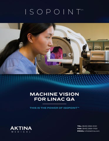

MACHINE VISION FOR LINAC QA


THIS IS THE POWER OF ISOPOINT™
THE POWER OF THE PHYSICAL ISOCENTER REFERENCE FRAME
The physical isocenter provides a stable first-principle reference point for isocenter root-cause analysis, optimization, and validation.

ULTRA-PRECISE OPTICAL TRACKING
A simple elegant solution for establishing physical isocenter as the idealized location for isocenter. This is a true breakthrough for LINAC QA.
DETERMINISTIC MARKER POSITIONING

INTUITIVE SOFTWARE
isoPoint™ allows you to position the marker with extreme precision and accuracy at the stable physical isocenter location. This powerful approach removes all the guesswork from isocenter optimization and characterization.
Workflows include physical isocenter determination, LINAC mechanical system checks, beam alignment, couch alignment, and

THE ISOPOINT™ FRAMEWORK
The isoPoint framework consists of modular and efficient steps for optimizing and characterizing isocenter.
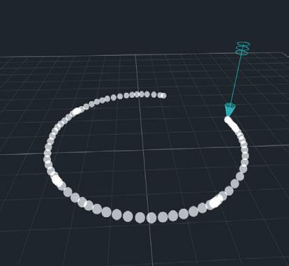
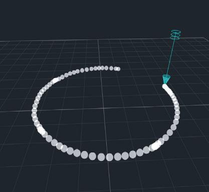
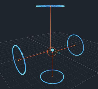
MEASURE THE COLLIMATOR AXIS
The collimator axes are measured with ultra-high precision optical tracking.


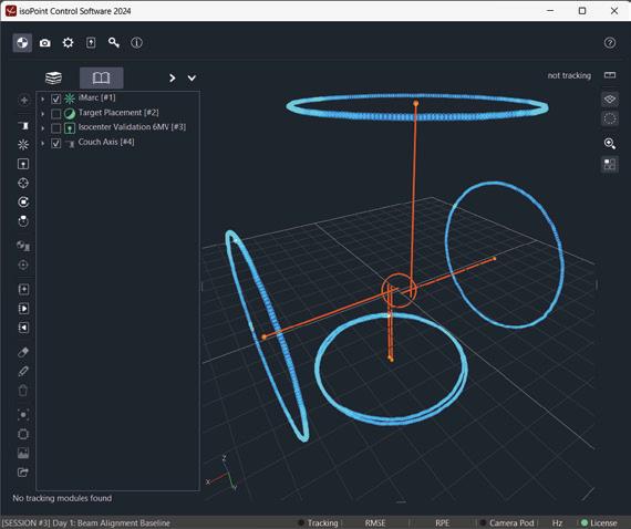
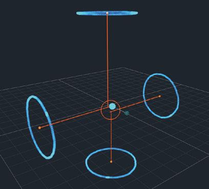
MEASURE THE IMARC DATASET
The iMarc dataset contains multiple different collimator axes measured at different gantry angles. Physical isocenter is computed from these axes.

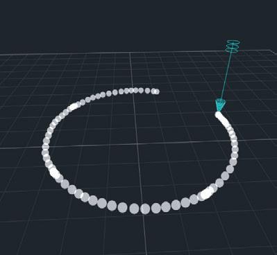


MEASURE THE COUCH AXIS OPTICALLY
Optical tracking is also used to measure the couch axis relative to physical isocenter.
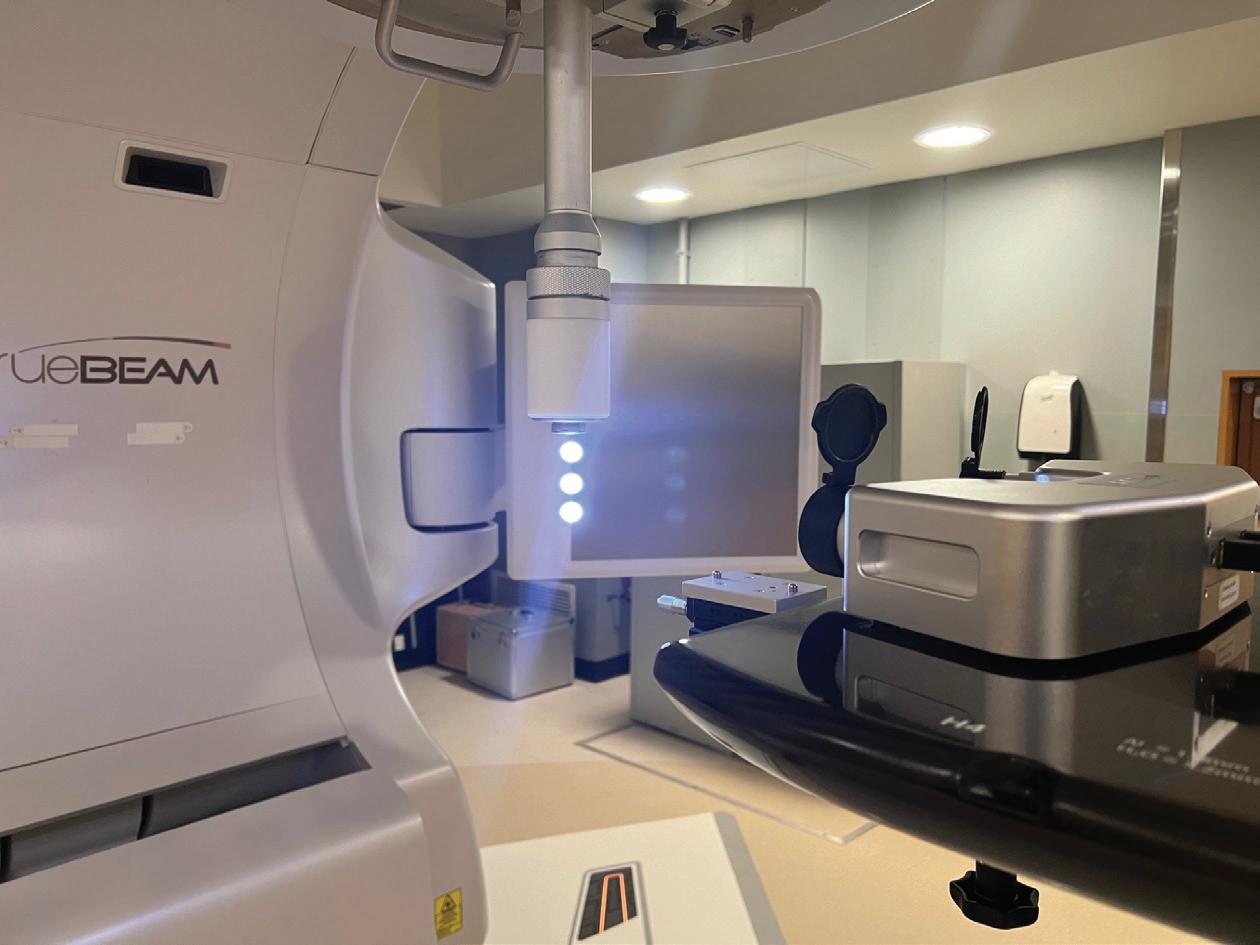
POSITION THE MARKER
The physical isocenter reference can be realized by using high-precision optical tracking to position a marker at physical isocenter.


MEASURE THE Z-MATRIX
The Z-matrix, a more comprehensive representation of treatment delivery, replaces the scalar radius of the radiation isocenter as a LINAC validation metric.


TEL: (845) 268-0101 | FAX: (845) 268-1700 | EMAIL: info@aktina.com
ISOPOINT™ HARDWARE
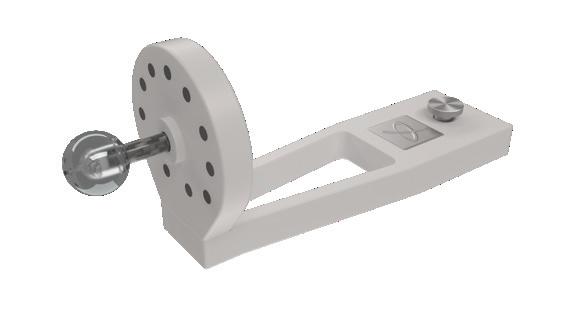
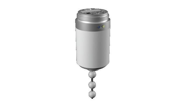
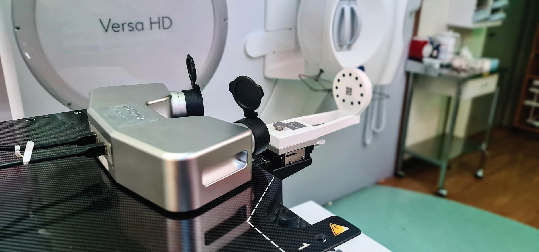
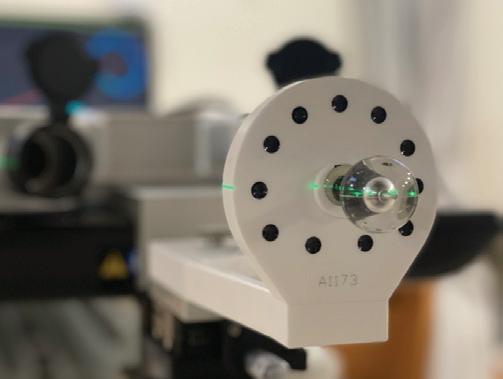
TARGET TRACKING MODULE
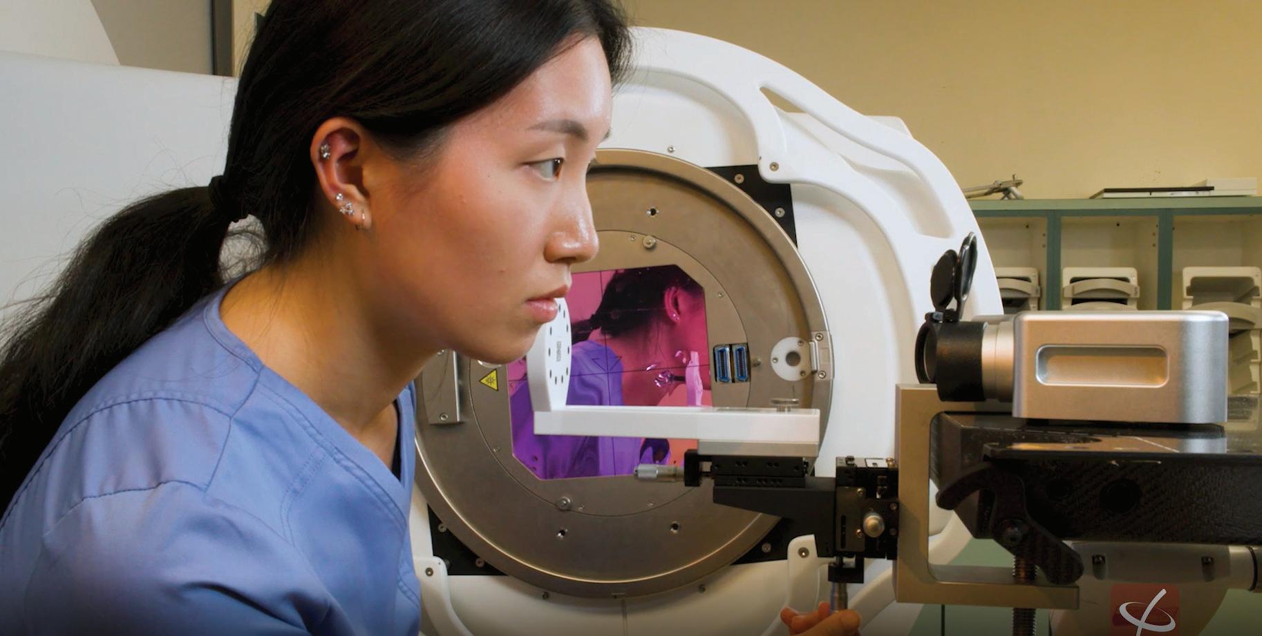
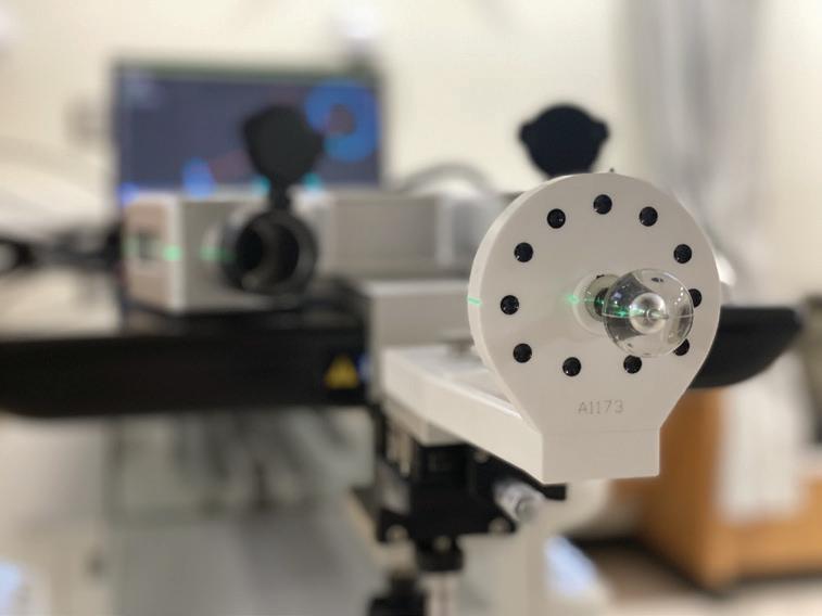
The target tracking module allows for high-precision positioning of a radiopaque spherical marker using optical tracking guidance. An 8 mm tungsten sphere is embedded within an acrylic sphere. The acrylic sphere allows for end-to-end accuracy checks as well as ensures uniform signal intensity around the radiopaque marker during transmission imaging. The thumb knob is used to secure the target module down to the target holder.
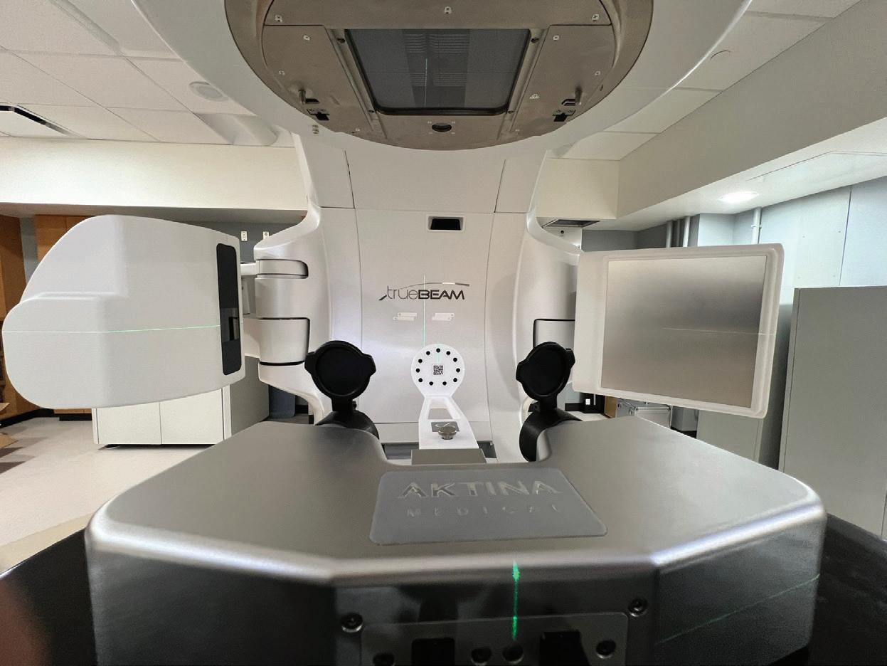
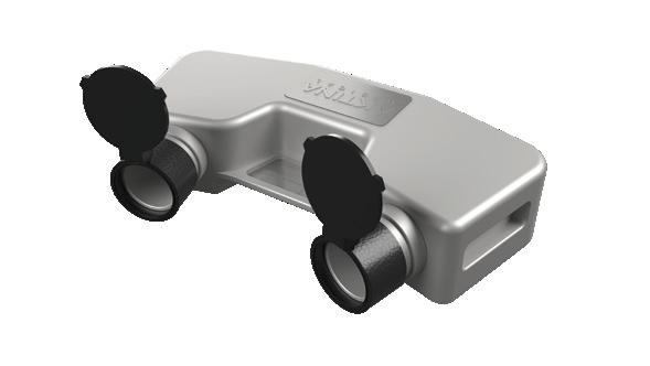
CAMERA POD
The isoPoint camera pod contains precision stereo vision cameras. There are two caps that protect the cameras. The handles on either side of the camera pod allow for easy handling. The alignment crosshairs are used to position the camera pod on the couch relative to the target holder.
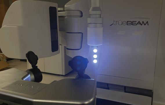
POINTER TRACKING MODULE
The pointer tracking module is used to measure axes of rotation (collimator and couch). It has three illuminated spheres that emit visible light. These spheres are used for performing high-precision optical tracking. The Pointer module communicates with the isoPoint™ software via a Bluetooth connection. Indicator LEDs provide information about Bluetooth connectivity and battery charge level.
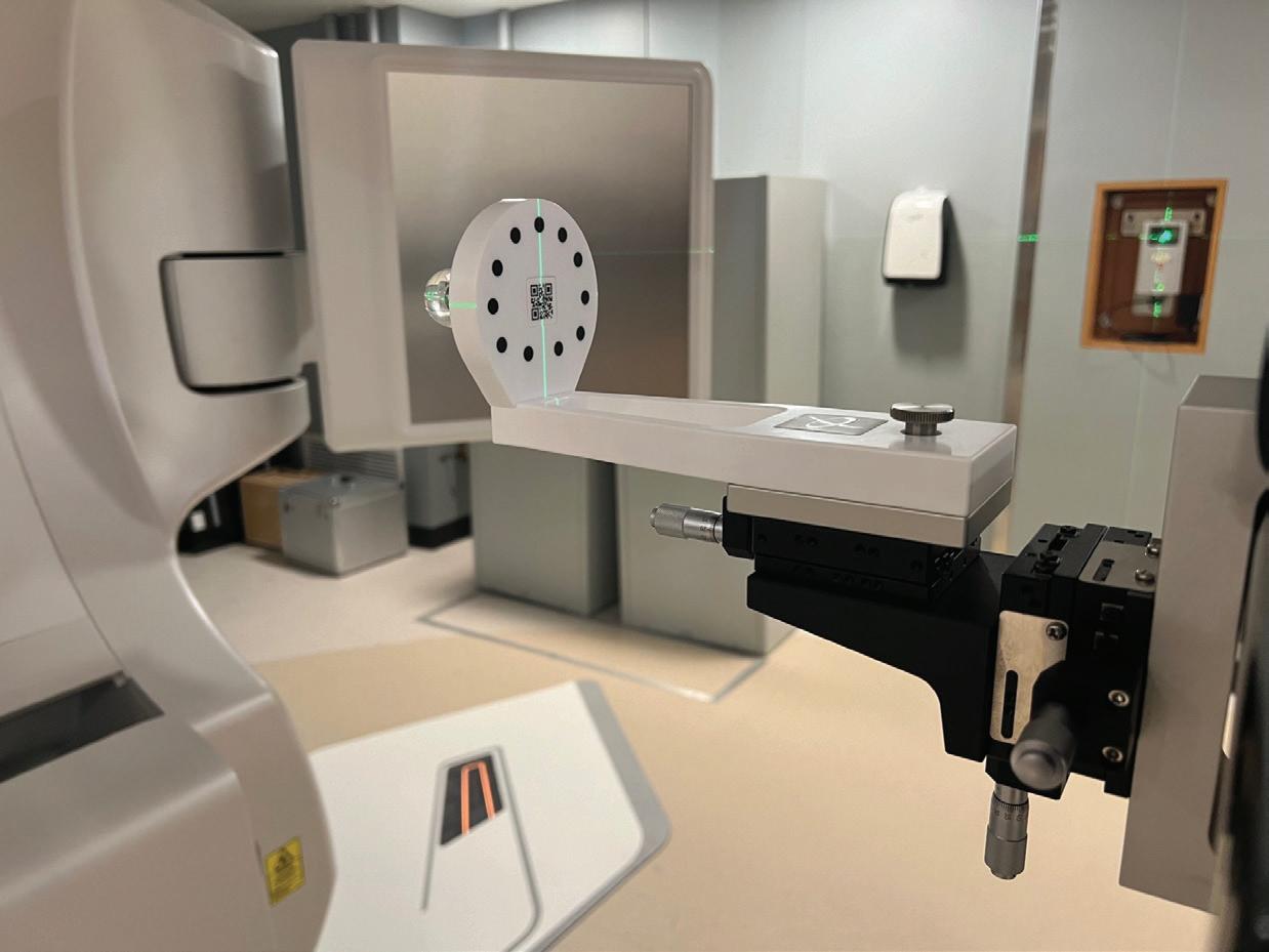
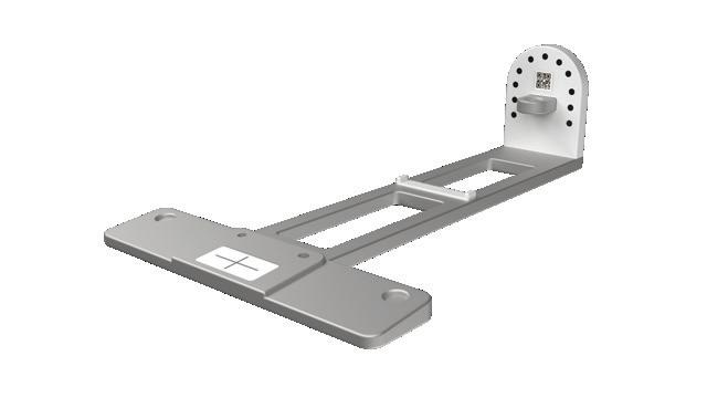
ACCURACY CHECK MODULE
The accuracy check assembly is used to perform quick system accuracy checks on your isoPoint™. The target should be placed in this assembly, and the isoPoint™ software automatically performs a full system accuracy check by comparing the expected and measured position of the acrylic sphere to ensure the mechanical integrity of the target assembly as well as accurate camera pod calibration.
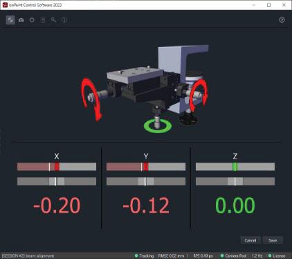
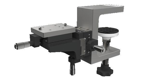
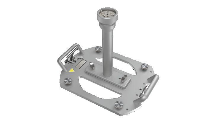
TARGET HOLDER
The target holder clamps to the end of the couch top and is used to position the target at the physical isocenter. The position of the target can be adjusted with three micro-positioning dials. The isoPoint™ software can be used to guide the target in real-time using optical guidance.
COLLIMATOR MOUNT
Two types of collimator mounting plates are available, depending on your LINAC: Varian or Elekta. These mounting plates securely affix the pointer tracking module to the LINAC collimator, enabling optical tracking measurements.

ISOPOINT™ TECHNOLOGY ADVANTAGE
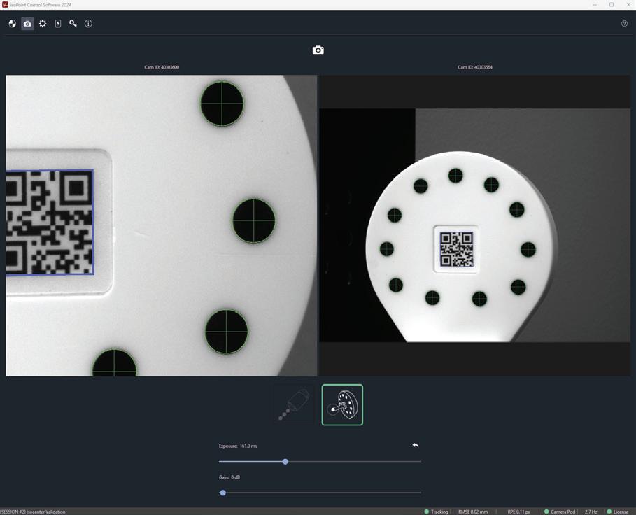
ULTRA-HIGH PRECISION MACHINE VISION
The isoPoint™ system uses advanced optical tracking technology to measure the mechanical movements of the LINAC as well as to position a tungsten sphere accurately within a reference frame defined by the optically measured collimator axes of rotation.
The isoPoint™ camera pod is the centerpiece of the isoPoint™ system's accuracy. It undergoes lengthy and extensive calibration at the Aktina factory, and a calibration and accuracy certificate is provided with your system.
The data within this certificate, when compared to in-field accuracy checks that can be performed in less than one minute, can be used as a baseline to ensure consistent accuracy of your system throughout its lifetime. With a precision of 0.01 mm and a marker placement accuracy of 0.1mm, isoPoint™ is changing how the physics community thinks about isocenter optimization and characterization.
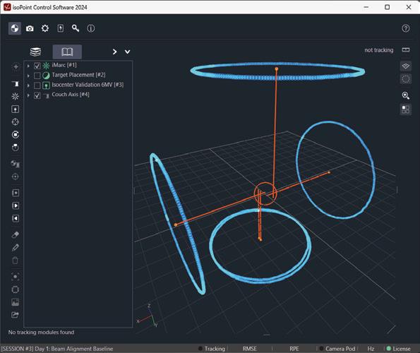
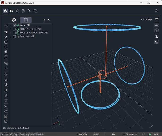
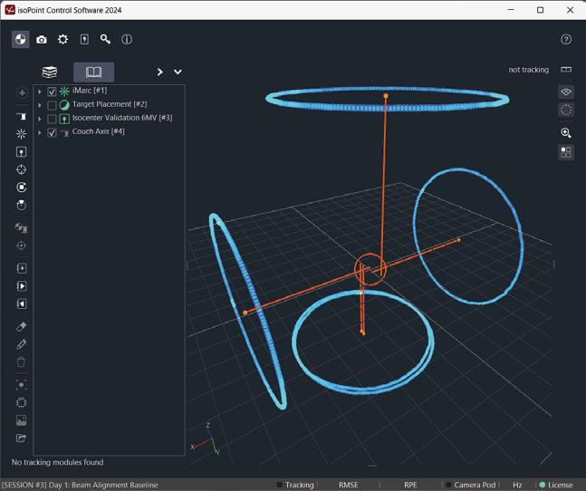
ISOPOINT™ SOFTWARE
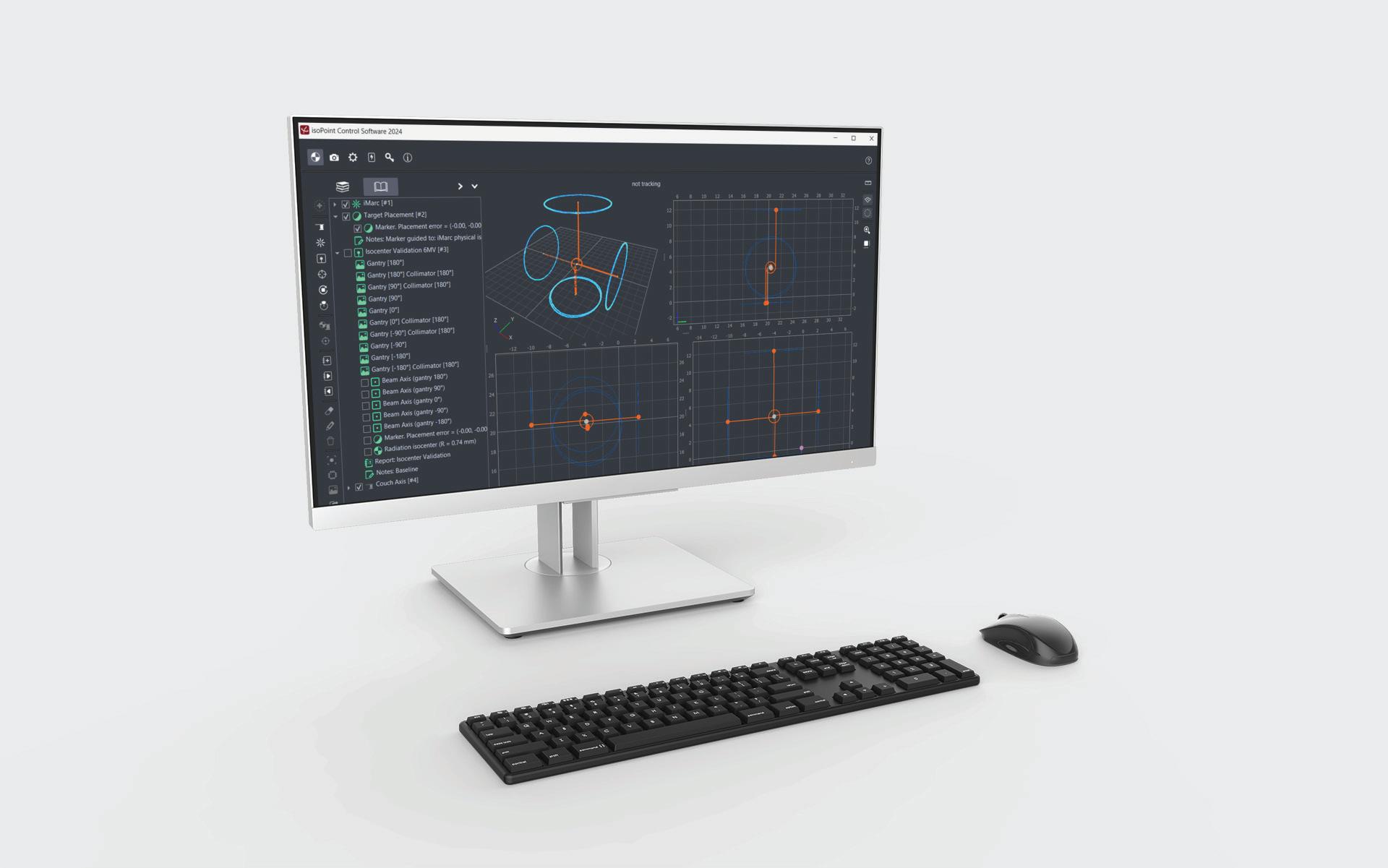
The isoPoint™ software streamlines all isocenter optimization and validation workflows. Developed, implemented, and rigorously tested by medical physicists dedicated to delivering an exceptional user experience.
Collaborate seamlessly with your team, utilize templates to enhance efficiency, navigate data with hierarchical tree views, export raw data for customized post-processing, and analyze LINAC performance data in both 2D and 3D views with previously unimaginable accuracy and precision.
OUR PATENTS
11617902: Modulated radiation beam alignment for medical linear accelerator (Granted)
11654301: System, process and apparatus to determine LINAC isocenter (Granted)
11298566: System, process and apparatus to determine LINAC isocenter (Granted)
▪ 11850450: Radiation beam alignment for medical linear accelerators (Granted)
▪ 8353112: Signal emitting or receiving pointer (Granted)
▪ 20220331608: X-ray transmission image analysis for the evaluation of LINAC isocenter quality (Pending)
TEL: (845) 268-0101 | FAX: (845) 268-1700 | EMAIL: info@aktina.com
TECHNICAL SPECIFICATIONS
1 OPTICAL TRACKING
ATTRIBUTE
Precision
Accuracy
Camera pod calibration
Rigid body registration (pointer)
Rigid body registration (target)
Tracking frequency (pointer)
Tracking frequency (target)
Marker placement accuracy
0.005 mm
0.01 mm over 10 mm (0.1%)
< 0.15 pixels reprojection error
< 0.25 mm RMSE
< 0.05 mm RMSE
9-11 Hz
4-6 Hz
< 0.1 mm
2 RADIATION TRANSMISSION IMAGE PROCESSING
ATTRIBUTE
Image compatibility
Marker and field detection accuracy TIFF / DICOM
< 0.05 mm
3 TARGET PHYSICAL PROPERTIES
ATTRIBUTE
Size
Material
Phantom
Stem
Translation stage type
Range
Translation stage precision
Translation accuracy
4 PHYSICAL PROPERTIES
8 mm diameter
Tungsten
1” acrylic sphere
Carbon fiber tube with 1 mm wall thickness
XYZ
100 mm
0.01 mm
0.05 mm over 100 mm (0.05 %)
VALUE
VALUE
VALUE
ATTRIBUTE VALUE
Case Dimensions Travel Case Weight 62 x 50 x 37 cm 22 kgs (48 lbs)
Travel
TECHNICAL SPECIFICATIONS
5 COMPUTER REQUIREMENTS
TEL: (845) 268-0101 | FAX: (845) 268-1700 | EMAIL: info@aktina.com
ATTRIBUTE VALUE Operating System Processor Memory (RAM) Storage Graphics Ports Wireless Connectivity Windows 11 Intel Core i5 or AMD Ryzen 5 (or higher) 8 GB DDR4 (or more) 256 GB SSD Integrated Intel UHD Graphics (or equivalent) USB 3.0 (at least two) Wi-Fi, Bluetooth
REGULATORY ATTRIBUTE VALUE Overvoltage (as per IEC 60601-1) Pollution (as per IEC 60601-1) Category 1 Category 1 7 ELECTRICAL ATTRIBUTE VALUE Pointer Tracking Module Power Li-Ion rechargeable (RRC1120), 2 amp-hours (approx. 2 days of heavy use) 5 VDC (Universal Serial Bus 3.0)
SOFTWARE LICENSING ATTRIBUTE VALUE Type Levels Annual subscription model Core, Imaging, Tracking, Isocenter Validation Camera Pod
6
8


TEL: (845) 268-0101 | FAX: (845) 268-1700 | EMAIL: info@aktina.com © 2024 AKTINA MEDICAL | VER. 80800BR1 | REV. 6.20.24