Hybrid Energy Management and Control Strategy of Photovoltaic Generation Systems
Brajesh Kumar Ravi1, Prof. Rakesh Rohan21Research Scholar, 2Assistant Professor, 1&2Department of Electrical Engineering 1&2Birsa Institute of Technology Sindri, India
Abstract: Energy storage is the capture of energy produced for use at a time to time. Hybrid storage devices are used in microgrids to provide power backup solutions when the distributed energy resources (DERs) are unable to supply the load demands. This work deals with the design and stability analysis of a DC microgrid with batterysupercapacitor energy storage system under variable supercapacitor operating voltage. The conventional design method reported in the literature considers the rated supercapacitor voltage in the modeling and design of controllers. However, the supercapacitor unit can discharge aslow as 10% of its rated voltage due to self discharge. It is observed that the conventional method of controller design can potentially make the system unstable. This paper proposed an optimal super capacitor voltage to be considered in the design is calculated and a design method is proposed to ensure the stability of DC microgrid in all operating modes.
Keywords: Energy management, MPPT, bidirectional power converter,photovoltaic, supercapcitor,battery, hybrid power unit.
I. INTRODUCTION
The permeability of renewable energy in the microgrid is relatively high, and its intermittence will lead to the fluctuation of power supply in the system. At the same time, the sudden change of load and switch will cause voltage flicker and drop of DC bus, which will threaten the stable operation of the system. The DC microgrid composed of photovoltaic power generation, battery energy storage device, grid converter and DC and it is used as the research object load in this work, what's more, based on the bus voltage information, the operation control strategy of microgrid is designed to realize the independent operation of the microgrid, such as parallel in and off the grid. Tremendous advancements occurred over the next century: the development of induction and synchronous machines, electric meters, high voltage transmission, gas turbines, nuclear reactors, wind turbines, and solar photovoltaic’s, to name a few. All of these technologies were turned to the development, advancement, and expansion of "the grid;" the system of large-scale centralized generation connected to energy users through a network of transmission and distribution. But while a seemingly endless supply of effort and funding was being poured into "the largest machine ever built", in recent years another trend in research started, as some began to explore the advantages to moving in the other direction: distributed, decentralized, local grids: microgrids. Batteries and supercapacitors use dc current by their na- ture for charging and discharging. This includes the batteries in electrical vehicles, meaning dc power systems can easily integrate with vehicle-to-grid systems. In addition to the benefits of increasing electrification, another key area of research seeks to identify the most cost effective means for improving electricity access. Several studies have compared outcomes for grid extension vs decentralized generation (using an average cost for all feasible sources), grid extension vs solar home systems (SHS) , SHS vs solar photovoltaic (PV) microgrids, and a three-way comparison between grid extension, renewable-based home systems, and renewable-based microgrids . Each of these studies analyzes some combination of transmission, distribution, fuel, and capital costs for the RE options considered. In general, the results of these studies indicate that while grid extension is typically the least-cost option for RE, decentralized options are significantly more cost-effective in remote and/or sparsely populated areas. In particular, found that in several Sub-Saharan African nations, over 50% of the population could best be served with offgrid power systems. In addition, the rapid decline of solar PV pricing over the last few years indicates that the extent of territory where SHS and PV microgrid systems are the best option will likely increase instead of decrease.
Figure 1: Schematic diagram of a DC micro grid system
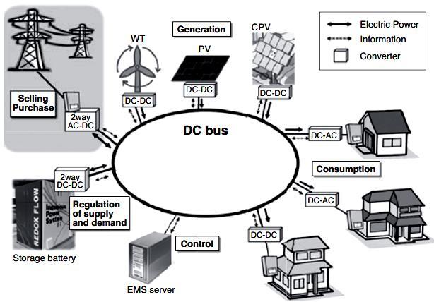
Many types of electrical loads use dc power natively
The majority of electronics (such as computers, servers, and TVs) use dc power. LED lights also use dc power natively. Many types of motors and drives (especially variable speed drives) use dc power. In all three cases, these sources, storage systems, and loads require converters when- ever they interface with ac power systems; thus switching to a dc power system eliminates the need for such converters, eliminating the losses which are inherent in any type of power conversion. To date, key areas of implementation for dc power systems have included data centers, spacecraft, airplanes, shipboard power systems, traction power systems (for trains, trolleys, trams, etc), and telecommunication infrastructure. Developments in these areas have spurred research on dc microgrids, and in some cases provided test-beds for establishing functional dc microgrids (particularly in the case of data centers and telecoms, where the cost savings potential is significant).
II. LITERATURE SURVEY
J. Hong et al.,[1] into thought. The reenactments are directed utilizing the Matlab/Simulink programming to check the activity execution of the proposed PV/battery hybrid conveyed power age framework with the comparing control calculations, where the MPPT control circle, the battery charging/releasing administration circle are empowered in like manner in various working situations.
I. Ameur et al.,[2] propose an ideal power the board for an independent microgrid made out of a Photovoltaic cluster (PV), a Fuel-Cell framework (FC) and an electrochemical battery dependent on the Pontryagin's Most extreme Guideline (PMP). The three sources are interfaced in corresponding to a typical DC-connect by means of DC/DC converters and are intended to fulfill the heap need particularly in regions outside the power inclusion. The goal of the proposed procedure is to lessen the fuel utilization by causing the framework to work in its ideal working point as for load request and climate conditions. Some reproduction results are introduced to affirm the optimality of the proposed system.
L. Liu et al.,[3] presents the quick and precise administration of different smaller scale power sources in the framework can be acknowledged and the steady activity and high-effectiveness control of the power age framework likewise can be guaranteed. At long last, the outcomes completely show that this examination can assist with controlling the activity of disseminated power gracefully and energy stockpiling unit, and add to building multi-energy reciprocal microgrid in provincial and distant zones and off-matrix power flexibly [3].
K. Longo et al.,[4] The presents model is executed in MATLAB/Simulink condition. Two situations are mimicked to cover the fundamental control objective, for example the balance between power creation and burden request through DC transport. The subsequent situation additionally attempts to amplify the power creation. Another accomplishment of this work is the conversation about the Hybrid Energy Stockpiling Framework (HESS), utilizing supercapacitor to maintain a strategic distance from weight on the battery. The microgrid is estimated and reproduced for a family of ten houses, fixing energy and power utilization for the city Porto Cesareo. This work covers the entire recreation procedure of a microgrid and could be a fascinating base to develope progressively complex DC microgrid structures later on.
J. Kang et al.,[5] The proposed control and power the board framework steadily manage the transport voltage and well equalization the power, basically through programmed control of every module's voltage and power. Under the influence and Power the board framework, when the heap changes abruptly, the transport voltage stay stable and power stay adjusted. The reproduction is completed to confirm the exhibition of the proposed strategy.
International Journal of Electrical and Electronics Research ISSN 2348-6988 (online)
Vol. 9, Issue 3, pp: (13-22), Month: July - September 2021, Available at: www.researchpublish.com
Y. Singh et al.,[6] High request versatile channel based synchronization controller is executed for smooth changing to independent mode and the other way around with high dependability and hang less control. A MOSSI based control accomplishes matrix current, PCC (Purpose of Regular Coupling) voltage, and battery current under characterized modes and aides in music relief and upgrading the power nature of the single stage framework however removing power from the sunlight based PV cluster. The viability of the proposed structure of MOSSI-PLL is assessed through test results under various modes and conditions on the created model in the research center.
H. Mahmood et al.,[7] The decentralized coordination conspire organizes accusing the microgrid batteries of lower SOC. Likewise, the control procedure empowers the hybrid units to import power from different units to help charging their batteries. These highlights are accomplished by utilizing the proposed multi-portion versatile power/recurrence qualities in the hybrid unit controllers. Since the technique depends entirely on the nearby voltage controllers, neither a focal energy the board framework nor interchanges among various units are required. The created technique has been approved utilizing nitty gritty exchanging models in PSCAD/EMTDC.
S. Umashankar et al.,[8] This work centers around the remuneration of PV power decrease because of fractional concealing utilizing bidirectional half extension converter with battery stockpiling. This framework considers satisfying the nearby burden request through PV creation and, at that point, to deal with the power among the battery and matrix. In the proposed framework, the considered power molding gadgets territory support converter, 3 stage full-connect inverter, and bi-directional converter. The outcomes are acquired from the MATLAB/SIMULINK condition.
Dongxu Wang et al.,[9] This work presents the displaying and reproduction of the utilization of virtual coordinated generator(VSG) innovation in a bidirectional DC/Air conditioning converter and a PV/battery framework in a hybrid air conditioning/DC microgrid. The battery unit in the DC sub-microgrid keeps up DC transport voltage stable and the DC transport is proportional to a capacity framework. The voltage-controlled kind of VSG control system is applied to the bidirectional DC/Air conditioning converter being as the help hub in hybrid air conditioning/DC microgrid.
Yanping Zhu et al.,[10] Dependent on microgrid recurrence, another photovoltaic (PV)/battery (BA)/fuel cell (FC) hybrid energy the board procedure with changed hang control for islanded application is proposed in this paper. This procedure empowers the attachment and plays ability in the disseminated units with voltage control mode and makes it conceivable to abstain from utilizing the correspondence line or a focal director. The framework recurrence filling in as the specialist furnishes the units with the chances to adaptively look after age/load balance as indicated by various circumstances with just nearby data.
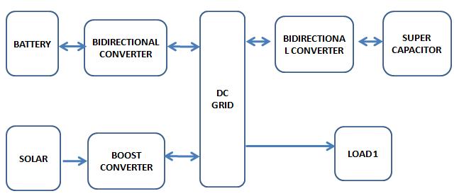
Proposed model
Figure 2: Model Flow Chart
The flow chart of proposed model is based on the control strategy for the DC microgrid considered in this work. There are four possible operating modes. The control strategy regulates the DC link voltage in all the four operating modes using battery or PV source. The four operating modes are explained below.
1) Battery Discharging Mode (BDM): In this mode, the PV power is less than the load power and the battery SoC is within limits. Therefore, the battery discharges to regulate the DC link voltage.
2) Load Shedding Mode (LSM): In this mode, the PV power is less than the load power and the battery is fully discharged. Therefore the loads are disconnected and the available power is used to charge the battery.
International Journal of Electrical and Electronics Research ISSN 2348-6988 (online) Vol. 9, Issue 3, pp: (13-22), Month: July - September 2021, Available at: www.researchpublish.com
3) Battery Charging Mode (BCM): In this mode, the PV power is more than the load power and the battery SoCis within limits. Therefore, the battery regulates the DC link voltage by charging with the excess power available.
4) PV Off-MPPT Mode (POM): In this mode, the battery has fully charged, therefore, the PV is operated in off-MPPT mode to regulate the DC bus voltage.
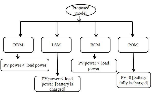
Figure 3: Operation flow chart
The figure 3 is showing the operational flow chart which is discussed above.
Figure 4: Proposed model
Figure 4 is showing proposed HESS DC-microgrid model. This model consist various sub models which is described in details.
Sub-Modules
• Solar power
• MPPT Algorithm
• PWM Switching
• Boost converter
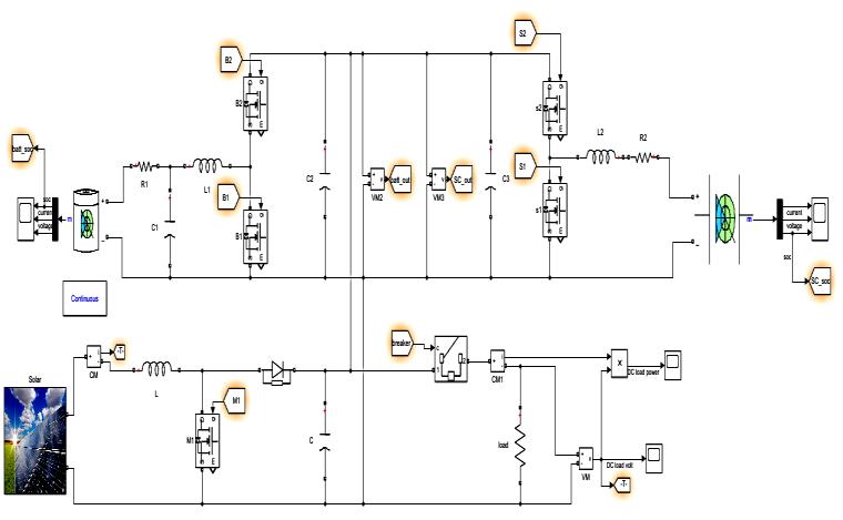
• Bidirectional converter and mode of operation
• Battery
• Super capacitor
International Journal of Electrical and Electronics Research ISSN 2348-6988 (online) Vol. 9, Issue 3, pp: (13-22), Month: July - September 2021, Available at: www.researchpublish.com
III. SIMULATION RESULTS
A. Steady State Simulation Results
Scenario 1:
Battery Discharging Mode (BDM): In this mode, the PV power is less than the load power and the battery SoC is within limits. Therefore, the battery discharges to regulate the DC link voltage.
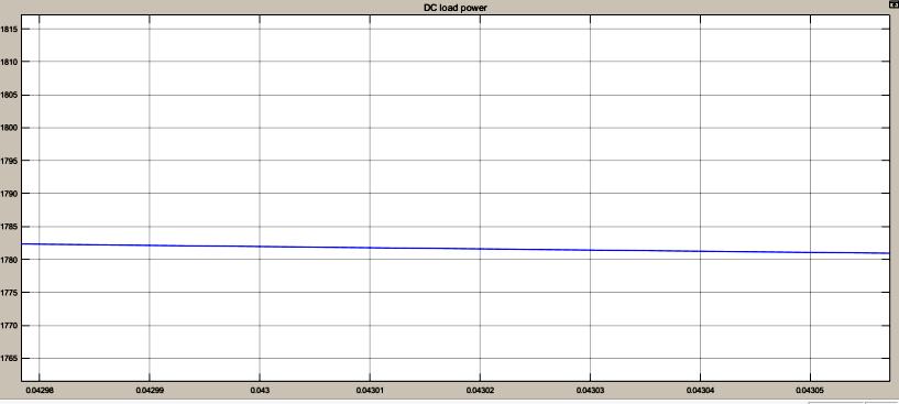
Figure 5: DC Load Power
Figure 5 is showing DC load power graph. Here X axis is denoting as a time scale and Y axis is denoting as a value of power. So load power value is 1782W.
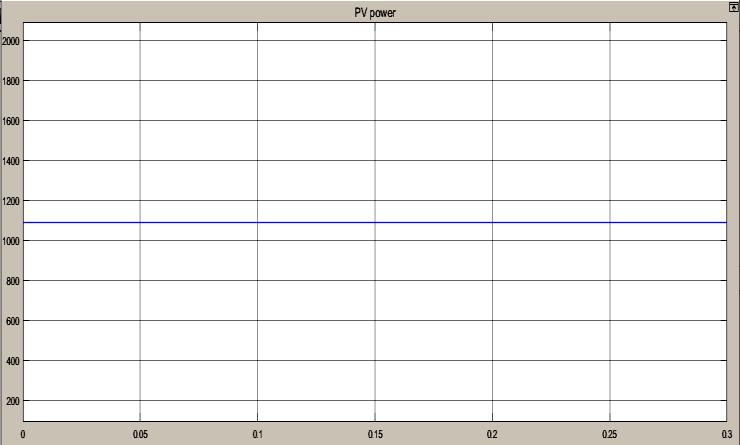
Figure 6: Solar (PV) Power
Figure 6 is showing Solar power graph. Here X axis is denoting as a time scale and Y axis is denoting as a value of PV power. So Solar (PV) power value is 1100W. PV characteristic curves with Irradiance =1 kW/m2 (Temperature C= 25). Here, the solar power is 1100watts < load power is 1782watts.
Figure 7: DC Load Voltage
Figure 7 is showing DC load voltage graph. Here X axis is denoting as a time scale and Y axis is denoting as a value of voltage. Therefore value of DC load voltage is 425V.

International Journal of Electrical and Electronics Research ISSN 2348-6988 (online) Vol. 9, Issue 3, pp: (13-22), Month: July - September 2021, Available at: www.researchpublish.com
Figure 8: Battery (SOC, Current, Voltage)
Figure 8 is battery state of charge,voltage and current graph. Here X axis is denoting as a time scale and Y axis is denoting as a state of charge, value of current and voltage.
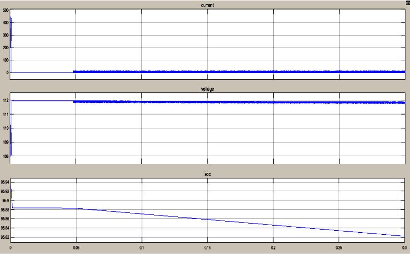
Here, the battery discharge to compensate the load power
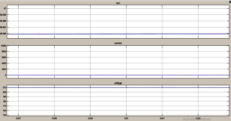
Figure 9: Super Capacitor (Current, Voltage, SOC)
Figure 9 is super capacitor state of charge, voltage and current graph. Here X axis is denoting as a time scale and Y axis is denoting as a value of current, voltage and state of charge. Here, the super capacitor is discharge to compensate the load power.
Table 1: Simulation parameters
Sr No. Parameter Value 1 DC Load Power 1782watts 2 Solar (PV) Power 1100watts 3 Battery SOC 97
Battery Current 5A
Battery Voltage 210V 6 Super Capacitor SOC 95 7 Super Capacitor Current Aprox 0 8 Super Capacitor Voltage 112V 9 DC Load Voltage 500V 10 Solar(PV) Voltage 450V
Scenario 2
Load Shedding Mode (LSM): In this mode, the PV power is less than the load power and the battery is fully discharged. Therefore the loads are disconnected and the available power is used to charge the battery.
International Journal of Electrical and Electronics Research ISSN 2348-6988 (online) Vol. 9, Issue 3, pp: (13-22), Month: July - September 2021, Available at: www.researchpublish.com
Figure 10: DC Load Power
Figure 10 is showing DC load power graph. Here X axis is denoting as a time scale and Y axis is denoting as a value of power. Here, the load is disconnected to charge the battery.
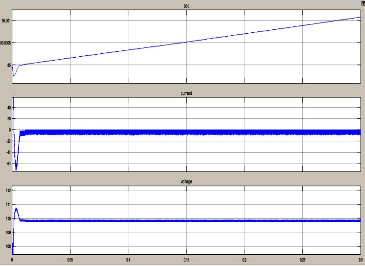
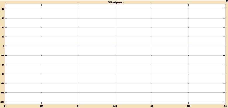
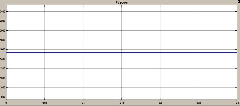
Figure 11: Solar (PV) Power
Figure 11 is showing Solar (PV) power graph. Here X axis is denoting as a time scale and Y axis is denoting as a power. Therefore value of power is 1538W.
Scenario 3
Battery Charging Mode (BCM): In this mode, the PV power is more than the load power and the battery SoC is within limits. Therefore, the battery regulates the DC link voltage by charging with the excess power available.
Figure 12: Battery (SOC, Current, Voltage)
Figure 12 is battery state of charge,voltage and current graph. Here X axis is denoting as a time scale and Y axis is denoting as a state of charge, value of current and voltage. Here, the battery is charging.
SCENARIO 4
PV Off-MPPT Mode (POM): In this mode, the battery has fully charged, therefore, the PV is operated in off-MPPT mode to regulate the DC bus voltage.
International Journal of Electrical and Electronics Research ISSN 2348-6988 (online) Vol. 9, Issue 3, pp: (13-22), Month: July - September 2021, Available at: www.researchpublish.com
Figure 13: MPPT Output
Figure 13 is showing MPPT output. Here X axis is denoting as a time scale and Y axis is denoting as a MPPT output voltage. Therefore when MPPT is in OFF state then value of voltage is 0V.
B. Dynamic Response Simulation Results
The dynamic performance of the system with the irradiance dropping from 1000 W/m2 to 500 W/m2 at t = 1 to 10 sec, the simulation results is presented in various operating modes. Other simulation conditions are as follows: Temperature = 25C and load power. The DC bus voltage Vbus keeps stable during the transition. In this scenario the MPPT loop always takes charge of the control of the duty cycle D. There is a slight rise of the PV reference voltage Vref, due to the variation of the PV characteristic curve during the transition.
Table 2: Simulation parameters
Sr No. Parameter Value
1 DC Load Power 1170 watts
2 Solar (PV) Power 1000 watts
3 DC Load Voltage 500V
4 Solar(PV) Voltage 450V
Battery Discharging Mode (BDM): In this mode, the PV power is less than the load power and the battery SoC is within limits. Therefore, the battery discharges to regulate the DC link voltage.
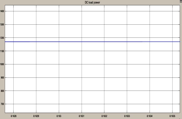
Figure 14: DC Load Power
Figure 14 is showing DC load power graph. Here X axis is denoting as a time scale and Y axis is denoting as a value of power. So load power value is 1170W.
International Journal of Electrical and Electronics Research ISSN 2348-6988 (online) Vol. 9, Issue 3, pp: (13-22), Month: July - September 2021, Available at: www.researchpublish.com
Figure 15: Solar (PV) Power
Figure 15 is showing Solar power graph. Here X axis is denoting as a time scale and Y axis is denoting as a value of PV power. So Solar (PV) power value is 1100W. PV characteristic curves with Irradiance =500 W/m2 (Temperature C= 25). Here, the solar power is 1000watts < load power is 1170watts.
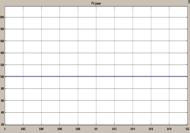
Table 3: Comparison chart of proposed work with Base Work
Sr No. Parameters Previous Work Proposed Work
1 PV Max Power 9.6KW 11KW 2 MPPT Voltage 435V 450V 3 Nominal DC Voltage 500V 500V 4 Battery Nominal voltage 200V 200V 5 Battery max charged voltage 208V 210V 6 State of Charge NA 97% 7 Super capacitor NA Yes 8 Mode of operation 7 4 9 Sub-Module PV, MPPT, Bi-directional converter, PV, MPPT, Bi-directional converter,
10 Controller Conventional incremental conductance MPPT technique and PI Controller Energy Control Controller
Therefore proposed model simulation result for performance is better than previous model in terms battery, load, and super capacitor. Proposed model gives significant improved results.
IV. CONCLUSION
The simulation contemplates performed with the SC and battery bank models and their charge controllers show that the battery bank is undeniably increasingly appropriate to give power over a long timeframe. The exponential idea of its voltage discharge bend has a considerable region of stable voltage output and can be effectively used to give base power to DC loads. In any case, at whatever point there is an unexpected high prerequisite of power, the battery can't adapt to it. The huge homeless people in the system can be dealt with by a SC bank which discharges high power over brief timeframe periods. Simulated results show that the proposed models give better results than previous.
REFERENCES
[1] J. Hong, J. Yin, Y. Liu, J. Peng and H. Jiang, "Energy Management and Control Strategy of Photovoltaic/Battery Hybrid Distributed Power Generation Systems With an Integrated Three-Port Power Converter," in IEEE Access, vol. 7, pp. 82838-82847, 2019, doi: 10.1109/ACCESS.2019.2923458.
[2] I. Ameur and A. Benalia, "PMP Based Optimal Power Management of a PV-Fuel-Cell-Battery Hybrid Power Source," 2019 International Conference on Advanced Electrical Engineering (ICAEE), Algiers, Algeria, 2019, pp. 16, doi: 10.1109/ICAEE47123.2019.9015184.
International Journal of Electrical and Electronics Research ISSN 2348-6988 (online) Vol. 9, Issue 3, pp: (13-22), Month: July - September 2021, Available at: www.researchpublish.com
[3] L. Liu, H. Feng, J. Zhang, Q. Zeng, Q. Hu and J. Wu, "Design and Operation Control of “Photovoltaic-BatterySOFC” Hybrid Power Generation System," 2019 Chinese Automation Congress (CAC), Hangzhou, China, 2019, pp. 4968-4975, doi: 10.1109/CAC48633.2019.8997361.
[4] K. Longo and S. Vergura, "Model and control of a combined PV-storage system into a microgrid," 2019 IEEE International Conference on Environment and Electrical Engineering and 2019 IEEE Industrial and Commercial Power Systems Europe (EEEIC / I&CPS Europe), Genova, Italy, 2019, pp. 1-6, doi: 10.1109/EEEIC.2019.8783347.
[5] J. Kang, H. Fang and L. Yun, "A Control and Power Management Scheme for Photovoltaic/Fuel Cell/Hybrid Energy Storage DC Microgrid," 2019 14th IEEE Conference on Industrial Electronics and Applications (ICIEA), Xi'an, China, 2019, pp. 1937-1941, doi: 10.1109/ICIEA.2019.8833994.
[6] Y. Singh, B. Singh and S. Mishra, "Multi-Objective Control Algorithm for Solar PV-Battery based Microgrid," 2018 2nd IEEE International Conference on Power Electronics, Intelligent Control and Energy Systems (ICPEICES), Delhi, India, 2018, pp. 611-616, doi: 10.1109/ICPEICES.2018.8897322.
[7] H. Mahmood and J. Jiang, "Autonomous Coordination of Multiple PV/Battery Hybrid Units in Islanded Microgrids," in IEEE Transactions on Smart Grid, vol. 9, no. 6, pp. 6359-6368, Nov. 2018, doi: 10.1109/TSG. 2017.2709550.
[8] S. Umashankar, A. Mathur and M. Kolhe, "Control and power management of Photovoltaic-battery based micro grid," 2016 3rd International Conference on Electrical Energy Systems (ICEES), Chennai, 2016, pp. 128-132, doi: 10.1109/ICEES.2016.7510629.
[9] Dongxu Wang and Hongbin Wu, "Application of virtual synchronous generator technology in microgrid," 2016 IEEE 8th International Power Electronics and Motion Control Conference (IPEMC-ECCE Asia), Hefei, 2016, pp. 3142-3148, doi: 10.1109/IPEMC.2016.7512798.
[10] Yanping Zhu, Bingjie Liu and Xiaofeng Sun, "Frequency-based power management for PV/battery/ fuel cell standalone microgrid," 2015 IEEE 2nd International Future Energy Electronics Conference (IFEEC), Taipei, 2015, pp. 16, doi: 10.1109/IFEEC.2015.7361445.
[11] Y. Guan, J. C. Vasquez, J. M. Guerrero, Y. Wang and W. Feng, "Frequency Stability of Hierarchically Controlled Hybrid Photovoltaic-Battery-Hydropower Microgrids," in IEEE Transactions on Industry Applications, vol. 51, no. 6, pp. 4729-4742, Nov.-Dec. 2015, doi: 10.1109/TIA.2015.2458954.
[12] J. Khajesalehi, K. Sheshyekani, M. Hamzeh and E. Afjei, "High-performance hybrid photovoltaic -battery system based on quasi-Z-source inverter: application in microgrids," in IET Generation, Transmission & Distribution, vol. 9, no. 10, pp. 895-902, 2 7 2015, doi: 10.1049/iet-gtd.2014.0336.
[13] H. Mahmood, D. Michaelson and J. Jiang, "A Power Management Strategy for PV/Battery Hybrid Systems in Islanded Microgrids," in IEEE Journal of Emerging and Selected Topics in Power Electronics, vol. 2, no. 4, pp. 870882, Dec. 2014, doi: 10.1109/JESTPE.2014.2334051.
[14] Z. Wu, H. Tazvinga and X. Xia, "Optimal schedule of photovoltaic-battery hybrid system at demand side," 2014 13th International Conference on Control Automation Robotics & Vision (ICARCV), Singapore, 2014, pp. 553-558, doi: 10.1109/ICARCV.2014.7064364.
[15] H. Mahmood, D. Michaelson and J. Jiang, "A Power Management Strategy for PV/Battery Hybrid Systems in Islanded Microgrids," in IEEE Journal of Emerging and Selected Topics in Power Electronics, vol. 2, no. 4, pp. 870882, Dec. 2014, doi: 10.1109/JESTPE.2014.2334051.
