Prospects and challenges of Photovoltaic Solar Power System in the Global Energy Mix
AMIEYEOFORI VALENTINE FELIX SCHOOL OF SCIENCE AND ENGINEERING, ALTANTIC INTERNATIONAL UNIVERSITY HONOLULU, HAWAIAbstract: The current energy transition will no doubt position renewables strategically in the global energy mix from 2040, with Solar and Wind Energy playing dominant roles in the energy mix. However, the paper noted that though wind energy conversion is more efficient than solar energy, the availability, unpredictability and variability of wind is harder to forecast, than solar energy which can easily be predicted: is only available during the day except when there are clouds. Solar technology therefore can easily become a game changer for many developing countries as it can promote wide-spread energy security due its lower cost compared with fossil fuel in many countries. It can also provide universal access to electricity, with a shorter construction timeline, and has ability to provide firm power when combined with battery storage. The paper further noted that solar electricity generation can also potentially mitigate against climate change risk if used at global scale, which is driven by efficient Photovoltaic (PV) technology, which can also become the most significant electricity generation contributor among all other candidates of renewable energy by 2040. In spite of these prospects the paper recognized some challenges with PV technology in large scale electricity generation, such as the less than 25 percent efficiency in commercial photovoltaic cells, a measure that determines how much of the radiation can be converted and be usable. There is also the issue of Nitrogen trifluoride, a common byproduct of electronics manufacture, including those used in solar cells, that generates greenhouse gas of about 17,000 times more potent than carbon dioxide. Another major challenge, is in the full integration of solar power with existing electricity grid, as most of the electric distribution systems are designed, operated and protected on the assumption that there is a single source of voltage on each distribution feeder. Finally, the paper recommended that to deploy a sustainable, efficient, and cost-effective solar energy system that can play more significant roles in the global energy mix, would require consistent engineering and technological innovations, and that these technological advances must be backed up by policies that will encourage both government and private funding of R&D in innovative solar technologies, and to also establish Commercial frameworks that will facilitate trade and business transactions within the solar energy spectrum.
Keywords: Renewable Energy, Solar Energy, Photovoltaic Cells, Electricity generation, Grid System, Innovative technologies
1. INTRODUCTION
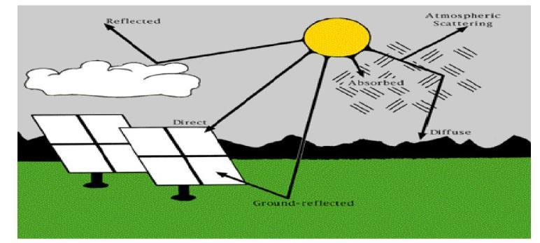
Solar Energy is the energy derived by directly harnessing the sun radiation that hits the earth surface (West, 1993), which according to Rajput (2017) comes in the form of ultra-violet, visible and infrared radiation, and depends greatly on geographic location, time of day, season, land scope and local weather. Also, since the earth is spherical, the sun rays strike the earth surface at different angles ranging from 0° to 90°, with the maximum radiation energy when the rays are vertical to the earth surface. Rajput (2017) further showed that the radiation from the sun takes different paths as shown in figure 1, with some rays reflected by the atmospheric clouds away from the earth surface, while another set of rays are absorbed, or scattered by atmospheric air molecule, water vapours, clouds, dust and pollutants, which eventually become diffused before reaching the earth surface. However, the most effective radiation is the one that hits the earth’s surface directly.
The sun provides the source of energy for the earth, which like other planets orbits around the sun, with most of the sun’s energy coming from photosynthesis, a process that enables plants to convert solar energy into chemical form by synthesizing glucose from sunlight, carbon dioxide, and water, with oxygen as waste product In terms of composition, the sun is made of about 74% by mass of hydrogen, 25% of helium, and the rest are trace quantities of heavier elements. (Kalogirou, 2014). The earth’s orbit around the sun in a slightly elliptical form, which alters the distance between the two throughout the year, with a distance of 91.4 million miles apart in January compared to 94.5millionmiles in July, with an annual disparity of 3%–4% in the irradiance at the edge of the atmosphere. (Almusaied et al 2018).
Structurally, the Sun contributes about 99.68% by mass of the total mass of the solar system (Jager et al 2014).
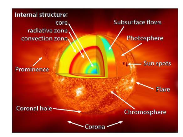
Figure 2 shows the sun as a sphere of intensely hot gaseous matter with approximate diameter of 1.39x 10⁹m. (Kalogirou, 2014), having an outer visible layer called the photosphere that has a temperature of about 6000°C. Above this is the transparent layer of gases known as chromospheres, which emits lights of short wave length, while the outer part of the sun is the corona, which has the Prominence, that consist of immense clouds of glowing gas that erupts from upper chromospheres. The corona can only be seen during total solar eclipse. (Rajput, 2017).
In relations to the earth surface, the sun is about 1.5 x10⁸ km away from earth, and because thermal radiation travels with the speed of light in vacuum (about 300,000 km/s), the sun solar energy reaches the earth in 8 min and 20 s. As shown in figure 3, the sun radiation hits the earth surface in the form of a disk with an angle of 32 min of a degree, which is very useful in such applications as concentrator optics. With an effective blackbody temperature of 5760 K or about 6000 C, and a higher temperature in the central region, the sun is a continuous fusion reactor that turns hydrogen into helium and produces total energy output of 3.8 x10²⁰ MW. This energy which radiates outward in all directions, hits the earth surface with a small fraction equal to 1.7 x 10¹⁴ kW. Though small, this is enough to meet global energy demand for 1 full year.

International Journal of Engineering Research and Reviews
ISSN 2348-697X (Online) Vol. 8, Issue 4, pp: (1-25), Month: October - December 2020, Available at: www.researchpublish.com
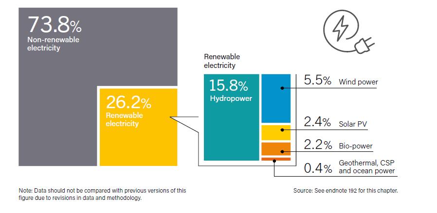
The sun as captured by Kalogirou, 2014, generates its energy through nuclear fusion of hydrogen nuclei to helium, which according to West (1993) converts 508 million tons of hydrogen into 504 million tons of helium every second, while the remaining 4 million tons of matter are converted to energy that makes the core temperature of the sun to be extremely hot. In order to ensure its structural stability, which it has maintained over the last 3 billion years, Almusaied et al, 2018 added that, the sun must radiate enough energy that is equal to the energy it produces. This stability over the last 3 billion years can be seen by the relative stability of the temperature of the earth’s surface. Being the source of most of the earth’s energy, solar radiation is the oldest form of energy known to mankind from prehistory, to be used in drying and preserving food, and in evaporating seawater to yield salt. The energy has also been harnessed to heat and cool buildings (both actively and passively), heat water for domestic and industrial uses, heat swimming pools, power refrigerators, operate engines and pumps, desalinate water for drinking purposes, generate electricity, for chemistry applications, and many more operations Kalogirou, 2014 reported the oldest large-scale application of solar energy when Archimedes, the Greek mathematician and philosopher (287–212 BC) used it to burn the Roman fleet in the bay of Syracuse. Thereafter, as man progresses in civilization and economic development, solar energy began to power solar furnaces capable of melting iron, copper, and other metals were made of polished iron, glass lenses, and mirrors. Also, according to the Renewable 2019 Global Report, Solar Energy presently contribute about 2.4% of the global electricity production as shown in figure 4, while figure 5 shows that China is leading the world with Solar Energy Installation as at end 2018.
Figure 4: Estimated Renewable Energy Share of Global Electricity Production, End-2018
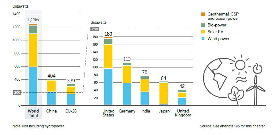
Figure 5:
Renewable Power Capacities in World, EU-28 and Top 6 Countries, 2018
2. DESCRIPTION
This section presents the fundamentals of solar radiation and how the radiation is converted to produce solar energy.
2.1 Fundamentals of Solar Radiation:
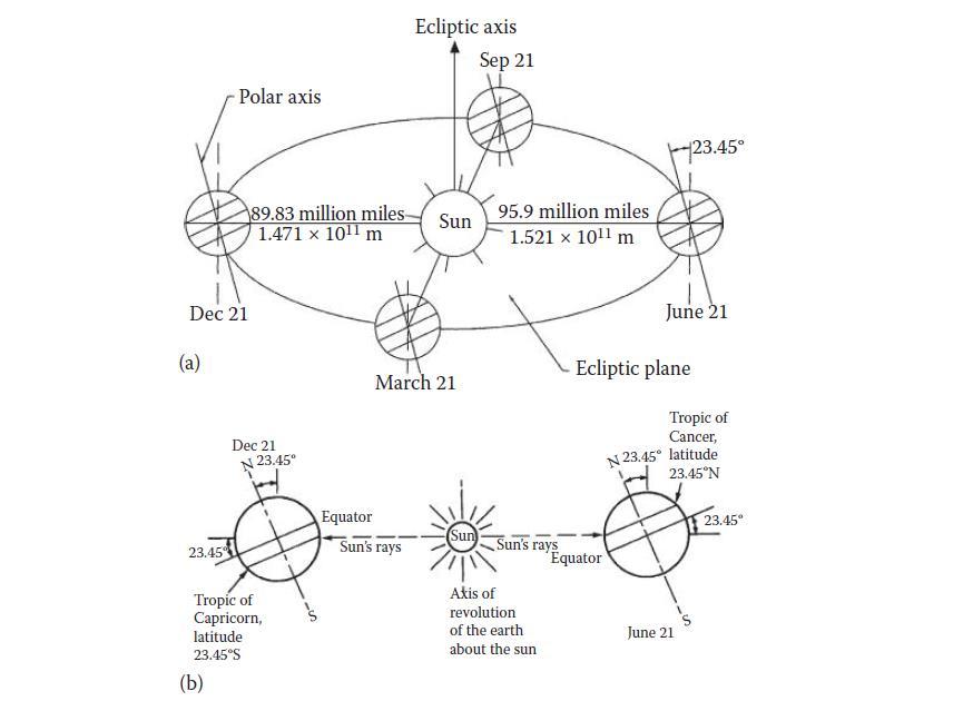
Considering the elliptical nature of the earth’s orbit around the sun as shown in figure 6, the sun’s radiation impact on the earth surface differs according to the time of the year, due to the changing distances between the sun and the earth. The minimum distance of 1.471 x 10¹¹ m is recorded during winter solstice at December 21, while the longest distance of 1.521 x 10¹¹m is recorded during summer solstice in June 21 with an all year-round average distance is is 1.496 × 10¹¹ m. The differing distances during the year impacts directly on the amount of solar radiation that is intercepted by the earth, with the maximum on December 21, and minimum on June 21. Besides the relative distances, the earth’s axis of rotation
International Journal of Engineering Research and Reviews ISSN 2348-697X (Online) Vol. 8, Issue 4, pp: (1-25), Month: October - December 2020, Available at: www.researchpublish.com
at an angle of 23.45° around the sun, also causes the seasonal variation of the solar radiation available at any location on the earth.
Figure 6: (a) Motion of the earth about the sun. (b) Location of tropics. Note that the sun is so far from the earth that all the rays of the sun may be considered as parallel to one another when they reach the earth. Source: Goswami, 2015.
Though the intensity of the radiation differs with time, the radiation is distributed over a band of wavelengths as shown in figure 7. The different wavelengths depict different solar applications.
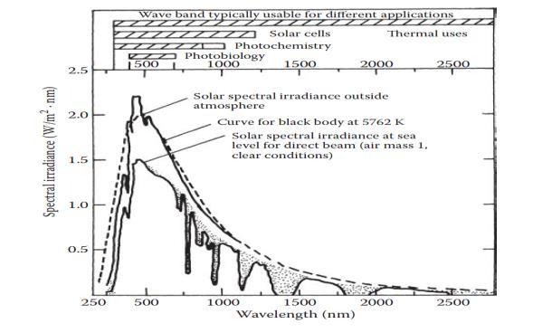
Figure 7: Radiation Wavelengths, and Spectral Irradiance curves outside atmosphere and at sea levels. Source. Goswami, 2015.
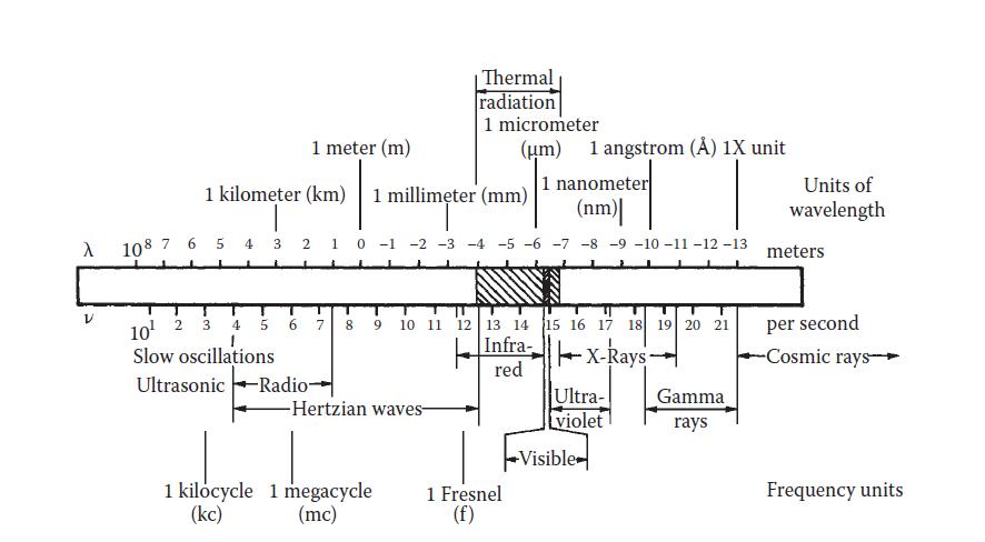
Figure 8 shows the electromagnetic spectrum with the different bands of wavelengths. The wavelengths are created due to changes in energy state when a body goes from a higher temperature to a lower energy state. Such changes are caused by the rearrangements in the electronic, rotational, and vibrational states of atoms and molecules, and because the rearrangements are associated with different energy changes due to differences in frequency, the radiation emitted by a body is distributed over a range of wavelengths. Solar radiation energy has wavelengths in the range between 0.3 and 3 µm, while thermal radiation ranges from 0.1 to 100 µm.
Figure 8: Electromagnetic Spectrum showing the bands of wavelengths. Goswami, 2015
Research Publish Journals
International Journal of Engineering Research and Reviews
ISSN 2348-697X (Online) Vol. 8, Issue 4, pp: (1-25), Month: October - December 2020, Available at: www.researchpublish.com
The solar radiation wavelength as shown by Kalogirou, 2014, is related to the speed at which all radiation travels, which is at the speed of light, and the frequency of radiation. Mathematically, the relationship is expressed as shown in equation 1: the speed of light is equal to the product of the wavelength and the frequency of radiation. The speed of light of a medium is the ratio of the speed of light in a vacuum to the refractive index of the medium as shown in Equation 1
C = λν = co Equation 1 n
where c is the speed of light in a medium (m/s); λ is the wavelength in meters (or micrometers [μm], 1 μm = 10−6 m), ν is the frequency (in s−1), co is the speed of light in a vacuum (m/s), and n is the index of refraction of the medium.
2.2. Solar Radiation Conversion
Solar radiation can be converted into useful energy, as electricity or as heat or as chemical energy into solar fuel (Jager et al (2014). This section emphasizes the conversion to electricity and solar thermal power.
2.2.1 Conversion into Electricity
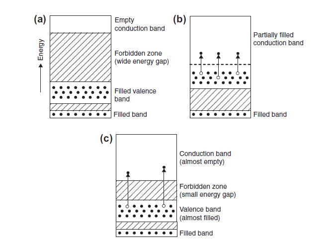
Solar energy can be converted into electricity directly through photovoltaics (PV) cells without any intervening heat engine PV cells also have the capacity of generating output as little as microwatts to megawatts, and therefore can be used in standalone devices such as calculators, watches, water pumping, remote buildings, communications, satellites and space vehicles, and even megawatt-scale power plants. (Goswami, 2015). Photovoltaic (PV) cells are constructed from semiconductors such as silicon (Si), Cadmium Sulfide (CdS), cuprous sulfide (Cu2S), and gallium arsenide (GaAs). Semiconductors are materials that only moderately conduct electricity (Kalogirou, 2014). There are two types of semiconductors, the pure ones, called intrinsic semiconductors, and those that are doped with small amounts of impurities, called extrinsic semiconductors. The Pure or Intrinsic Semiconductors are materials with partly filled valence bands and intermediate band gaps (≤3 eV). A valence band refers to the outermost electrons in an atomic structure, that determines how an atom interreacts with its neighbouring atom. Within the atomic structure, some valence bands, when excited, can jump farther away from the nucleus to form conductor band, which enables the material to conduct heat and electricity. The band gap thus refers to the energy difference between the valence band and the innermost subshell of the conduction band As shown in figure 9, Insulators are materials with full valence bands and high band gaps (>3 eV), while Conductors have relatively empty valence bands and may have some electrons in the conduction band.
Figure 9: Schematic diagrams of energy bands for typical materials. (a) Insulator. (b) Conductor (metal). (c) Semiconductor. Source: Kalogirou, 2014.
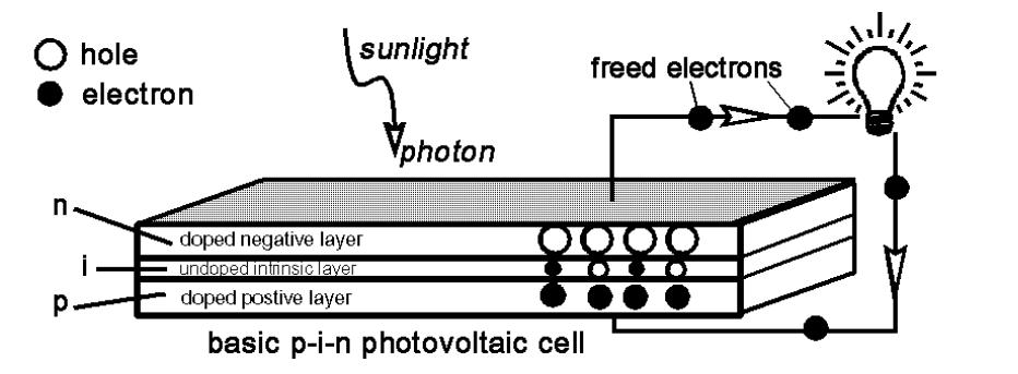
The extrinsic semiconductors are modified by introducing external impurities or doped to increase their conductivities. For instance, a silicon based semiconductor, with 4 valance electrons can be modified by introducing phosphorus with 5 valence electrons on the one side, that donates valence electrons to silicon to make it negative, or n-donor, while boron with 3 valence is introduced on the other side to create a greater affinity than silicon and thus making it positive or pdonor to the semiconductor. (European Commission, 2009). Figure 10 shows the photovoltaic effect upon the impingement of a photon on a PV cell.
International Journal of Engineering Research and Reviews ISSN 2348-697X (Online) Vol. 8, Issue 4, pp: (1-25), Month: October - December 2020, Available at: www.researchpublish.com
Figure 10: The photoelectric effect and PV cells diagrammed. Source: West, 1993
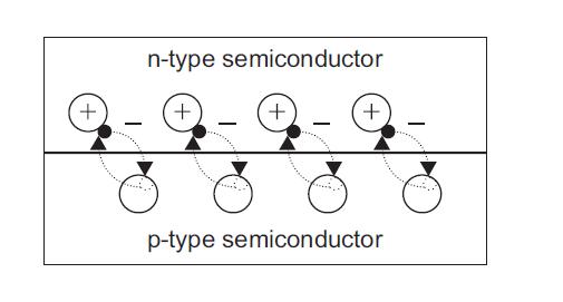
The p-type silicon which is in close contact with the n-type silicon, eventually forms a p-n junction as shown in figure 11, that permits a positive n-type electron to move to the negative electron, p-type, and become diffused and recombined with the holes on the p-type side. This creates a temporary imbalance of charge on either sides of the junction that creates a diode, that promotes current to flow in only one direction.
Figure 11: P-N Junction. Source: Kalogirou, 2014.
So, as shown in figure 10, when a light photon strikes a PV material, it can either be reflected, absorbed, or transmitted through the material. However, if the photon is absorbed by a valence electron, the energy electron is increased, and become excited where the photon energy is greater than the band gab of the semiconductor. The excited electron will now jump into the conduction band, where it can move freely as an electric field The atom loses an electron in the process through the p-n junction by an electric field across the PV material. In the case where the energy of the photon is less than that of the band gap, there will be no excitement of electrons, and hence no creation of electric field to move the electrons. The electrons will only recombine with the atom and cause an increase in temperature through kinetic energy. This further confirms that solar energy will be zero and the solar cell become inactive during darkness. During this period, it will work as a diode, i.e., a p–n junction that does not produce any current or voltage. It can however be connected to an external, large voltage supply, to generate a diode or dark current. Technically, one PV cell can only release one electron at a time as small as about 0.5 V, and so multiple cells are connected and encapsulated (usually glass covered) to form a module (also called a panel), and depending on the power requirement, several panels can be created and connected. One of the advantages of the modular structure is that additional panels can be added to an existing system as required. The modules in a PV system are usually connected in arrays with Mp parallel branches and Ms modules in series as shown in figure 12
Figure 12: PV Modules arrangement in Arrays. Source: Kalogirou, 2014.
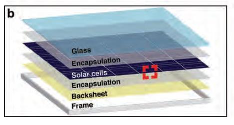
According to Schmalensee etal (2015), a typical silicon (Si) PV module as shown in figure 13, consists of a glass sheet for mechanical support and protection, laminated encapsulation layers of ethylene vinyl acetate (EVA) for ultraviolet (UV) and moisture protection; 60 to 96 individual 6-inch-square (15-cm-square) solar cells, each capable of producing 4–5 watts under peak illumination (Wp); a fluoropolymer backsheet for further environmental protection; and an aluminum frame for mounting. Common module dimensions are 1 meter by 1.5 meters by 4 centimeters, and peak power ratings range from 260 W to 320 W.
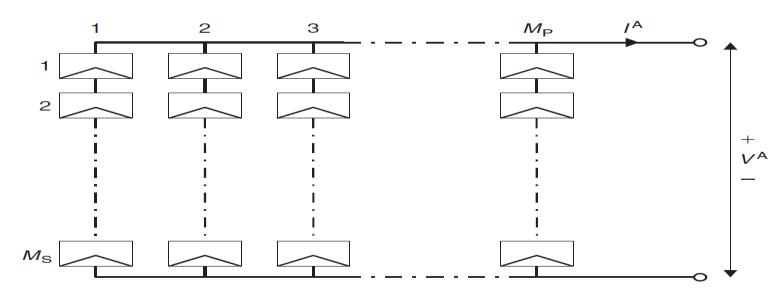
Figure 13: A

Typical
Breakout view of a PV Module. Source: Schmalensee etal (2015).
Solar cells are of varying types, but the two main types are the Wafer based Silicon type, and Thin-filmed type of which the Wafer type constitute more than 90 % of the solar cells currently made worldwide These types, which are approximately 200 μm in thickness, are fabricated on semiconducting wafers with no additional substrate These solar cells, which are also called mono-crystalline or multi-crystalline silicon solar cells, are either cut from a single crystal rod or from a block composed of many crystals The second type is based on Thin-films, which are approximately 1-2 μm thick and therefore require significantly less active, semiconducting material. The thin-film cells consist of layers of semiconducting material deposited onto an insulating substrate, such as glass or flexible plastic. The thin-film types are of lower efficiencies than wafer-based silicon solar cells, which means that more exposure surface and material for the installation is required for a similar performance (European Commission, 2009).
2.2.2 Solar Thermal Conversion
Solar thermal conversion occurs when a dark surface, solar collector, placed in sunshine absorbs solar energy and heats up, and then transfers part of the energy it absorbs to a working fluid in contact with it. Thermal power systems or also called the Concentrated solar power (CSP), generates electricity by using sunlight to heat a fluid, which is then used to create steam that drives a turbine-generator set. Unlike the PV system that generates direct electricity, the CSP would require a form of energy storage to be incorporated into the design of CSP plants, in order to generate electricity. This makes CSP system a potential source of ―dispatchable‖ renewable power. Schmalensee etal (2015). Solar thermal system relies on the absorptive capacity of the material used in constructing solar thermal collector, as that enables the surface to absorb a part of the radiation that increases the surface temperature. Besides the absorptive capacity, the efficiency of any surface as a solar collector also depends on how the thermal and reradiation losses to the surroundings are minimized, and on how the energy from the collector is removed for useful purposes. This has thus limited the choice of materials required for solar collector to two types of special surfaces, the selective absorbers and reflecting surfaces. Selective absorber surfaces combine a high absorptance for solar radiation (short wavelengths) with a low emittance for the normal operating temperature of the surface The purpose of the absorber is to absorb as much of the incident solar radiation as possible, reemit as little as possible, and allow efficient transfer of heat to a working fluid. The materials used for absorber plates include copper, aluminium, stainless steel, galvanized steel, plastics, and rubbers. Copper seems to be the most common material used for absorber plates and tubes because of its high thermal conductivity and high corrosion resistance. However, copper is quite expensive. In order to increase the absorption of solar radiation and to reduce the emission from the absorber, the metallic absorber surfaces are painted or coated with flat black paint or some selective coating. A selective coating has high absorptivity in the solar wavelength range (0.3 to 3.0 μm). The other property is the Reflectance, which is particularly important for the design of focusing collectors. when a ray of incident radiation at an angle θ is reflected at the same polar angle and the azimuthal angles differ by 180°, as for a perfect mirror, the reflection is said to be specular. The reflection is said to be diffuse if the incident radiation is scattered equally in all directions. This is shown in figure 14
International Journal of Engineering Research and Reviews
ISSN 2348-697X (Online) Vol. 8, Issue 4, pp: (1-25), Month: October - December 2020, Available at: www.researchpublish.com
2.2.2.1Types of Solar Thermal Collectors
Solar energy collectors are special kinds of heat exchangers that transform solar radiation energy to internal energy of the transport medium. They do this by absorbing the incoming solar radiation, converts it into heat, and transfers the heat to a fluid (usually air, water, or oil) flowing through the collector. The solar energy collected is carried from the circulating fluid either directly to the hot water or space conditioning equipment or to a thermal energy storage tank, from which it can be drawn for use at night or on cloudy days. (Kalogirou, 2014). Six different types of solar collectors are known, and these are Flat-plate collector, High efficiency flat-plate collector, Fixed concentrator, Parabolic trough collector, Parabolic dish collector, and finally Central receiver
i. Flat Plat Collector
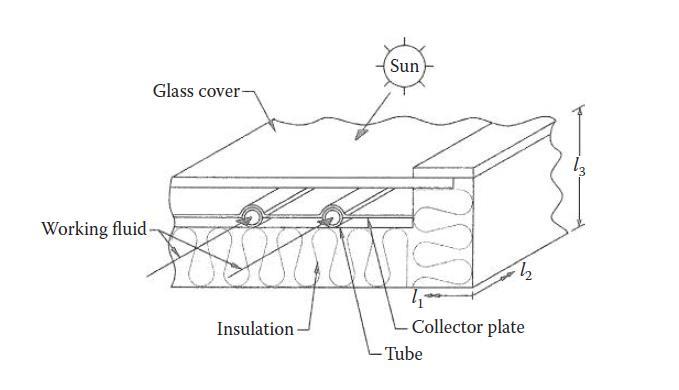
A simple flat-plate collector as shown in figure 15, consists of an absorber surface (usually a dark, thermally conducting surface); a trap for re-radiation losses from the absorber surface (such as glass, which transmits shorter-wavelength solar radiation but blocks the longer-wavelength radiation from the absorber); a heat-transfer medium such as air, water, and some thermal insulation behind the absorber surface. Flat-plate collectors are used typically for temperature ranges up to 75°C, although higher temperatures can be obtained from high-efficiency collectors. Flat plate collectors are of two basic types based on the heat-transfer fluid: Liquid type: where heat-transfer fluid may be water, mixture of water and antifreeze oil, and the Air type, where the heat-transfer medium is air (used mainly for drying and space heating requirements) They are thus more commonly used for agricultural drying and space heating applications. Their basic advantages are twofold: (1) low sensitivity to leakage and (2) there is no need for an additional heat exchanger for drying and space heating applications.
Figure 15: Schematics of a solar collector. Source: Goswami 2015. Technically, air has a relatively poor heat-transfer properties than water, especially, during turbulent flow condition in a given conduit for a fixed value of Reynolds number, the convection heat-transfer coefficient for water is approximately 50 times greater than that for air. As a result, if air must be used as the fluid, it is essential to provide the largest heat transfer area possible to remove heat from the absorber surface of an air heating collector, and this can be achieved by flowing air over the entire rear surface of the absorber Conventional simple flat-plate solar collectors have some limitations as they were developed for use in sunny warm climates, and as such performs poorly when conditions become unfavorable during cold, cloudy, and windy days. Furthermore, weathering influences, such as condensation and moisture, cause early deterioration of internal materials, resulting in reduced performance and system failure. This is where Tubular Solar Energy Collectors become relevant.
ii. Evacuated tube collectors (ETC)
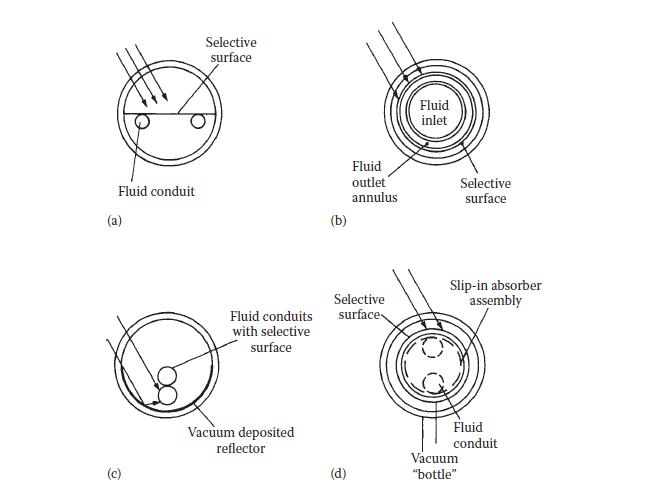
These types consist of a heat pipe inside a vacuum-sealed tube, and shows that the combination of a selective surface and an effective convection suppressor can result in good performance at high temperatures. The vacuum envelope reduces convection and conduction losses, so the collectors can operate at higher temperatures than FPCs. Like FPCs, they collect both direct and diffuse radiation, but their efficiency is higher at low incidence angles. This gives ETCs an advantage over FPCs in terms of daylong performance. ETCs use liquid–vapor phase change materials to transfer heat at high efficiency (Goswami 2015) Tubular collectors, with their inherently high compressive strength and resistance to implosion, afford the only practical means for completely eliminating convection losses by surrounding the receiver with a vacuum on the order of 10−4 mm Hg. Tubular collectors can also be used to achieve a small level of concentration (1.5 to 2.0) by forming a mirror from a part of the internal concave surface of a glass tube. This reflector can focus radiation on a receiver inside this tube. Since such a receiver is fully illuminated, it has no parasitic ―back‖ losses. (Kalogirou,2014)
International Journal of Engineering Research and Reviews ISSN 2348-697X (Online) Vol. 8, Issue 4, pp: (1-25), Month: October - December 2020, Available at: www.researchpublish.com
Figure 16: Evacuated-tube solar energy collectors: (a) flat plate, (b) concentric tubular, (c) concentrating, (d) vacuum bottle with slip-in heat exchanger contacting rear surface of receiver. Source: Goswami, 2015.
iii. Concentrating Solar Collectors.
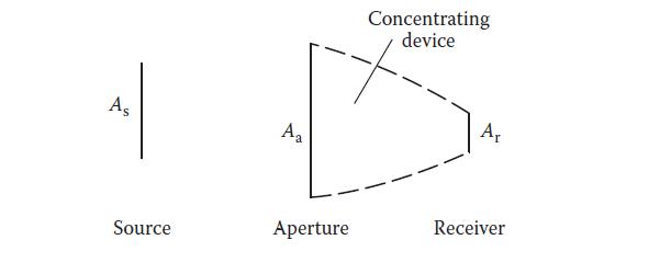
Another type of solar collectors are the concentrating solar collectors that work by concentrating the solar radiation over a relatively small area, thus increasing the energy delivery temperatures. It also reduces the areas of heat loss. Concentration can be obtained by reflection or refraction of solar radiation using mirrors or lenses. The reflected or refracted light is concentrated in a focal zone, thus increasing the energy flux in the receiving target. (Kalogirou, 2014). In terms of geometry, the concentration is achieved by reflecting or refracting the flux incident on an aperture area Aa onto a smaller receiver/absorber area Ar as shown in figure 17 Concentrators are inherently more efficient at a given temperature than Flat-Plate Collectors, since the area from which heat is lost is smaller than the aperture area. In a flatplate device, both areas are equal in size. One disadvantage of concentrators is that they can collect only a small fraction of the diffuse energy incident at their aperture. This property is an important criterion in defining the geographic limits to the successful use of concentrators. (Goswami, 2015).
Figure 17: Generalized schematic of any two-dimensional solar energy concentrating device showing source of radiation As, aperture Aa, and receiver Ar areas. Source: Goswami, 2015
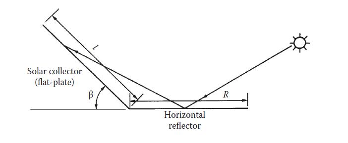
Concentrators are of two broad types, the Fixed Concentrators and the Parabolic Trough Concentrator A simple fixedconcentrator concept is based on using flat reflectors to boost the performance of a flat-plate collector as shown in Figure 18
Figure 18: Horizontal reflecting surface used to boost flat-plate collector performance. Source: Goswami, 2015
For higher concentrations, spherical or parabolic reflecting or refracting surfaces are used. The most common commercially available solar concentrator is the parabolic trough concentrator (PTC) shown in figure 19
International Journal of Engineering Research and Reviews
ISSN 2348-697X (Online) Vol. 8, Issue 4, pp: (1-25), Month: October - December 2020, Available at: www.researchpublish.com
Figure 19: Parabolic Trough Concentrator. Source: Kalogirou, 2014.

When the parabola is pointed toward the sun, parallel rays incident on the reflector are reflected onto the receiver tube. The concentrated radiation reaching the receiver tube heats the fluid that circulates through it, transforming the solar radiation into useful heat. PTC collectors usually track the sun with one degree of freedom using one of three orientations: east–west, north–south, or polar. Systems with light structures and low-cost technology for process heat applications up to 400 C could be obtained with PTCs. PTCs can effectively produce heat at temperatures between 50 and 400C. (Kalogirou, 2014)
iv. Paraboloidal Solar Collectors.
Another type of solar concentrators, the Paraboloidal solar collectors, track the sun radiation as the sun moves across the earth surface. This is achieved by the altazimuth method, which requires the tracking device to turn in both altitude and azimuth, that is, when performed properly, this method enables the concentrator to follow the sun exactly. (Kalogirou, 2014). These concentrators, according to Goswami, 2015, require a tracking device with two degrees of freedom, and uses devices with concentration ratios above 50, such as spherical mirror, CR = 50–150; paraboloidal mirror, CR = 500–3000; Fresnel lens, CR = 100–1000; and Fresnel mirror, CR = 1000–3000, where Concentration ratio is defined as geometric concentration ratio CR is based on the areas, or CR = Aa/Ar., aperture area Aa onto a smaller receiver/absorber area Ar. aperture area Aa onto a smaller receiver/absorber area Ar. Concentration ratio can vary over several orders of magnitude, from as low as slightly above unity to high values on the order of 10,000. Increased ratios mean increased temperatures at which energy can be delivered
v. Parabolic Dish Reflector (PDR).
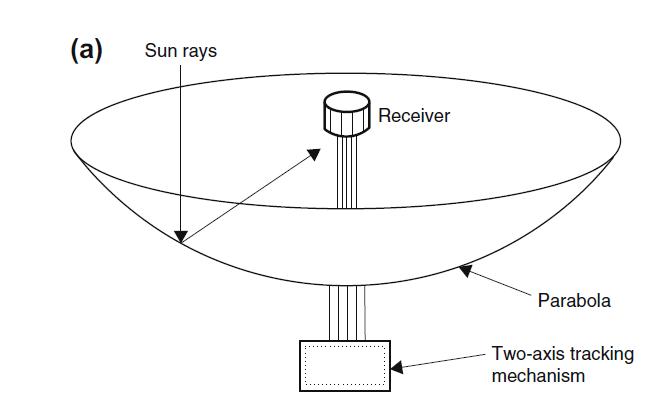
Finally, there is the parabolic dish reflector (PDR), as shown in figure 20 that acts as a point-focus collector that tracks the sun in two axes, concentrating solar energy onto a receiver located at the focal point of the dish. The PDR is like the Paraboloidal solar collectors as it tracks the sun radiation in two axes, so that the dish can fully track the sun to reflect the beam into the thermal receiver. The receiver absorbs the radiant solar energy, converting it into thermal energy in a circulating fluid, which can either be converted into electricity using an engine–generator coupled directly to the receiver or transported through pipes to a central power conversion system. Parabolic dish reflectors can achieve temperatures in excess of 1500 C.
3. GENERAL ANALYSIS
Designing an efficient and economic solar system will require detailed information about solar radiation availability at any location This section therefore presents the different types of solar radiation, how to measure the radiations, and how ensure longer energy availability through efficient energy storage.
International Journal of Engineering Research and Reviews
ISSN 2348-697X (Online) Vol. 8, Issue 4, pp: (1-25), Month: October - December 2020, Available at: www.researchpublish.com
3.1 Solar Radiation
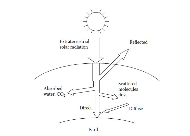
Solar radiation is an electromagnetic radiation from the sun distributed over different wavelengths, called Spectrum as earlier shown in figure 8, with solar radiation falling between 0.3-3µm in wavelength. As the primary energy source, global solar radiation is of significant economic importance especially in the energy transition to renewable energy sources. Besides the need for a successful design and effective utilization of solar energy systems and devices for application in various facets of human needs, such as power and water supply for industrial, agricultural, domestic uses and photovoltaic cell, global solar radiation information is also relevant in providing energy for Earth’s climatic system. The solar radiation information is also required in the forecast of the solar heat gain in building, weather forecast, agricultural potentials studies and forecast of evaporation from lakes and reservoir. All of these are dependent largely on the availability of information on solar radiation characteristic of each location where the system and devices are to be situated. (Falayi & Rabiu, 2012). Solar radiation is broadly categorized into extra-terrestrial and terrestrial radiation as shown in figure 21. Extra-terrestrial solar radiation are rays of the sun outside the atmosphere of the earth, while terrestrial solar radiation is extra-terrestrial radiation that passes through the atmosphere that strikes the earth surface.
Figure 21: Terrestrial and Extraterrestrial Solar Radiation. Source: Goswami, 2015.
3.1.1 Extra-terrestrial Solar Radiation
These are radiations outside of the earth’s atmosphere According to Widen and Munkhammar (2019), solar radiation levels in the solar system drop with the square of the distance to the Sun, and therefore the average amount of solar radiation falling on a surface normal to the rays of the sun outside the atmosphere of the earth at the mean earth-sun distance has been estimated to be 1367 W/m2, and this is called the Solar Constant. Estimates of the solar constant, Gsc have gradually improved by radiation measurements outside the atmosphere using aircraft, ballons and spacecraft. The value 1367 W/m2, adopted by the World Radiation Center (WRC), is commonly used in the solar engineering literature
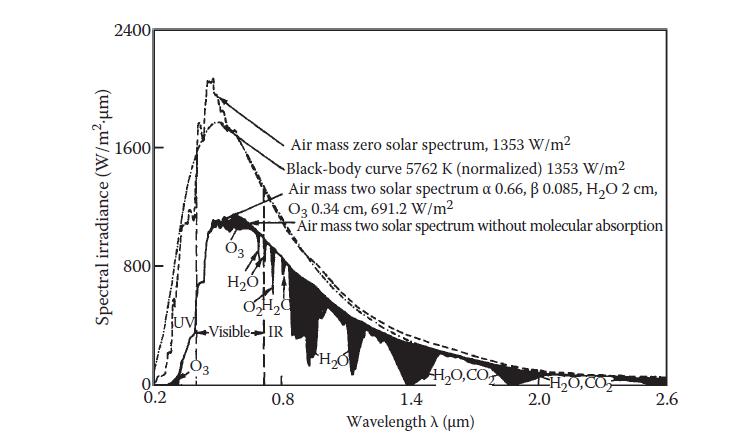
Figure 22: Extraterrestrial solar radiation spectral distribution. Also shown are equivalent black-body and atmosphere-attenuated spectra. Source: Goswami, 2015.
Figure 22 shows the spectral distribution of the extraterrestrial solar radiation, and according to Widen and Munkhammar (2019) due to Earth's elliptic orbit around the Sun the actual solar radiation outside the atmosphere at a given time (the extraterrestrial radiation) will differ from Gsc. Over the year, it varies from 1412 W/m2 at the beginning of July to 1322
International Journal of Engineering Research and Reviews ISSN 2348-697X (Online) Vol. 8, Issue 4, pp: (1-25), Month: October - December 2020, Available at: www.researchpublish.com
W/m2 at the turn of the year; a 3.3% variation from the mean value. This can be expressed mathematically in Equation 2 as where d is the day of the year. The subscript 0 denotes zero air mass (AM0) and the subscript n indicates that the radiation is on a plane normal to the Sun-Earth axis.
3.1.2 Terrestrial Solar Radiation
As extraterrestrial solar radiation passes through the atmosphere, a part of it is reflected back into space, a part is absorbed by air and water vapor, and some gets scattered by molecules of air, water vapor, aerosols, and dust particles (Figure 22). According to Widen and Munkhammar (2019) scattering occurs when the radiation interacts with air molecules, water and dust in the atmosphere. The degree of scattering is determined by the wavelength of the radiation in relation to particle size, the concentration of particles in the atmosphere and the total mass of air that the radiation has to travel through. The most important process is Rayleigh scattering, in which light is scattered off air molecules. On the other hand, absorption of solar radiation occurs in the UltraViolet range due to ozone and in the InfraRed range due to water and carbon dioxide. In the process of absorption, the solar radiation is converted to heat, which is emitted by the particles as long-wave radiation (Widen and Munkhammar (2019) The part of solar radiation that reaches the surface of the earth with essentially no change in direction is called direct or beam radiation The scattered diffuse radiation reaching the surface from the sky is called the sky diffuse radiation Widen and Munkhammar (2019) added that in contrast to beam radiation, which has a well-defined direction, diffuse radiation originates from all over the sky dome. Although diffuse radiation is most intense near the Sun, a good approximation is to assume that it is isotropic, i.e., uniformly distributed on all directions. The proportions of diffuse and beam radiation are strongly dependent on weather conditions. In sunny weather with clear skies, some 10-20% of the radiation is diffuse. In cloudy weather with a lack of bright sunshine most of the incident radiation is diffuse. A third radiation component that has to be considered in solar energy applications, Widen and Munkhammar (2019 further added, is radiation reflected from the ground and from other surrounding objects onto a sloped surface. It depends on the reflectivity of the ground, the so-called albedo. Goswami, 2015, stated that although extraterrestrial radiation can be predicted with certainty, radiation levels on the earth are subject to considerable uncertainty resulting from local climatic interactions. The most useful solar radiation data are based on long-term (30 years or more) measured average values at a location, which unfortunately are not available for most locations in the world. For such locations, an estimating method (theoretical model) based on some measured climatic parameter may be used.
3.2 Measurement of Solar Radiation
Accurate knowledge of the value of solar radiation is of critical in order to design optimal solar energy systems. Applications such as photovoltaics, photochemical, and daylighting therefore require knowledge of spectral (wavelength specific) or band (over a wavelength range, e.g., ultraviolet, visible, infrared) values of solar radiation. This section therefore describes some of the methods of measuring solar radiation Solar energy is primarily an electromagnetic radiation with the wavelengths ranging from approximately 0.3 μm (10−6 m) to over 3 μm, which correspond to ultraviolet (less than 0.4 μm), visible (0.4 and 0.7 μm), and infrared (over 0.7 μm). Most of this energy is concentrated in the visible and the near-infrared wavelength range The incident solar radiation, sometimes called insolation, is measured as irradiance, or the energy per unit time per unit area (or power per unit area). The units most often used are watts per square meter (W/m2), British thermal units per hour per square foot (Btu/h・ft2), and Langleys per minute (calories per square centimeter per minute, cal/cm2・min). Goswami, 2015, stated that long-term measured data of solar radiation are available for a large number of locations in the world, however, where longterm measured data are not available, various models based on available climatic data are used to estimate the solar radiation. Boxwell, 2017 also explained that solar energy is a combination of the hours of sunlight at a particular site and the strength of that sunlight, which ofcourse varies depending on the time of year and the location. This combination of hours and strength of sunlight is what is called solar insolation or solar irradiance, and the results can be expressed as watts per square metre (W/m²) or, more usefully, in kilowatt-hours per square metre spread over the period of a day (kWh/m²/day). Boxwell (2017) further explained that the knowledge of the solar irradiance for a particular location quoted as a daily average (i.e. the number of kilowatt-hours per square metre per day), can be used to estimate the daily amount of energy from a solar panel, by multiplying this figure by the wattage of the solar panel.
International Journal of Engineering Research and Reviews ISSN 2348-697X (Online) Vol. 8, Issue 4, pp: (1-25), Month: October - December 2020, Available at: www.researchpublish.com
3.3 Instruments for Measuring Solar Radiation and Sunshine
There are two basic types of instruments used to measure solar radiation, and these are the pyranometer and the pyrheliometer as shown in figure 23.
Figure 23: A schematic illustration

of a pyranometer
(a) and a pyrheliometer (b). Source: Widen and Munkhammar (2019)
A pyranometer has a hemispherical view of the surroundings and therefore is used to measure total, direct, and diffuse solar radiation on a surface. A pyrheliometer, on the other hand, has a restricted view (approximately 5°) and is, therefore, often used to measure the direct or beam solar radiation by pointing it toward the sun. Pyranometers are also used to measure the sky diffuse radiation by using a shadow band to block the direct sun view. A pyranometer consists of a flat sensor/detector with an unobstructed hemispherical view, which allows it to convert and correlate the total radiation incident on the sensor to a measurable signal. The pyranometers using thermal detectors for measurements can exhibit serious errors at tilt angles from the horizontal owing to free convection. These errors are minimized by enclosing the detector in double hemispherical high-transmission glass domes. The second dome minimizes the error attributed to infrared radiative exchange between the sensor and the sky. A desiccator is usually provided to eliminate the effect of condensation on the sensor or the dome. (Goswami, 2015).
A pyrheliometer on the other hand according to Widen and Munkhammar (2019), measures solar radiation coming directly from the Sun and a small portion of the sky around the Sun at normal incidence. In this device sunlight typically enters through a window to a thermopile (a device that converts heat to electricity). The electrical signal that is generated can be recorded and converted into W/m2. The window of the pyrheliometer acts as a fillter that only lets through sunlight in the 0.3-3µm range.
3.4 Empirical Equations for predicting the availability of solar radiation
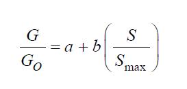
The average daily global radiation at a specific location can also be estimated using the knowledge of the average actual sunshine hours per day and the maximum possible sunshine hour per day at the location using Angstrom model which was modified by Prescott, as cited by (Falayi & Rabiu, 2012) and (Awasthi & Poudyal, 2018)
Equation 3

Where a and b are empirical constants, G is the monthly average of the daily global solar radiation on a horizontal surface at a location (KJ/m2-day), G0 is the average extraterrestrial radiation (KJ/m2-day). S is the monthly average of the actual sunshine hours per day at the location. Smax monthly average of the maximum possible sunshine hours per day, n is mean day of each month, and Gsc is the Solar Constant.
International Journal of Engineering Research and Reviews ISSN 2348-697X (Online) Vol. 8, Issue 4, pp: (1-25), Month: October - December 2020, Available at: www.researchpublish.com
Equation
Where δ is the solar declination angle, which is the angle that the Sun’s makes with equatorial plane at solar noon It varies from 23.45o on June 21 to 0o on September 21 to -23.45o on December 21, to 0o on March 21. It is estimated with the following equation:
Ф is the observer angle.
Ws = cos -1( tan Фtan δ), is the hour angle at sun set, which is positive during the morning, reduces to zero at solar noon and increasingly negative when the afternoon progresses
3.5 Thermal Storage
Given the variability of the solar energy, because of the seasonal, diurnal, and intermittent nature of solar energy it is critical that solar energy be stored to preserve the energy for all seasons in order to match the demand – supply equilibrium. This can also be seen in nature, as nature provides storage of solar energy in several ways, such as plant matter, also known as biomass, ocean thermal energy, and hydro-potential at high elevation by evaporation from water bodies and subsequent condensation. Technically, fossil fuels are a stored form of solar energy because they are produced from biomass. Since solar energy availability varies by the time of the day and also by the time of the year (seasonal), and can also fluctuate even during a day owing to clouds, energy storage systems according to Goswami, 2015, can be short term or long term depending on the objectives, which can be one of four reasons:
1. Buffering with the objective of overcoming cloudiness for short periods from a few minutes to a couple of hours,
2. Delivery Period Displacement, such as collection during the day for delivery during peak load period of evening hours,
3. Delivery Period Extension by storing enough during the day to have storage available for hours before sunrise and after sunset or even for longer times of non-sunshine hours of a day to several days, and
4. Seasonal Storage, which would store heat during summer for usage during winter.
Three parameters are important in any energy storage system, and these are the duration of storage, energy density (or specific energy), and the charging and discharging (storage and retrieval). Of these parameters, energy density determines the size of a storage system
3.5.1
Types of Energy Storage
According to Gowsami, 2015, thermal energy can be stored as sensible heat, as latent heat, or as the heat of chemical reaction (thermochemical)
a. Sensible heat, Q, is stored in a material of mass m and specific heat cp by raising the temperature of the storage material from T1 to T2 and is expressed by Equation 7
Equation 7
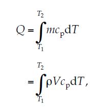

where ρ and V are density and volume of the storage material, respectively. For moderate temperature changes, such as for solar space and water heating systems, the density and specific heat may be considered constants Most common sensible heat storage materials are water, organic oils, rocks, ceramics, and molten salts The most common medium for storing sensible heat for use with low- and medium-temperature solar systems is water. Water is cheap and abundant and has a number of particularly desirable properties

International Journal of Engineering Research and Reviews ISSN 2348-697X (Online) Vol. 8, Issue 4, pp: (1-25), Month: October - December 2020, Available at: www.researchpublish.com
b. Latent Heat Storage, Thermal energy can also be stored as latent heat in a material that undergoes phase transformation at a temperature that is useful for the application. If a material with phase change temperature Tm is heated from T1 to T2 such that T1 < Tm < T2, the thermal energy Q stored in a mass m of the material is given by Equation 8;
Equation 8
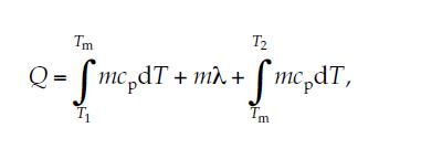
where λ is the heat of phase transformation. Four types of phase transformations useful for latent heat storage are as follows: solid ⇄ liquid, liquid ⇄ vapor, solid ⇄ vapor, and solid ⇄ solid. Since phase transformation is an isothermal process, thermal energy is stored and received at a fixed temperature known as the transition temperature. Some common phase change materials (PCMs) used for thermal storage are paraffin waxes, non paraffins, inorganic salts (both anhydrous and hydrated), and eutectics of organic or inorganic compounds. For high-temperature storage, even metals may be used as PCMs
c. Thermochemical Energy Storage, Thermochemical energy can be stored as heat of reaction in reversible chemical reactions. In this mode of storage, the reaction in the forward direction is endothermic (storage of heat), while the reverse action is exothermic (release of heat). For example, A + ΔH ⇆ B + C. The amount of heat Q stored in a chemical reaction depends on the heat of reaction and the extent of conversion as given by Q = armΔH, where ar is fraction reacted, ΔH is the heat of reaction per unit mass, and m is mass. Chemical reaction is generally a highly energetic process. Therefore, a large amount of heat can be stored in a small quantity of a material. Another advantage of thermochemical storage is that the products of reaction can be stored at room temperature and need not be insulated. For sensible and latent heat storage materials, insulation is very important. Examples of reactions include decomposition of metal hydrides, oxides, peroxides, ammoniated salts, carbonates, sulfur trioxide, and so on
4. ACTUALIZATION
This section presents the application of Solar Energy in electricity and heating systems
4.1 Electricity Generation.
There are two basic approaches to solar electric power generation. One is by photovoltaic (PV) process, a direct energy conversion, while the other approach is to convert sunlight to heat at high temperatures and then heat to mechanical energy by a thermodynamic power cycle and, finally, convert the mechanical energy to electricity. Though 97% of Solar Electricity is through PV cells, we have presented both methods of electricity generation in this section.
4.1.1 Photovoltaic Process (PV)
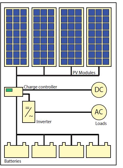
This process has three main systems, the stand-alone, grid-connected, and the hybrid system, though the basic PV system principles and elements remain the same. Systems are adapted to meet particular requirements by varying the type and quantity of the basic elements. Figure 24 shows a typical standalone PV electrical system
International Journal of Engineering Research and Reviews
ISSN 2348-697X (Online) Vol. 8, Issue 4, pp: (1-25), Month: October - December 2020, Available at: www.researchpublish.com
Stand-alone systems rely on solar power only. These systems can consist of the PV modules and a load only or they can include batteries for energy storage. When using batteries, charge regulators are included, which switch off the PV modules when batteries are fully charged, and may switch off the load to prevent the batteries from being discharged below a certain limit. The batteries must have enough capacity to store the energy produced during the day to be used at night and during periods of poor weather. Figure 25 shows a PV system with a Grid connection.
Figure 25: Grid
Connected
PV System. Source: Jager et al, 2014
Grid-connected PV systems have become increasingly popular for building integrated applications. These PV systems are connected to the grid via inverters, which convert the DC power into AC electricity. In small systems as they are installed in residential homes, the inverter is connected to the distribution board, from where the PV-generated power is transferred into the electricity grid or to AC appliances in the house. These systems do not require batteries, since they are connected to the grid, which acts as a buffer into which an oversupply of PV electricity is transported while the grid also supplies the house with electricity in times of insufficient PV power generation. Large PV fields act as power stations from which all the generated PV electricity is directly transported to the electricity grid. They can reach peak powers of up to several hundreds of MWp.
Figure 26: Hybrid PV System. Source: Jager et al, 2014
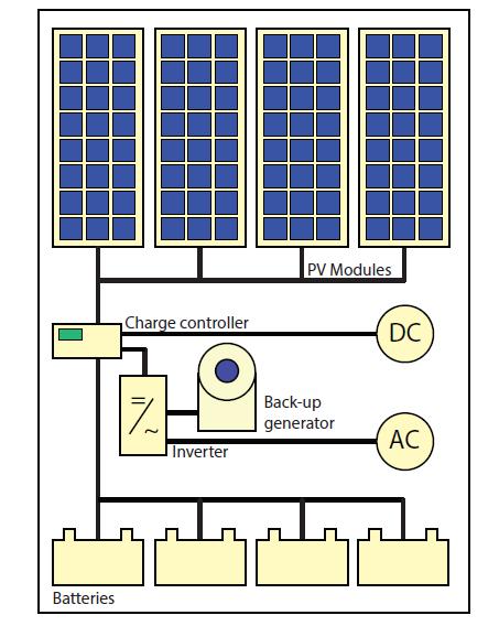
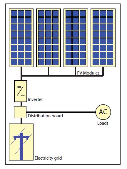
Figure 26 shows a fully Hybrid systems which consist of combination of PV modules and a complementary method of electricity generation such as a diesel, gas or wind generator. In order to optimise the different methods of electricity generation, hybrid systems typically require more sophisticated controls than stand-alone or grid-connected PV systems. For example, in the case of an PV/diesel system, the diesel engine must be started when the battery reaches a given discharge level and stopped again when battery reaches an adequate state of charge. The back-up generator can be used to recharge batteries only or to supply the load as well.
Regardless of the configuration, PV electrical system have some common components such as PV Modules, Inverters, Batteries, and Charge Controller. PV modules are combination of solar cells, which can also be connected to form Solar
International Journal of Engineering Research and Reviews
ISSN 2348-697X (Online) Vol. 8, Issue 4, pp: (1-25), Month: October - December 2020, Available at: www.researchpublish.com
Arrays for more electric power generation. The batteries are to store solar energy, while an Inverter or DC-AC converters are used in grid connected systems to convert the DC electricity originating from the PV modules into AC electricity that can be fed into the electricity grid. There is also a Charge Controller, sometimes referred to as a photovoltaic controller or battery charger, which is only necessary in systems with battery back-up. The primary function of a charge controller is to prevent overcharging of the batteries. Most also include a low voltage disconnect that prevents over-discharging batteries. In addition, charge controllers prevent charge from draining back to solar modules at night. Some modern charge controllers incorporate maximum power point tracking, which optimizes the PV array’s output, increasing the energy it produces. (Jager et al 2014).
4.1.2 Solar Thermal Power- Electricity
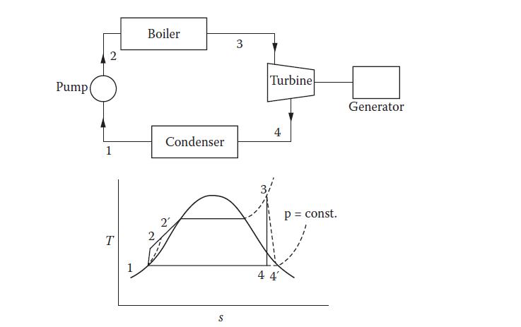
The second approach is to convert sunlight to heat at high temperatures and then heat to mechanical energy by a thermodynamic power cycle and, finally, convert the mechanical energy to electricity. Most of the thermal power production in the world is based on Rankine cycle and, to a smaller extent, Brayton cycle Normally, water is the working fluid for the Rankine cycle. However, for lower-temperature solar collection systems (70°C to approximately 300°C), organic fluids are used, in which case the cycle is commonly referred to as the organic Rankine cycle (ORC). Figure 27 is a schematic of the Rankine Cycle with a temperature–entropy (T–s) diagram for steam as a working fluid.
Figure 27: Rankine Cycle with a temperature–entropy (T–s) diagram for steam as a working fluid. Source: Goswami, 2015.
The typical process in a Rankine Cycle as shown in figure 27 is described below:
1–2 Saturated liquid from the condenser at state 1 is pumped to the boiler at state 2 isentropically.
2–3 Liquid is heated in the boiler at constant pressure. The temperature of the liquid rises until it becomes a saturated liquid. Further addition of heat vaporizes the liquid at constant temperature until all of the liquid turns into saturated vapor. Any additional heat superheats the working fluid to state 3.
3–4 Steam expands isentropically through a turbine to state 4.
4–1 Steam exiting the turbine is condensed at constant pressure until it returns to state 1 as saturated liquid.
Major components of a Rankine power plant include boiler, turbine, condenser, pumps (condensate pump, feedwater booster, and boiler feed pump), and heat exchangers (open heaters and closed heaters). All the components of a solar thermal power plant are the same as those in a conventional thermal power plant except the boiler. The boiler in a solar thermal power plant includes a solar collection system, a storage system, an auxiliary fuel heater and heat exchangers. Figure 28 shows a schematic representation of a solar boiler. The maximum temperature from the solar system depends on the type of solar collection system (PTCs, central receiver with heliostat field, parabolic dishes, etc.). If the temperature of the fluid from the solar system/storage is less than the required temperature for the turbine, an auxiliary fuel is used to boost the temperature. A fossil fuel or a biomass fuel may be used as the auxiliary fuel. A condenser is a large heat exchanger that condenses the exhaust vapor from the turbine
International Journal of Engineering Research and Reviews ISSN 2348-697X (Online) Vol. 8, Issue 4, pp: (1-25), Month: October - December 2020, Available at: www.researchpublish.com
Figure 28: Solar Boiler System. Source: Goswami, 2015.

Figure 29: Schematic diagram of a solar thermal energy conversion system. Source: Kalogirou, 2014.
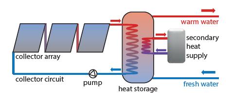
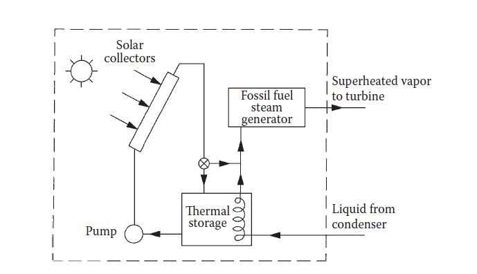
Figure 29 shows the process of solar thermal conversion into electricity generation. The process involves using concentrated mirrors to collect sunlight to create heat, then the heat is used to create steam, which is used to drive turbines and generators, just like in a conventional power station. Such plants have been operating successfully in California since the mid-1980s and currently provide power for about 100,000 homes. Recently, a CSP plant, called Nevada Solar I, started operating in Nevada, and another two called PS10 (10 MW) and PS20 (20 MW) started operating in Spain, and more CSP plants are under construction in several other countries of the world. Apparently, the Spanish government has realized the huge potential of the CSP industry and is subsidizing the electricity produced with a feed-in tariff scheme. PS10 and PS20 together provide electricity for 200,000 homes. The main technologies used in CSP plants are the parabolic trough collectors, power towers, and dish/Stirling-engine systems. (Kalogirou, 2014).
4.2 Other Applications of Solar Thermal Power
Solar thermal energy, besides generation of electricity, has various applications such as space heating, water heating, and solar air conditioning, or solar cooling, which are presented in this section.
4.2.1 Solar Water Heating
A solar water heater is a combination of a solar collector array, an energy transfer system and a storage tank, as sketched in Figure 30. The main part of a solar water heater is the collector array, which absorbs solar radiation and converts it into heat. This heat is absorbed by a heat transfer fluid that passes through the collector. The heat can be stored or used directly. The amount of the hot water produced by a solar water heater throughout a year depends on the type and size of the solar collector array, the size of the water storage, the amount of sunshine available at the site and the seasonal hot water demand pattern.
Figure 30: Solar Water Heating System. Source: Jager et al 2014
International Journal of Engineering Research and Reviews ISSN 2348-697X (Online) Vol. 8, Issue 4, pp: (1-25), Month: October - December 2020, Available at: www.researchpublish.com
4.2.2 Solar Cooling System
Solar cooling systems can be classified into two main categories according to the energy used to drive them: solar thermal cooling systems and solar electric cooling systems. In solar thermal cooling systems, the cooling process is driven by solar collectors collecting solar energy and converting it into thermal energy, and uses this energy to drive thermal cooling systems such as absorption, adsorption, and desiccant cycles; whereas in solar electric cooling systems, electrical energy that is provided by solar photovoltaic (PV) panels is used to drive a conventional electric vapor compressor airconditioning system. Both types of solar cooling can be used in industrial and domestic refrigeration and air-conditioning processes, with up to 95% saving in electricity Figure 31 from Ajib and Alahmer (2018), shows a typical absorption cooling system, with a generator as solar collectors
Figure 31: Schematic of the absorption chilling cycle: Source Ajib & Alahmer, 2018
The cycle starts with the absorber pumping the rich solution with coolant through the economizer, which is the heat exchanger to the generator. The generator are sets of solar collectors, which heats up the rich solution to drive out part of the coolant to flow to the condenser, while the remaining poor solution (poor on coolant) flows back to the absorber. In the condenser, the refrigerant vapor from the generator (solar collectors) condenses, with the heat of condensation rejected at an intermediate temperature level by cooling water from the cooling tower. The refrigerant condensate the flows back to the evaporator at low pressure through an expansion device. In the evaporator, the refrigerant is vaporized at very low pressure to produce the cooling power by extracting heat from the low-temperature medium. The coolant vapor flows to the absorber, where the refrigerant vapor is absorbed by the poor solution, which flows back from the generator through the economizer and the throttle, where the the heat of absorption and mixing is rejected by the cooling water stream supplied from a cooling tower. (Ajib & Alahmer, 2018). Another solar cooling system is the desiccant air-conditioning system which utilizes the capability of desiccant materials in removing the air moisture content by sorption process. All materials that attract moisture at different capacities are called desiccant The desiccant cooling system can be a suitable selection for thermal comfort especially in climates with high humidity (Ajib & Alahmer, 2018).
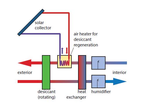
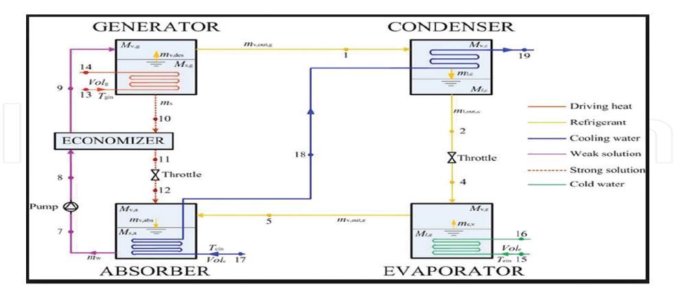
Figure 32: Desiccant cooling. Source: Jager et al 2014.
The system works by drying air as it passes through a desiccant, like silica. Then water is sprayed into the air, as the water evaporates, the air is cooled and humidified, such that it guarantees optimal interior conditions. Air that leaves the interior is heated up using a solar collector. The hot air streams through the desiccant. Hence, the desiccant is tried and can be reused for adsorbing humidity. (Jager, et al 2014)
International Journal of Engineering Research and Reviews
ISSN 2348-697X (Online) Vol. 8, Issue 4, pp: (1-25), Month: October - December 2020, Available at: www.researchpublish.com
5. DISCUSSIONS
The current energy transition will no doubt position renewables strategically in the global energy mix from 2040, with Solar and Wind Energy playing dominant roles in the energy mix. This will also require corresponding engineering and technological innovations in order to match the demand-supply equilibrium. This section therefore discusses some of the challenges inherent in the solar energy segment, being the subject of this paper, and the advancements so far reached in ensuring a stable and efficient solar energy system and consolidates its role in the global future energy mix. According to the World Bank (2019), solar technology is revolutionizing the power sector, and can easily become a game changer for many developing countries as solar is (i) wide-spread promoting energy security, (ii) among the cheaper source of electricity and cost-competitive with fossil fuel in many countries, (iii) supporting universal access to electricity, (iv) enabling a short construction timeline, and (v) when combined with battery storage, providing firm power. The World Bank added that Renewable energy deployment at the necessary scale is hindered by critical challenges such as grid integration technical constraints, off-taker risk, and weak procurement and planning capacity. The bank also estimated that, based on the International Energy Agency’s (IEA) Sustainable Development Scenario, 950 gigawatts (GW) of solar photovoltaic (PV) and 580 GW of wind need to be installed in developing countries by 2025 Those targets represent increases of 690 GW of solar PV and 330 GW of wind from current installed capacity to be built within six years and an investment of over US$500 billion in solar PV and US$400 billion in wind.
5.1 Challenges with Solar Energy Operations
Solar Energy need to overcome several hurdles before it can truly replace fossil fuels for power generation, some of which are presented here. One of the key hurdles to the widespread adoption of solar power is variances in solar intensity as the energy output depends on the amount of solar energy the system receives. And given the inherent challenges with solar radiation through the atmosphere, this variability will pose a demand-supply problem, especially in areas of limited solar radiation. Another major obstacle is the efficiency of photovoltaic cells, as that significantly determines how much of the radiation can be converted and be usable. According to Kazmeyer (2018), the efficiency of most commercial solar panels is less than 25%. Kazmeyer (2018) also reported that while solar generation is emission-free, the manufacture of solar panels and related technologies can involve some environmentally unfriendly substances. Nitrogen trifluoride is a common byproduct of electronics manufacture, including those used in solar cells, and it is a greenhouse gas 17,000 times more potent than carbon dioxide. In addition, many solar cells include small amounts of the toxic metal cadmium, and the batteries required to store generated electricity can contain a host of other heavy metals and dangerous substances. Besides these environmental challenges, Carbeck,(2016) stated that the silicon solar cells that currently dominate the world market suffer from three fundamental limitations. The first major limitation of silicon photovoltaic (PV) cells is that they are made from a material that is rarely found in nature in the pure, elemental form needed. While there is no shortage of silicon in the form of silicon dioxide (beach sand), it takes tremendous amounts of energy to get rid of the oxygen attached to it. Typically, manufacturers melt silicon dioxide at 1500–2000 degrees Celsius in an electrode arc furnace. The energy needed to run such furnaces sets a fundamental lower limit on the production cost of silicon PV cells and also adds to the emissions of greenhouse gases from their manufacture Besides, this complex production processes, with its associated costs, Schmalensee, R etal (2015) added that wafer-type silicon also has low intrinsic light absorption that will require manufacturers to thicken silicon wafer, which ofcourse will contribute to increasing cost. Carbeck,(2016) further pointed out that this, thickening of the silicon makes them rather rigid and heavy. That Silicon PV cells work best when they are flat and housed in large, heavy panels, unfortunately, those panels according to Carbeck (2016), make large-scale installations very expensive, which is in part why these panel are always on rooftops and in big solar farms In designing equipment for solar energy utilization, Goswami, 2015, identified that the first problem that will confront the designer is the low flux density, that will require large surfaces to collect solar energy for large-scale utilization, which will also translate into higher costs. Another practical limitation identified by Goswami, 2015, that is not apparent from the macroscopic energy view is that most of the solar energy falls on remote areas and would therefore require some means of transmission to be useful to the industrialized nations. This is because, the mean amount of energy available on a horizontal plane is greatest in the continental desert areas around latitudes 25°N and 25°S of the equator and falls off toward both the equator and the poles. The highest annual mean irradiance is 300 W/m2 in the Red Sea area. Clouds reduce the mean global irradiance considerably in equatorial regions. However, whereas in northern climates the mean horizontal surface global irradiance varies from season to season, it remains relatively constant in equatorial regions. Typical values of mean annual
International Journal of Engineering Research and Reviews
ISSN 2348-697X (Online) Vol. 8, Issue 4, pp: (1-25), Month: October - December 2020, Available at: www.researchpublish.com
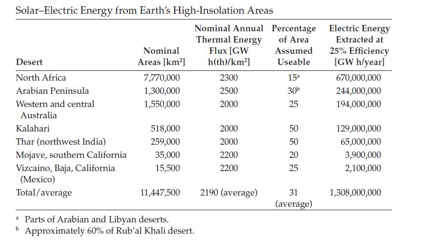
horizontal surface irradiance are as follows: Australia, approximately 200 W/m2; United States, 185 W/m2; United Kingdom, 105 W/m2. Table 1 presents the total solar electric energy potential for the solar energy– rich areas of the world. It is important to note that many of these parts of the world, for example, Saudi Arabia, central Australia, and parts of South Africa and India, are flat deserts that are practically unusable for agriculture.
Table 1: Total Solar Electric Energy Potentials.
Source: Goswami, 2015.
Goswami, 2015, also reported that solar energy as a large scale source of power and heat is affected by intermittency, caused by the daily variations owing to the rotating of the earth around its axis and a regular annual cycle owing to the inclination of the earth axis with the plane of the ecliptic and to the motion of the earth around the sun, and is also unavailable during periods of bad weather.
5.2 Challenges withSolarPowerGrid Integration
Energy from renewable sources is becoming a growing component of the electricity grid around the world, due to its contribution to achieving decarbonisation, energy security and improving the energy access. The integration of renewable energy resources into existing electrical grids is the way forward to achieve clean and sustainable power generation. Alshahrani et al (2019), however, noted that the intermittent renewable energy resources may be predictable, but they cannot be dispatched in a flexible way for meeting the fluctuating demand because their output cannot be altered quickly. Thus, most non-dispatchable electricity sources such as wind and solar are often highly intermittent, and these are two main types of non-dispatchable renewable energy that contribute noticeably to the electrical grid. One major challenge that renewables, such as Solar and Wind have is in their full integration with existing electricity grid, as most of the electric distribution systems are designed, operated and protected on the assumption that there is a single source of voltage on each distribution feeder. Khyani and Vajpai (2014) reported that renewable energy can be integrated into the grid either at the transmission level or distribution level, depending upon the scale of generation. That the larger generations systems such as wind farms are directly interconnected to the transmission system, while smaller distributed generation, such as small hydro, solar photovoltaics, biogas, biomass and small wind turbine, are generally interconnected to the medium or low voltage distribution systems. They also noted that regardless of where they are connected, both types of interconnections present different issues and challenges Khyani and Vajpai (2014) thus identified Technical, Contractual, Metering and Rates, Research and Development and Certification & Warranty issues as potential interconnection challenges. This paper, however, only addresses the technical issues. One of the issues is on safety, that, depending on the system design, some utility interconnected PV systems operate at DC voltages in excess of 300 volts before being inverted to standard alternating current. The potential fire hazard of DC at these voltages is greater than that of standard AC, because it is more difficult to extinguish a DC arc than an AC arc at the same voltage. Another technical concern is the power quality for utilities and customer-generators. Power should be consistently supplied at a standard voltage and frequency, because devices and appliances are designed to receive power at or near specified voltage and frequency parameters, and deviations may cause appliance malfunction or damage. Power quality problems can manifest themselves in lines on a TV screen or static noise on a radio, which is sometimes noticed when operating a microwave oven or hand mixer. A PV inverter can inject noise that can cause problems. In addition to simple voltage and frequency ranges, power quality standards also include harmonics, power factor, DC injection, and voltage flicker Alshahrani et al (2019) also noted additional technical problems of protection, since the straight protection scheme of each feeder in the distribution network was designed with the assumption that the feeder is radial, meaning the power flow is unidirectional.
International Journal of Engineering Research and Reviews
ISSN 2348-697X (Online) Vol. 8, Issue 4, pp: (1-25), Month: October - December 2020, Available at: www.researchpublish.com
However, the presence of PV systems on the feeder will cause bidirectional power flow resulting in the feeder no longer being radial, thus creating several problems to the current protection schemes used. When connecting high penetration levels of PV systems to the distribution network, it is necessary to address some aspects such as the protection of the generation equipment from internal fault, anti islanding protection and fault current protection of the distribution network Alshahrani et al (2019 further pointed out the problems of Voltage Stability, which relates to the ability of the power system to maintain at all the nodes its voltage levels at an acceptable level during normal operating conditions and after being encountered with a disturbance. Generally, voltage instability is a local phenomenon, but the widespread impact of, e.g., the voltage collapse of the entire system can happen as a result of the voltage instability. In addition, severe voltage collapse of the entire power system can be linked with rotor angle instability due to a gradual loss of synchronism, i.e. rotor angle separation of the traditional generators, which will result in a rapid voltage drop in the power system. They stated that the distinct characteristics of the PV system and the current grid codes will significantly affect the voltage stability of the system when large-scale PV systems are introduced to the transmission network of the grid Another technical challenge identified by Alshahrani et al (2019) is the problem of Rotor angle stability relates to the ability of the traditional synchronised generators in the grid to remain synchronised after being encountered with a disturbance. Normally, all the connected traditional generators to the grid are rotating at the same speed level, meaning the there is a balance between the mechanical input and the electromagnetic output of each traditional generator in the grid. However, a disturbance occurring would lead those traditional generators to accelerate or deaccelerate their rotating speed, affecting the angular position between the rotors, i.e. the balance between the mechanical input and the electromagnetic output. The grid can maintain the rotor angle stability if the difference between the rotor’s angular position is reduced until the synchronised speed level has been reached again. Otherwise, the rotor angle stability will be lost, resulting in the generator losing its synchronism with the rest of generators and leading to large fluctuations in its output in the form of power, voltage and current. Therefore, the grid system stability for any particular condition can be deduced by whether the deviations in the angular position of the rotors are capable of resulting in sufficient restoring torques. They further noted that the rotor angle stability is mainly affected by the topology of the power network, the mode that the grid operates at, the PV system’s capacity, its location and its control strategy. The PV system’s inability to cope with the fault ride-through may lead to it being off-grid, which would have a severe impact on the stability of the system, especially when there is a centralised large-scale PV system integrated to the grid. In addition, the integration of large-scale PV system into the grid will cause an alteration in the original grid power flow and the power of transmission channel, which means that, during fault ride-through of the PV system, it will present a different dynamic support characteristic compared to the conventional generators . Therefore, the aforementioned shows the importance of rotor angle stability, which should not be ignored when integrating the large-scale PV system to the grid. Finally, Alshahrani et all (2019) also reported the problems of frequency stability, which relates to the ability of the grid system to keep the frequency levels within its acceptable limits after being subjected to a disturbance, which results in the mismatch between the generation and the load. Generally, frequency stability issues are linked with the inadequate responses from components of the system, the insufficient generation reserve or the poor coordination of control and protection equipment Currently, the grid’s frequency is related to the rotating speed of the conventional synchronous generators in which the control of these generators manages the frequency by accelerating or deaccelerating them depending on the balance between the load and the power generated in order to increase or decrease the frequency. The PV technology lacks rotating machinery, i.e. inertial support, which together with its power variability causes problems in the grid in terms of frequency stability
5.3. InnovativeTechnical SolutionstoSolarEnergy
Several efforts to guarantee a reliable, sustainable and efficient solar energy delivery, especially in the area of electricity generation have been reported in the literature. Schmalensee, R etal (2015) in study recommended the use of the use of thin-film PV alternatives primarily cadmium telluride (CdTe) and copper indium gallium diselenide (CIGS) solar cells to tackle the challenges in the use of wafer-based crystalline silicon PV panels Though some commercial thin-film technologies are based on scarce elements, a number of emerging thin-film technologies use earth-abundant materials (even silicon in some cases), that show the potential of providing superior performance with lower manufacturing complexity and module cost. Other properties of some new thin-film technologies, such as low weight and compatibility with installation in flexible formats, offer promise for enabling reductions in costs along with lower module costs. Carbeck 2016 also reported a promising new way of making high-efficiency solar cells, using perovskites instead of silicon as part of the solutions to the wafer-based silicon PV cells Perovskites are a wide-ranging class of materials in which organic molecules, made mostly of carbon and hydrogen, bind with a metal such as lead and a halogen such as chlorine in a three-dimensional crystal lattice can be made much more cheaply and with fewer emissions. Manufacturers
International Journal of Engineering Research and Reviews
ISSN 2348-697X (Online) Vol. 8, Issue 4, pp: (1-25), Month: October - December 2020, Available at: www.researchpublish.com
can mix up batches of liquid solutions and then deposit the perovskites as thin films on surfaces of virtually any shape, no furnace needed. The film itself weighs very little. These features can eliminate another major limitation of silicon solar cells, which is their rigidity and weight. Perovskites have also been reported as the solution to overcome the limitation of conversion efficiency of conventional solar cells which has been stuck at 25 percent for 15 years. Carbeck 2016 , reported that Perovskite cells made of lead, iodide and methylammonium by 2009 which only converted less than 4 percent of the sunlight that hit them into electricity, with innovations by 2016, grew up to above 20 percent a five-fold improvement in just seven years and a stunning doubling in efficiency within just the past two years. They are now commercially competitive with silicon PV cells, and the efficiency limits of perovskites could be far higher still. Whereas silicon PV technology is now mature, perovskite PVs continue to improve rapidly. When paired with emerging battery technology, perovskite solar cells could help transform the lives of 1.2 billion people who currently lack reliable electricity. Carbeck, 2016, also reported that these emerging batteries are based on sodium, aluminium or zinc that are more affordable, more scalable, and safer than the lithium batteries currently used in advanced electronics and electric cars. They are also much better suited to support transmissions systems that rely heavily on solar or wind power. He therefore cited an example of such novel batteries deployed by the government of Indonesia to store 35 megawatts of solar panel capacity to 500 remote villages, that electrified the homes of 1.7 million people. The system is based on a zinc-air battery that can store up to 250 megawatt-hours of energy in order to provide reliable electricity regardless of the weather. Similar project was also initiated by the government of Madagascar to put 100 remote villages there on a solar-powered mini-grid backed by zincair batteries. In resolving the challenges of integrating solar power into the main grid, Alshahrani et al (2019) also reported the innovative energy storage system, such as these batteries, and the development of smart controls for the large-scale PV system. They opined that the integrated large-scale PV system should be capable of controlling the active power to provide frequency support to the grid, control the reactive power to provide voltage support to the grid and possess the fault ride through capability during various disturbances.
6. GENERAL RECOMMENDATIONS
Deploying a sustainable, efficient and cost-effective solar energy system that can play more significant roles in the global energy mix, will require consistent engineering and technological innovations. This is due to the inherent complexities associated with nature, especially as it affects the sun radiations, as highlighted in this paper, coupled with the technologies required to fully harness and to seamlessly deliver solar energy to end users. Some of the challenges, such as how to efficiently track and capture the sun’s radiation at all seasons, provide longer energy storage for continuous power delivery, sourcing for the raw materials that can produce efficient solar collectors and panels, and finally to seamlessly integrate solar powers to existing grid, requires both engineering and technological inventions. The reality is that, all these are predicated on consistent capital investments in Research and Development (R&D), a well-trained workforce, and an appropriate industrial establishment that can design, and then manufacture these tools and equipment. These prerequisites can readily deny poor and developing nations the opportunity to fully harness solar energy for their development. One other challenge is that not all countries are equally endowed in the natural distribution of these raw materials required for the manufacture of the tools and equipment. To therefore avoid any horse trading between resource endowed and resource deficit countries, there is need for more effective collaborations amongst developing nations to harness their resources in bringing these technologies to their remote villages, while the advanced and richer countries must subsidize the cost of producing the various components of this energy conversion system to make them accessible for poorer countries. Again, just as there are specific institutions for other energy systems, developing nations, and even the advanced countries must begin to support more research institutes and other tertiary colleges to research on more innovative technologies and to also train the needed human capital that will work on this new energy system. Finally, since trading on renewables is not fully developed like OPEC, however, because of its increasing relevance in the global energy equation, it is appropriate that renewables trading from raw materials, to intermediates and finished products be given appropriate attention.
7. CONCLUSION -A NEW PERSPECTIVE
The current global energy transition from predominantly fossil fuel driven economy to less carbon content renewables, will be anchored mostly on wind and solar energy sources. According to Alshahrani et al (2019, though wind energy conversion is more efficient than solar energy, the availability, unpredictability and variability of wind is harder to forecast, unlike solar energy which can easily be predicted: is only available during the day except when there are clouds Consequently, Solar electricity generation is one of very few low-carbon energy technologies with the potential to grow to very large scale. Therefore, massive expansion of global solar generating capacity to multi-terawatt scale is very likely an
International Journal of Engineering Research and Reviews
ISSN 2348-697X (Online) Vol. 8, Issue 4, pp: (1-25), Month: October - December 2020, Available at: www.researchpublish.com
essential component of a workable strategy to mitigate climate change risk Photovoltaic (PV) technology has undoubtably become one of the major sources of distributed renewable energy that has no limitation in supply It is predicted that, by 2040, PV technology will become the most significant electricity generation contributor among all other candidates of renewable energy. The emphasis therefore must be on proper engineering and technological interventions to provide a successful, efficient and sustainable solar energy system that can support the global economy. According to Schmalensee etal (2015) through there has been significant growth in installed solar generating capacity, great improvements in technology, price, and performance, and the development of creative business models that have spurred investment in residential solar systems., there is urgent need for further engineering and technological advances to enable a dramatic increase in the solar contribution at socially acceptable costs. To achieve these feats will ultimately require that solar technologies become cost-competitive with fossil generation, appropriately penalized for carbon dioxide (CO2) emissions, with most likely substantially reduced subsidies. This is where the technological advances must be backed up by policies that will encourage both government and private funding of R&D in innovative solar technologies, and to also establish Commercial frameworks that will facilitate trade and business transactions within the solar energy spectrum. The R&D is aimed at developing low-cost, scalable solar energy panels, collectors, storage and transmission and distribution technologies in order to achieve economic deployment of solar energy at large scale.
REFERENCES
[1] Almusaied, Z., Asiabanpour. B., and Aslan, S (2018): Optimization of Solar Energy Harvesting: An Empirical Approach, Hindawi, Journal of Solar Energy,Volume 2018, Article ID 9609735, 8 pages
[2] Alshahrani, A., Omer,S., Su, Y.,Mohamed, E and Saleh Alotaibi,S (2019): The Technical Challenges Facing the Integration of Small-Scale and Large-scale PV Systems into the Grid:A Critical Review Electronics 2019, 8, 1443, www.mdpi.com/journal/electronics
[3] Ajib, S and Alahmer, A (2018): Solar Cooling Technologies, Chapter 3, IntechOpen.https://api.intechopen.com/ chapter/pdf-preview/33347
[4] Awasthi, J and Poudyal, K.N (2018): Estimation of Global Solar Radiation Using Empirical Model on Meteorological Parameters at Simara Airport, Bara, Nepal, Journal of the Institute of Engineering, 2018, 14(1): 143-150
[5] Boxwell, M (2017): Solar Electricity handbook, Greenstream Publishing, UKhttp://www.sabz-energy.com/solar %20electricity%20handbook%202017.pdf, retrieved 8/3/2020
[6] Carbeck, J. (2016): Solar power has big limitations. This wonder material could change that World Economic Forum, https://www.weforum.org/agenda/2016/06/perovskite-solar-cells/
[7] European Commission (2009): Photovoltaic Solar Energy, Development and current research.
[8] Falayi, E.O and Rabiu, A.B (2012): Solar Radiation Models and Information for Renewable Energy Applications, http://www.intechopen.com/books/solar-radiation/solar-radiation-models-and-information-for-renewableenergyapplications
[9] Goswami, D.Y (2015): Principles of Solar Engineering, Third Edition, CRC Press, Taylor & Francis Group,
[10] Jäger, K., Isabella, O., Smets, A.H.M., René A.C.M.M. van Swaaij, Zeman, M., (2014): Solar Energy, Fundamentals, Technology, and Systems, Delft University of Technology
[11] Kalogirou, S.A (2014): Solar Energy Engineering Processes and Systems, Second Edition, 2014 Elsevier Inc. http://1.droppdf.com/files/AvIdq/solar-energy-engineering-processes-and-systems-2nd-ed-2014-.pdf, retrieved 8/3/ 2020
[12] Kazmeyer, M. (2018): Future of Solar Power: Obstacles & Problems https://sciencing.com/future-solar-powerobstacles-problems-21852.html
[13] Khyani, H.K., Vajpai, J (2014): Integration of Solar PV Systems to the Grid:Issues and Challenges International Journal of Engineering Research & Technology (IJERT)
[14] Rajput, K,S (2017): Fundamentals, Economic and Energy Analysis First Edition, Northern India Textile Research Association Sector-23, Rajnagar, Ghaziabad 201002 https://www.researchgate.net/publication/316146341
International Journal of Engineering Research and Reviews ISSN 2348-697X (Online) Vol. 8, Issue 4, pp: (1-25), Month: October - December 2020, Available at: www.researchpublish.com
[15] REN21. (2019): Renewables 2019 Global Status Report, (Paris: REN21 Secretariat).ISBN 978-3-9818911-7-1
[16] Schmalensee, R etal (2015): The future of Solar Energy, An Interdisciplinary MIT Study, Energy Initiative, Massachusetts Institute of Technology.https://energy.mit.edu/wp-content/uploads/2015/05/MITEI-The-Future-ofSolar-Energy.pdf
[17] West, M (1993): Solar Energy Basics ... and More, Fact Sheet EES-98, Florida Energy Extension Service, Florida Cooperative Extension Service, Institute of Food and Agricultural Sciences, University of Florida,
[18] Widen, J and Munkhammar, J (2019): Solar Radiation Theory, Uppsala Universityhttp://uu.diva-portal.org/ smash/get/diva2:1305017/FULLTEXT01.pdf, 24/3/2020
[19] World Bank, (2019): Solar Risk Mitigation Initiative, https://www.worldbank.org/en/topic/energy/brief/srmi
