
International Journal of Mechanical and Industrial Technology ISSN 2348-7593 (Online) Vol. 10, Issue 2, pp: (8-14), Month: October 2022 - March 2023, Available at: www.researchpublish.com
Investigation Study of the Semi-active Suspension System Using MR Damper Technology (Reviewing)
Hussein M. Hussein1*, Ali I. Al-Zughaibi2 , Emad Q. Hussein3
1, 3 College of Engineering, University of Kerbala, Karbala, Iraq.
2 College of Engineering, University of Baghdad, Baghdad, Iraq.
DOI: https://doi.org/10.5281/zenodo.7462211
Published Date: 20-December-2022
Abstract: Suspension systems in modern vehicles are considered one of the essential parts in developing the vehicle industry; in the same way, they are the central part responsible for ride comfort and avoiding road obstacles. In this paper, some previous studies of passive, active and semi-active suspension systems have been reviewed. The focus was on reviewing the semi-active suspension system using MR damper technology to highlight the pros and cons of using MR. This could help to lead many researchers to deeply study this technology (MR damper) to reach the requirement.
Keywords: Quarter-car model, semi-active suspension, Passive suspension, Active suspension, MR damper model.
I. INTRODUCTION
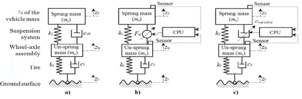
A vehicle's suspension system is a crucial component that shields the frame from road disturbances. This suspension arrangement for a standard car is shownin figure 3.1. The tyres ofa vehicle must stayinconstant contact with the pavement The damper is the most vital component of a suspension system. Absorbing the shock lessens the effects of an unexpected hiccup on the road. Most shock absorbers convert vibrational energy to heat, which is then released into the surrounding area. The viscous damper uses a viscous fluid to turn energy into heat. The hydraulic fluid is heated in hydraulic cylinders. The hot air is released into the atmosphere from air cylinders. As for electromagnetic dampers, the working principle is different, which is" Here, a synchronous machine, induction machine, or DC motor is used to transform vibration energy into electricity, which is then stored in a condenser or battery for later use[1].
Figure 1: Suspension system: (a)Passive (b)Active (c)Semi-Active [2].
Page | 8 Research Publish Journals
International Journal of Mechanical and Industrial Technology ISSN 2348-7593 (Online) Vol. 10, Issue 2, pp: (8-14), Month: October 2022 - March 2023, Available at: www.researchpublish.com
II. CLASSIFICATION OF VEHICLE SUSPENSION SYSTEMS
Dependingontheir degree ofcontrollability, suspensionsystems are divided into three categories: passive, active, and semiactive. Even though each form of suspension system has a unique set of benefits and drawbacks, they all make use of spring and damper units.
A. Passive Suspension System
Passive suspension systems are considered one of the most widelyused systems in the automotive industry due to their high reliability and low cost. They contain a spring with a Passive damper. These systems give stable and specific damping properties. See figure (1a).
A.C. Mitra et al. [3]. This work presents a simulation model based on the Box–Behnken architecture of RSM to analyse ride comfort with correct independent variables. Regression analysis is used to create a prediction model for the response variable, RC, which has a high level of agreement with the simulated model (R2 = 99.74%). The quarter-car model was used in the response analysis with the help of the Matlab/Simulink program.
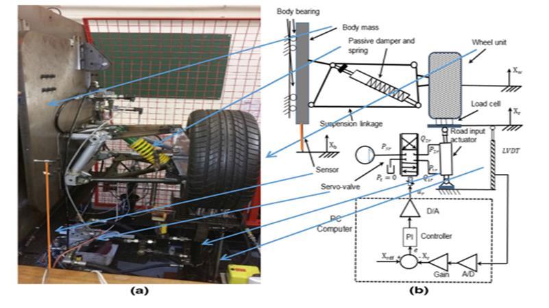
Ali I. H. Al-Zughaibi[4]. Proposed a new nonlinear friction model using a quarter-car passive suspension system. The experimental results and the dynamics system analysis found that there is an exact match between the experimental and analytical results of the nonlinear friction model. The proposed model includes most friction behaviours that appeared in the test results, as it is considered more accurate than the simple friction model. Figure 2 shows a device that was used to gain the practical results of the model.
Figure 2: (a) Photograph of the test rig. (b) Road simulator and schematic of testing equipment [4].
B. Active Suspension System
Active suspension systems are considered one of the best systems that give satisfactory results in damping vibrations. The passive elements in the suspension systems are replaced by a control element that gives strength to the system and is called an actuator. The actuator represents one of the most critical parts of a system and can be classified as an electromagnetic actuator, pneumatic, and hydraulic actuator. Some Literature reviews were given about this system [5].
Amit A. Divekar Bhushan D. Mahajan [6].focused on the development of control algorithms for suspension systems for a quarter car (2DOF) by proposing a control system to reduce the sprung mass displacement and known as Fussy Logic (FLC) control with the use of MATLAB/Simulink. Program to simulate the response results. It compared the proposed control system with the traditional PID, showing that the Fussy PID control device has better results.
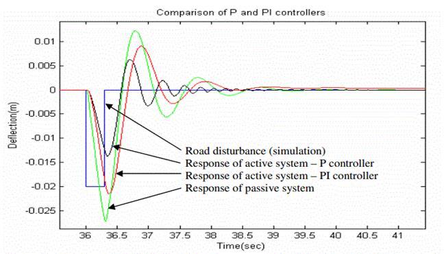
P. Dowds and A. O'Dwyer [7]. The study discusses the modelling of active and passive damping using a quarter-of-avehicle and a full-vehicle model. While compared to the passive suspension system, the active suspension system allows for a much-improved regulator response, As shown in figure (3).The actuator's power usage is the most significant practical difficulty in establishing active suspension. The actuator is typically the controlling component of an active suspension.
Page | 9 Research Publish Journals
International Journal of Mechanical and Industrial Technology ISSN 2348-7593 (Online) Vol. 10, Issue 2, pp: (8-14), Month: October 2022 - March 2023, Available at: www.researchpublish.com
Figure 3: Suspension response for both passive and active system [7].
S.Kilicaslan et al. [8]. The approaches for using ASRE and SDRE techniques to nonlinear control ASS are present in this work, which used a quarter-car suspension model of a Ford Fiesta Mk2. The simulations suggest that the regulation of ASS utilising SDRE and ASRE approaches gives good results. Both approaches' simulation results are compared to the PSS equivalent. Both SDRE and ASRE approaches are effective in meeting performance requirements.
Sellami et al. [9]. The Luenberger observer approach is proposed in this study to design automobile active suspension systems. The keyidea is to employa bond graph approach to diagnose utilising the observer. Where it is displayed an article on the bond graph tool's efficacy in modelling industrial systems based on its structural qualities and ease of use as a graphical tool; provided us with a better representation of the physical system.
C. Semi-Active Suspension System
This study was devoted to semi-active suspension systems, which have been the focus of many researchers as it mixes the advantages of passive and active systems. The semi-active suspension system contains a spring and damper with variable damping characteristics. The most important characteristic of this system is that it turns into a passive system when a malfunction occurs in the control system; this shows high reliability. Some literature reviews of semi-active suspension systems and MR dampers will be present in this part. In order to analyze the dynamic nonlinear behaviour of MR dampers, there are both parametric and non-parametric methods.
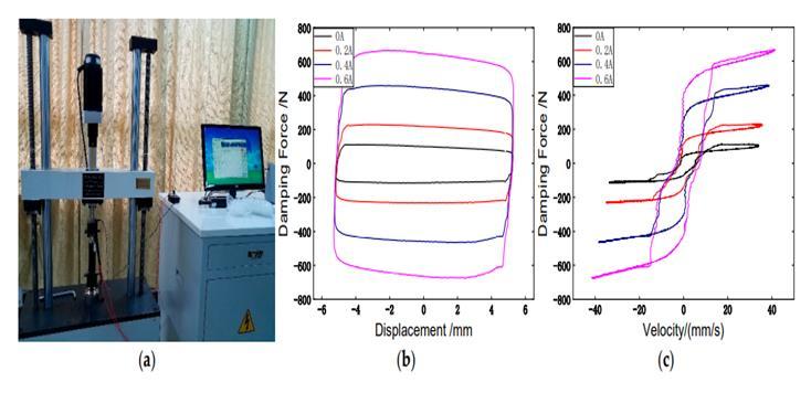
LV Hongzhan et al.[10]. investigated the Bouc-Wen model, the modified Bouc-Wen model, the viscoelastic plastic model, and the hysteresis bi-viscous model. The experiment served as the foundation for the four models. Tests are used to measure the magnetorheological damper's mechanical characteristics. This study showed that, among parametric models, the revised Buoc-wen model had the highest accuracy in explaining the behaviour of MRD, As shown in figure (4). At lower speeds, the prediction error for the damping force is more significant.
Figure 4: The hysterical behavior of the Bouc-wen model with voltage variation: (a) test device (b) force-displacement diagram (c) force-velocity diagram [10].
Hingane, Amit A., et al. [11]. Shows a brief comparison between the semi-active and passive suspension systems. A Bingham model with an MR damper was selected to be tested with the quarter car model (2DOF), and the results were simulated by MATLAB/Simulink program. The results showed a clear improvement in decreasing the acceleration of the spring-mass when using the MR damper.
Page | 10 Research Publish Journals
International Journal of Mechanical and Industrial Technology ISSN 2348-7593 (Online) Vol. 10, Issue 2, pp: (8-14), Month: October 2022 - March 2023, Available at: www.researchpublish.com
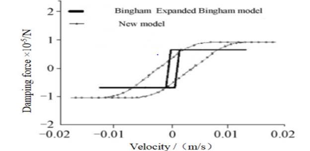
This article [12] examined the dynamical models of the magnetorheological damper. The expanded Bingham model was frequently employed. After that, the simulation was run, and the benefits and drawbacks of the two models were compared (figure (5). Last, a novel dynamical model based on the tangent function was presented. A simulation was used to show the parameters'physical significance. The simulationresults demonstrated that the new model's curve was accurate and smooth. The simulation and research of the magnetorheological damper may be done using it.
Figure 5: The force-velocity diagram for two models [12].
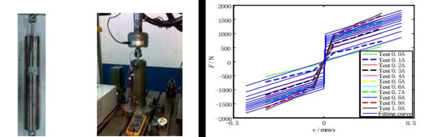
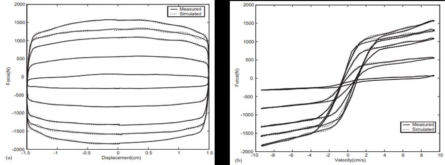
Tu, Fengchen, et al [13].Presented an experimental study of semi-active suspension systems (MRD) with the structural design of the MR damper, which was tested with the experimental results of the damper. The magnetic circuits are welldesigned with the structure for the MR damper. Figure (6a) shows the MR damper that was designed and tested, and on the other hand, figure (6b) shows the test results and their comparison with the relevant result.
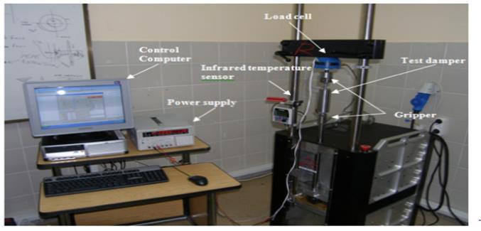
Figure 6: (a) MR damper (b) force-velocity diagram between experimental and analytical results[13]. Şahin et al. [14]. Designed, manufactured and tested the MR damper as shown in figure (7), where eight parametric models were used to explain the behaviour of nonlinear MR dampers. Also, an evaluation was made between three parametric algebraic models and five ordinary differential parametric models. The results showed that the parametric algebraic models better predict the hysterical behaviour of the damper MR.
Figure 7: MR damper tester[14].
Choi, S-B[15]. have compared the measured and predicted dampingstrengthofthe Bingham, Buoc-wenand the polynomial proposed model. The two results show that the Bingham model provides good damping power, but it cannot predict all behaviours of the MR damper. On the other hand, either the Buoc-wen or polynomial model has predicted the nonlinear behaviour of the MR damper well.
Page | 11 Research
Publish Journals
International Journal of Mechanical and Industrial Technology ISSN 2348-7593 (Online) Vol. 10, Issue 2, pp: (8-14), Month: October 2022 - March 2023, Available at: www.researchpublish.com
III. SEMI-ACTIVE VIBRATION CONTROL STRATEGIES
Because the MR damper can only be directly instructed to change the voltage applied to its electromagnet, as a result, in a control system that determines the damper force necessary for the system to respect a reference model, a damper controller is also necessary. For the damper's actual force fa to match the desired force fd, this controller calculates the voltage v that should be supplied. Some control strategies developed and tested for the system controller include H control, fuzzy logic control, flexible neural network control, Skyhook control, linear quadratic Gaussian control, and sliding-mode control robust control [16].
Haiping Du et al. [17]. This study investigated how an MR damper is adapted to a quarter-car model in conjunction with a polynomial model derived from testing data and an appropriately built static output feedback H∞ controller shown in figure (8). The performance of this technique, as tested by numerical simulation, has proven that despite its simplicity, With the polynomial model of the MRD and the static output feedback H∞ controller, equivalent performance to active suspension can be achieved.
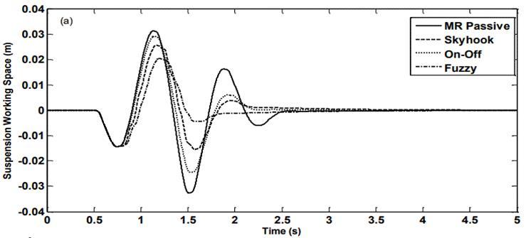
Figure 8: Comparison of practical and analytical results of MRD behavior[17].
Ahmed E. et al. [18]. have studied and simulated semi-active suspension systems using PSO and LQR technology as a system control unit using the Matlab/Simulink environment. By comparing the simulation results, it was concluded in this paper that the PSO technique gives better and more accurate results to improve the performance of the car suspension while reducing vibrations.
K.Dhananjay Rao [19]. Has been used a MATLAB Simulink model to evaluate the effectiveness of a semi-active system foraquarterautomobile model utilisinga PIDcontroller.Thisstudy'sdynamic systemislinear.Essentialvehicle suspension performances like wheel displacement, wheel deflection, suspension travels, body acceleration, and body displacement can be captured using a linear system. The system takes two types of road profiles. According to the results, the proposed PID controller enhances the body and wheel displacement performance.
Alisina S.et al.[20].A theoretical and experimental study using semi-active suspension systems in a quarter-car model with control units was presented. It was used in the Skyhook, fuzzy and On-Off control systems, and the damper control unit was represented by Havsid technology. Figure (9) shows the simulation results for the control techniques with the MR passive suspension system.
Figure 9: The response of the suspension system with the different types of control systems [20].
Page | 12 Research Publish Journals
International Journal of Mechanical and Industrial Technology ISSN 2348-7593 (Online) Vol. 10, Issue 2, pp: (8-14), Month: October 2022 - March 2023, Available at: www.researchpublish.com
IV. CONCLUSION
This chapter reviews some literature specialising in automobile suspension systems, concentrating on semi-active suspension systems that use MR dampers. The main objective of the previous literature is to reach a dynamic model that explains the behaviour of the MR damper with high accuracy in order to be used practically. On the other hand, this field is complicated because of the non-linear behaviour of MR fluids, which are non-Newtonian fluids. From the literature reviewed, it was concluded that the parametric models are the most polarising for researchers because of the theoretical physical behaviour through which the hysterical interpretation of the MR damper is interpreted. On the other hand, the Modify Bouc-wen model is considered one of the most accurate models in numerical analysis.
REFERENCES
[1] Kashem, S., Nagarajah, R. and Ektesabi, M., 2018. Vehicle Suspension System. In Vehicle Suspension Systems and Electromagnetic Dampers (pp. 23-37). Springer, Singapore.
[2] Lajqi, S. and Pehan, S., 2012. Designs and optimizations of active and semi-active non-linear suspension systems for a terrain vehicle. Strojniški vestnik-journal of mechanical engineering, 58(12), pp.732-743.
[3] Mitra, A.C., Patil, M.V. and Banerjee, N., 2015. Optimization of vehicle suspension parameters for ride comfort based on RSM. Journal of The Institution of Engineers (India): Series C, 96(2), pp.165-173.
[4] Al-Zughaibi, A.I., 2018. Experimental and analytical investigations of friction at lubricant bearings in passive suspension systems. Nonlinear Dynamics, 94(2), pp.1227-1242.
[5] Sam, Y.M., Osman, J.H. and Ghani, M.R.A., 2004. A class of proportional-integral sliding mode control with application to active suspension system. Systems & control letters, 51(3-4), pp.217-223.
[6] Divekar, A.A. and Mahajan, B.D., 2016, May. Analytical modeling and self-Tuned fuzzy-PID logic based control for quarter Car Suspension System using simulink. In 2016 IEEE International Conference on Recent Trends in Electronics, Information & Communication Technology (RTEICT) (pp. 267-271). IEEE.
[7] Dowds, P. and O'Dwyer, A., 2005. Modelling and control of a suspension system for vehicle applications.
[8] Kilicaslan, S., 2018. Control of active suspension system considering nonlinear actuator dynamics. Nonlinear dynamics, 91(2), pp.1383-1394.
[9] Sellami, A. and Zanzouri, N., 2017, March. Fault diagnosis of a vehicular active suspension system by Luenberger observer using bond graph approach. In 2017 International Conference on Green Energy Conversion Systems (GECS) (pp. 1-8). IEEE.
[10] Lv, H., Sun, Q. and Zhang, W.J., 2021, September. A Comparative Study of Four Parametric Hysteresis Models for Magnetorheological Dampers. In Actuators (Vol. 10, No. 10, p. 257). MDPI.
[11] Hingane, Amit A., et al. ,2013.Analysis of semi active suspension system with bingham model subjected to random road excitation using MATLAB/Simulink." IOSR Journal of Mechanical and Civil Engineering 3.1 ,pp 01-06.
[12] Zhang, T. and Ren, Z., 2022, April. Research on the arctangent function mechanical model of magneto-rheological damper.In2ndInternationalConferenceonMechanical,Electronics,andElectricaland AutomationControl(METMS 2022) (Vol. 12244, pp. 1063-1069). SPIE.
[13] Tu, F., Yang, Q., He, C. and Wang, L., 2012. Experimental study and design on automobile suspension made of magneto-rheological damper. Energy Procedia, 16, pp.417-425.
[14] Şahin, İ., Engin, T. and Çeşmeci, Ş., 2010. Comparison of some existing parametric models for magnetorheological fluid dampers. Smart materials and structures, 19(3), p.035012.
[15] Choi, S., Lee, S., & Park, Y. 2001. A hysteresis model for the field-dependent damping force of a magnetorheological damper. Journal of Sound and Vibration, vol.245, pp375-383.
[16] Metered, H.,2012. Applicationofnonparametric magnetorheological damper model invehicle semi-active suspension system. SAE International Journal of Passenger Cars-Mechanical Systems, 5(2012-01-0977), pp.715-726.
Page | 13 Research Publish Journals
International Journal of Mechanical and Industrial Technology ISSN 2348-7593 (Online) Vol. 10, Issue 2, pp: (8-14), Month: October 2022 - March 2023, Available at: www.researchpublish.com
[17] Du,H.,Sze,K.Y.andLam,J.,2005.Semi-activeH∞control ofvehiclesuspensionwithmagneto-rheologicaldampers. Journal of sound and vibration, 283(3-5), pp.981-996.
[18] Elsawaf, A., Metered, H. and Abdelhamid, A., 2019. Minimizing Power Consumption of Fully Active Vehicle Suspension System Using Combined Multi-Objective Particle Swarm Optimization (No. 2019-01-5077). SAE Technical Paper.
[19] Rao, K.D., 2014. Modeling, simulation and control of semi active suspension system for automobiles under matlab simulink using pid controller. IFAC Proceedings Volumes, 47(1), pp.827-831.
[20] Shojaei, A., Metered, H., Shojaei, S. and Olutunde Oyadiji, S., 2013. Theoretical and Experimental Investigation of Magneto-Rheological Damper based Semi-Active Suspension Systems. International Journal of Vehicle Structures & Systems (IJVSS), 5.
Page | 14 Research Publish
Journals