
Vol. 10, Issue 4, pp: (23-32), Month: October - December 2022, Available at: www.researchpublish.com
Design of Lighting System and Watering Automation Based Internet of Things with Message Queuing Telemetry Transport Protocol and Framework Flutter
Syaifur Rohman1 , Bambang Sujanarko2, Bambang Sri Kaloko3
1,2,3Department of Electrical Engineering, Jember University, Jember, Indonesia
DOI: https://doi.org/10.5281/zenodo.7347542
Published Date: 22-November-2022
Abstract: The management of electricity consumption for lamps and water tanks generally relies on a kWh meter, so it is still not effective because it can only monitor and limit electricity usage, not being able to turn off pumps and unused lights. These problems can be overcome with the Internet of Things, which is able to connect equipment through the internet network. The process requires a communication protocol system, which is efficient in terms of bandwidth, latency, and power consumption. The communication protocol model used in this study is Message Queuing Telemetry Transport, considering that this protocol can connect to slow networks. The test results show that the Message Queuing Telemetry Transport (MQTT) application has a better performance on the lighting and watering automation system, which is implemented on a mobile application using the Flutter framework to receive and display high-load garden light control, waterpump control and underground reservoir water level monitoring. The calibration results show that the HYSRF05 sensor can work well in the range of 50-150 cm, with a maximum relative error of 0.36%. The smallest distance change that can be detected by the sensor is 0.04 cm with a maximum relative error of 0.05%. With the magnitude of the error obtained, it can be said that the sensor is suitable for use as a water level detector in an underground reservoir water level monitoring system. The power consumption for lighting and water pumps shows that the design of this system has an impact on power savings of 118.03 kWh. With the Flutter framework, a Mobile Application was built to manage and handle underground reservoir water level monitoring system data, so that users can set conditions to notify users about water level thresholds, use of lighting devices and water pumps through aMobile Application that is equipped with a Notification feature thatis integrated in real-time.
Keywords: Internet Of Things (IOT), MQTT, Lighting and Waterpump Control, Underground Water Reservoir Monitoring, Flutter, Mobile Apps
I. INTRODUCTION
Difficulties in the process of controlling electrical equipment for office building operators are due to the large area of the building associated with the process of controlling the switch from electrical devices in buildings which are generally still manual, so it takes a long time to activate electronic devices inside the building. In addition, due to the decline in human mobility during the pandemic for work and other activities, this has resulted in an increasing demand for remote control and monitoring technology for office buildings such as monitoring and controlling electronic devices [2]. Management of electrical energy consumption in usage is not enough just to use a kWh meter, because using a kWh meter is only in charge of monitoring and limiting overall electricity use. Therefore, awareness is needed to really save in the use of electrical energy. Electrical energy management can be done by looking at the consumption of electrical energy and then managing unused electronic equipment so that the cost of using electrical energy does not increase.
International Journal of Electrical and Electronics Research ISSN 2348-6988 (online)
Page | 23 Research Publish Journals
Ardianto
International Journal of Electrical and Electronics Research ISSN 2348-6988 (online)
Vol. 10, Issue 4, pp: (23-32), Month: October - December 2022, Available at: www.researchpublish.com
To solve the problem, there is a proposition for a smart building solution that enables remote monitoring and control of devices in the office building sector to identify manual or automated use of devices and control devices within the building. Smart home as an environment equipped with advanced intelligence technology that manipulates and responds according to the wishes of the occupants of the house [3]. The Internet of things (IoT) is becoming a technology consisting of a large number of different devices with diverse processing, sensing, driving, and communicating capabilities. Therefore, various new automation controls in the IoT field are being developed in many variations to make it easier for residents in the IoT environment. There are many data communication controls used in IoT technology such as: HTTP (HyperText Transfer Protocol), MQTT (Message Queieng Telemetry Transport) and CoAp (Constrained Application Protocol) [4].
One of the machine to machine (M2M) communication protocols that will be discussed in this study is MQTT. MQTT is a TCP-based protocol developed by IBM [5] with a publish/subscribe interaction pattern, which consists of one broker server and two types of clients called Publisher and Subscriber. Brokers act as intermediaries for messages sent between Publisher and Subscriber clients with special topics [6].
So, this paper presents the implementation of Design Lighting and Watering Automation System with Message Queuing Telemetry Transport Protocol and Framework Flutter With the MQTT data communication protocol for IoT Applications in an intelligent integration based environment that supports an economical monitoring system using an ESP8266 NodeMCU connected to an ultrasonic sensor and a 4 channel switching driver connected to each other on the Mobile Application. ESP8266 collects data from sensors and publishes it to the MQTT Broker and also we implement water level monitoring and garden light control using a Mobile App with Flutter framework which integrates with MQTT and retrieves sensor data to display it in the form of animated, text and graphical user interfaces.
II. METHODOLOGY
A. Purpose and Contribution
The main objective of this research is to design and implement smartbuilding solutions at PT. Graha Sarana Duta Jember building facility uses ESP8266 with the MQTT data communication protocol, for monitoring the height of underground water reservoirs and remotely controlling the garden lighting system. With the aim of streamlining operational expenses, accelerating and facilitating building operators in monitoring the operational activities of building infrastructure.
B. System Architecture
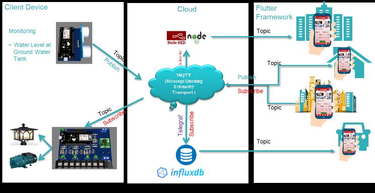
Figure 1. System Architecture
Figure 1 shows the proposed system architecture for the Nodemcu ESP8266 smartbuilding with MQTT and a custom application. The smartbuilding automation application runs on the Broker HiveMQ Cloud data communication protocol as a gateway to control various devices embedded with ultrasonic sensors HYSRF05 and trigger relays and contactors in real time.
Page | 24 Research Publish Journals
International Journal of Electrical and Electronics Research ISSN 2348-6988 (online)
Vol. 10, Issue 4, pp: (23-32), Month: October - December 2022, Available at: www.researchpublish.com
C. MQTT Messasging Protocols
MQTT (Message Queue Telemetry Transport) is a publish/subscribe based communication protocol. The MQTT client has a very small memory size, is light and efficient, requires minimal resources so that it can be used on even small microcontrollers. MQTT message headers are small, optimizing network bandwidth. The data sent is a minimum size of 1 kb. MQTT two-way communication enables device-to-cloud and cloud-to-device messaging. It can support less reliable networks, so this very useful advantage is useful even in slow network conditions. MQTT security makes it easy to encrypt messages using TLS and authenticate clients using modern authentication protocols, such as OAuth. (https://mqtt.org/).
Start
IP,Port,Username,Broker, Password, SSID Paswword,Initialization
Is Connect?
Connect Broker MQTT
Is Connect?
Receive Sensor data
Publish Sensor Data to Broker MQTT End
Figure 2. Flowchart MQTT Publisher
Explanation of Figure 2 is the initialization of IP, Port, Username and Password of MQTT Broker on ESP8266. Initialize SSID, WLAN Password used. Next, the WLAN and MQTT Broker connection authentication process based on the initialized data. Data is received by ESP8266 and then published to MQTT Broker. The process of publishing data will repeat itself every time with a delay in the program.
Start
IP,Port,Username,Broker, Password, SSID Paswword,Initialization
Is Connect?
Connect MQTT Is Connect?
Subscribe Sensor Data from MQTT
Show Sensor data to Mobile APP
End
Figure 3. Flowchart MQTT Subscriber
Explanation of Figure 3 is the initialization of the IP, Port, Username and Password of the MQTT Broker on the ESP8266 Pi. Initialize SSID, WLAN Password used. Next, the WLAN and MQTT Broker connection authentication process based on the initialized data. Subscription data from MQTT Broker and then received to the Mobile application. Subscribing the data process will repeat at any time with a program delay.


Page | 25
Research Publish Journals
D. Driver Switching for Lighting and Water Pump Control

Figure 4. Driver Switching for Lighting and Water Pump Control
Figure 4 shows the relay driver design for lighting and water pump control integrated with the NODEMCU ESP8266 controller withanapplicationinterface schematic created using flutter. The RelayDriver functions as a breaker or connector for the flow of electric current which is controlled by providing a certain voltage and current to the coil. In this circuit, a DC relayis used witha coil voltage of12 Volt DC and a current treated ofabout 20 – 30 milli Ampere. Therefore, in general we cannot directly connect the NodeMCU output to the relay because the current is not large enough. Therefore, it is necessary to use a driver as a current amplifier which is usually a transistor.
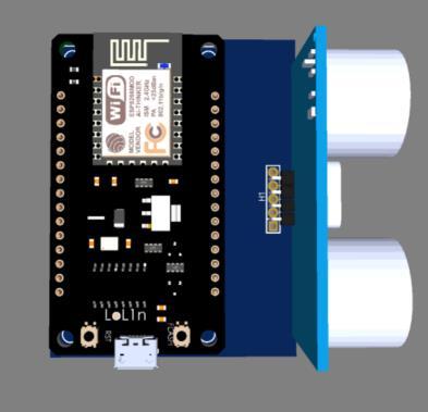


Figure 5. Self Holding Contactor
Figure 5 is a self holding contactor circuit with NO and NC relays switches. This self holding contactor holding circuit is commonlyused in motor control, motor starter circuits such as DOLstarters, star delta starters, but we applythis application to control lighting with higher loads using 3 phase magnetic contactors. The main purpose of this self-holding circuit is to keep the magnetic contactor ON even after removing the relay from the NO relay.

E. Shield HYSRF05
Figure 6. Shield HYSR05
Page | 26 Research Publish Journals
International Journal of Electrical and Electronics Research ISSN 2348-6988 (online) Vol. 10, Issue 4, pp: (23-32), Month: October - December 2022, Available at: www.researchpublish.com
International Journal of Electrical and Electronics Research ISSN 2348-6988 (online)
Vol. 10, Issue 4, pp: (23-32), Month: October - December 2022, Available at: www.researchpublish.com
Figure 6 shows the design of the HY-SR 05 is an ultrasonic transmitter/receiver used to measure distances with a precision of ~0.3cm. The HY-SRF05 sends a 40 KHz wave signal that bounces off objects in front of the sensor. This signal is then read back bythe sensor and the duration of the received signal is reflected on the ECHO pin. Characteristics Supply voltage: 4.5V to 5.5V (VCC) Use the elapsed time in the following formula to find the distance in cm using this equation in (1). d = v * �� 2 () where
• d is distance.
• v is speed of sound 0.034 cms/us.
• t is total measured time 588 us
The HY SRF05 sensor used during calibration is 1 piece, where the sensor is placed at a distance from the surface of the lid. The error is calculated using equation (2):
Error(%) = 100% x |���� ����| ���� (2)
Where, JS is the sensor readingdistance, and JA is the actual distance. Inthis case the actual distance is the distance obtained through manual measurement using a ruler
F. Power Source Characteristic
PLN (Perusahaan Listrik Negara) is electrical energy company in Indonesia using alternating current or alternating current (AC) electricity generated from an AC generator. Voltage and alternating current are usually expressed in terms of RMS (Root Mean Square) values. The RMS itself is usually known as the mean squared whose statistical measurement of magnitude has an arbitrary magnitude. Calculating the change in voltage and current in a sine manner can be calculated by equation (3):
Vrms = A* 1 √2 (3) where
• Vrms is root mean square Voltage.
• A is the amplitude of the signal being sampled.
Electrical power is the rate of transmission of electrical energy in an electric circuit. Electrical power consists of, active power using equation (4), reactive power using equation (5), and apparent power using equation (6):
P = V x I x cos phi (4)
Q = V x I x sin phi (5)
S = V x I (6) where
• V is voltage (Volt).
• I is current (Ampere)
• P(Active Power), Q(Reactive Power), S(Apparent Power)
• Cos phi, Sin phi is power factor.
G. Software Design Flutter Framework Adoption Scheme
Figure 7 shows the flowchart and user interface application of the flutter schema adoption that uses MQTT data communication which allows dashboard visualization and output control in publish and subscribe sensor data values to application dashboards, Influxdb databases, and Notifications on Mobile Applications by combining API (Application) programs. Programming Interface) NodeJs with Node-Red.
Page | 27 Research Publish Journals
International Journal of Electrical and Electronics Research ISSN 2348-6988 (online)
Vol. 10, Issue 4, pp: (23-32), Month: October - December 2022, Available at: www.researchpublish.com
Figure 7. Flowchart of Mobile Apps using the Flutter Framework Adoption Scheme
III. RESULT
A. Data Collection from HY-SRF05 on Ground Water Tank
Data retrieval using a scale of 1:100 from the actual situation (water level status of the Ground Water Tank). Data retrieval is done by placing the sensor on the surface of the underground water reservoir cover then the distance of the object from the sensor is reduced according to the maximum limit for underground water storage. The data taken is 20 times sensor readings with a time lag of each reading for 3 seconds.
Table 1. Average Actual Distance with Ultrasonic Sensor Reading Distance HYSRF05
Actual Distance (cm) Sensor Reading Distance (cm) Relatif Error (%) 50 49,82 0,36 75 74,96 0,05 100 99,87 0,17 125 125,12 0,09 150 149,91 0,05
Figure 8. Dimensions of GWT (Ground Water Tank)


B. Waterlevel Monitoring Dashboard
Regulate the availability of water in the ground water tank reservoir for monitoring water in the ground water tank with a smartphone connected to the internet with the MQTT protocol. With the monitoring dashboard on the Mobile application programmed using the flutter framework, it allows users to manage and optimize water level equipment and control water pump using IoT (Internet of things) especially using the MQTT protocol.
Page | 28 Research Publish Journals
International Journal of Electrical and Electronics Research ISSN 2348-6988 (online)
Vol. 10, Issue 4, pp: (23-32), Month: October - December 2022, Available at: www.researchpublish.com
Figure 9. Visualization of Flutter Interface Application with MQTT Waterlevel Monitoring Dashboard on Mobile Apps


Figure 9 shows the designofthe Mobile dashboard applicationfor visualizationofthe reservoir water level usingthe flutter framework which is connected to the mqtt and influxdb databases and is integrated with notifications programmed through Node red and the Nodejs API.
C. Lighting Control Dashboard
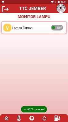
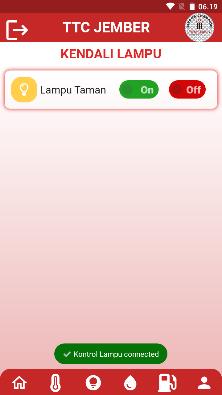
Figure 10. Visualization of the Lighting Control Interface Flutter Application with MQTT
Figure 10 shows the implementation of the lighting control dashboard mobile app and conducted experiments to test the reliability of the system and to estimate response times from both the app and web accounts. The results showed that the lamp control system was reliable and more convenient, in controlling the switching operation of the Mobile application designed and programmed with the flutter framework, the system only needed a few seconds to control the operation.
D. Direct Notify from Apps

Page | 29 Research Publish
Journals
Figure 11. Visualization of the Application Notification interface with the Flutter Framework
International Journal of Electrical and Electronics Research ISSN 2348-6988 (online)
Vol. 10, Issue 4, pp: (23-32), Month: October - December 2022, Available at: www.researchpublish.com
We simulate notifications with the upper and lower limits of the water level. In our setting the water level is less than 93%, we mark it as a water shortage condition. For water levels above 98%, we mark it as full. Figure 11 is a graph on the dashboard showing when the water level is less than 93%. It detects that the water level is less than 93% at 1:21 pm and automaticallyturns the water pump on. And Figure 10. shows that the water level is over 98% at 2:31p.m. and automatically turns the water pump off.
Figure 12. Node Red Flow Visualization for Sending Notifications on Mobile Apps with NodeJs API
Figure 12 Node-red is an MQTT client that subscribes to MQTT Broker on topics published by the device. Researchers designed a flow to manage and manage data from device sensors, the http request node (API Notify OneSignal) is a node that connects to the notification service on Mobile apps via the web API. Thus, users who are registered with Mobile Apps, Node-Red Notification service and NodeJs API will send notification messages to users at 13:21 and notification messages at 14:31 as shown in Figure 11.
E. Database InfluxDB
The outermost construct of InfluxDB is called organization, which is a dashboard consisting of buckets, which are named locations where all time series data is stored. All buckets have a time duration, called a retention period, during which each data point remains, and when a point has a timestamp that is longer than the retention period, it is deleted by InfluxDB to reduce overall disk usage. Measures are conceptually similar to tables in a relational database, and are named buckets for tags, fields, and timestamps.

Figure 13. InfluxDB Database
Figure 13 shows a bucket and dashboard named “Water Level Ground Water Tank”, which contains monitoring measurements for the height of the stored underground water reservoir (GWT).

F. Power Consumption
Table 2. Data Load Panel Device Panel
Based on the amount of load on each device, we get a calculation of the power consumption of each device by comparing power consumption based on the use of water pump and lighting equipment loads before and after the design of the Internet of Things-based Lighting and Watering Automation System With the PLN line to line voltage input 380V and line to netral input 230V with cos 0,972 the power consumption per day is obtained through equation (4):
Page | 30 Research Publish
Journals
LOAD
Average
R S T
3,4 3,8 0,6 4,2
(Ampere)
(Ampere)
Lighting
A Water Pump 0 0 4,9
International Journal of Electrical and Electronics Research ISSN 2348-6988 (online)
Vol. 10, Issue 4, pp: (23-32), Month: October - December 2022, Available at: www.researchpublish.com
Table 3. Power Consumption Data Based on Load Usage
Load Type Daily Usage
Power (kWh) Before After Before After
Lighting 11 hour 10 hour 19,2 17,4 Water Pump 6 hour 4 hour 6,6 4,4
Load Type
Monthly Power Usage (kWh) August 2022 September 2022
Lighting 575,44 523,13 Water Pump 197,17 131,45
Monthly Power Consumption (kWh)
0 200 400 600 800 Aug-22 Sep-22
Penerangan Pompa
Figure 14.
Monthly Power Consumption Chart
The power consumption of lighting and water pump loads in Figure 14 shows the power consumption before and after the design of this system which is compared and calculated in the period from August 2022 to September 2022 has an impact on power savings of 118.03 kWh.
IV. CONCLUSION
We present low-cost lighting and watering automation system design. The design of Lighting and Watering automation system with Message Queuing Telemetry Transport Protocol and Flutter Framework was created using a NodeMCU ESP8266 board device connected to a HYSRF05 sensor to detect the water level of underground reservoirs and a Switching Driver to control Lighting and Water Pump for irrigating underground water reservoir. In the calibration carried out for the ultrasonic sensor, it can be concluded that the sensor works well from a distance of 50 cm to 150 cm with a maximum relative error of 0.36% with a minimum change detected by the sensor of 0.04 cm with a maximum relative error of 0.05%. Power consumption on lighting and water pump loads after the system design has an impact on power savings of 118.03 kWh. Lighting control and underground water tank automation are implemented in the Mobile application using the Flutter framework to receive and display lighting control data with large power loads and underground water level monitoring data or GWT (Ground Water Tank). With the Flutter framework, we designed the flow to manage and handle water level monitoring system data in underground reservoirs or (Ground Water Tank) and garden lighting control, so that users can set conditions to notify users about water level thresholds through the Mobile Notify service which integrated in real-time via Node-RED, NodeJS API, and devices communicating via MQTT Broker in a publish and subscribe model.
REFERENCES
[1] Mtshali, Progress, and Freedom Khubisa. ”A smart home appliance control system for physically disabled people.” 2019 Conference on Information Communications Technology and Society (ICTAS). IEEE, 2019.
[2] Waleed, Jumana, Areej M. Abduldaim, Taha Mohammed Hasan, and Qutaiba Salih Mohaisin. ”Smart home as a new trend, a simplicity led to revolution.” In 2018 1st International Scientific Conference of Engineering Sciences-3rd Scientific Conference of Engineering Science (ISCES), pp. 30-33. IEEE, 2018.
[3] P.Machesoae,T.D.Mandab,S.Chisalec,N.Dzupired ,J.Mlathoa and D.Mukanyiligirae ”Design of ESP8266 Smart Home Using MQTT and Node-RED” International Conference on Artificial Intelligence and Smart Systems (ICAIS2021). IEEE; 2021
Page | 31 Research Publish Journals
International Journal of Electrical and Electronics Research ISSN 2348-6988 (online) Vol. 10, Issue 4, pp: (23-32), Month: October - December 2022, Available at: www.researchpublish.com
[4] Emmanuel I. Nwankwo, Elizabeth N. Onwuka, Michael David and Zubair Suleiman. ”Hybrid MQTT-COAP Protocol for Data Communication in Internet of Things” Institutional Based Research Intervention (IBRI). IEEE; 2021
[5] A. Rizzardi, S. Sicari, D. Miorandi, and A. Coen-Porisini, “AUPS: An Open Source AUthenticated Publish/Subscribe system for the Internet of Things,” Inf. Syst., vol. 62, pp. 29–41, 2016
[6] R. A. Light, “Mosquitto : server and client implementation of the MQTT protocol,” no. May, pp. 10–11, 2017
[7] Paul Macheso, Tiwonge D. Manda, Sylvester Chisalec, Nelson Dzupired , Justice Mlatho and Didacienne Mukanyiligira. ” Design of ESP8266 Smart Home Using MQTT and Node-RED” IEEE Proceedings of the International Conference on Artificial Intelligence and Smart Systems (ICAIS), 2021
[8] Mohammed Abduljabbar Hayil Hayil, “Home Automation System And Methods(Control System in Lighting and Devices) in Fuel Supply Station,” in IEEE Explore Auckland University of Technology , 2020.
[9] K.Jaikumar, T.Brinda, T.K Deepalakshmi, S. Gomathi , “IOT Assisted MQTT for Segregation and Monitoring of Waste for Smart Cities ,” in IEEE 6th International Conference on Advanced Computing & Communication Systems (ICACCS), 2020
Page | 32 Research Publish
Journals