International Journal of Civil and Structural Engineering Research ISSN 2348-7607 (Online) Vol. 6, Issue 2, pp: (99-108), Month: October 2018 - March 2019, Available at: www.researchpublish.com
ANALYSIS ON THE THERMAL TRANSMITTANCE/ CONDUCTANCE OF BUILDING ELEMENTS (ROOF, WALL AND FLOOR) BASED ON THE DIFFERENT BUILDING MATERIALS USED IN FAMAGUSTA
1Francis Akankali, 2Halil Zafer Alibaba
1M.Arch Department of Architecture, Eastern Mediterranean University, Faculty of Architecture, Gazimagusa, T.R. of Northern Cyprus, Turkey.
2Associate Professor, Dr. Department of Architecture, Eastern Mediterranean University, Faculty of Architecture, Gazimagusa, T.R. of Northern Cyprus, Turkey
Email:akankaliemeke@gmail.com, Email:halil.alibaba@gmail.com
Abstract: Buildings are generally made of different elements, and to create a shelter or complete building, the three basic elements that make up the shelter space or building. They are the roof element, the wall element and the floor element. These different elements directly affect the thermal comfort of the space which they form and as such the materials used in creating these elements play a main role in the thermal comfort of this space. Therefore this study will be dealing with the calculation of the thermal resistance and conductance of the elements based on the type of materials used.
Keywords: Thermal Conductance- U. Value, thermal Resistance – R value, Building Element, Roof Element, Wall Element, Floor element.
1. INTRODUCTION
Thermal comfort is a very important factor in terms of the general well-being of humans and were they live and although most times the environment cannot be controlled as it comes from mother nature, there spaces in which we live in and create as shelter can help provide thermal comfort relatively shielding humans from the sometimes harsh conditions given by the environment.
Although, with the further advancement of technology especially in building technology, thermal comfort can be reached through the use of mechanical and electrical means like the use of Air conditioners, Radiators, Fans and so on. These all help in regulating the temperature to the appropriate value that we might need at that particular time and space.
But these can also go as far as to regulate the temperature for a particular time period and its left for the controlled space to be able to conduct or resist these temperature to be able to retain the thermal comfort and this is done by the elements that constitute the space which are the walls, roof and floor elements and furthermore, the materials that make them up. Thermal resistance of existing building envelopes is an important factor in defining the total energy consumption of heating and cooling systems and achieving optimal thermal comfort for occupants. The R-value is a measure of how well an envelope resists the heat-flow. With higher R-values, the insulating effectiveness is greater. The R-value or conductance depends on the material type, thickness, and density of each layer. The heat transfer by conduction, radiation
International Journal of Civil and Structural Engineering Research ISSN 2348-7607 (Online)
Vol. 6, Issue 2, pp: (99-108), Month: October 2018 - March 2019, Available at: www.researchpublish.com
and convection can be reduced through appropriate construction techniques and choice of materials. In some conditions, the real R-value of building envelope components does not always agree for various reasons with the value declared by manufactures or estimated in the design phase. It is important to measure and analyze the building envelope R-value in situ.
This study aims to study the thermal resistance and transmittance of the elements that constitute a typical building in Famagusta and thereby create a table and value for the construction materials that are generally used in the various elements of the particular building. And this will give an idea of the thermal capacity of the given building. Or elements as it is needed. Thermal transmittance and resistance are what constitute the overall thermal conductance of the elements and therefore the building in general.
Nomenclatures that will be encountered during the research and literature review include;
Rn test wall thermal resistance calculated after n measurements [m2 K/W]
tsw surface temperature on the test wall warm side [◦C, K]
tsc surface temperature on the test wall cold side [◦C, K]
q heat-flow rate through the test wall [W/m2]
R10 R-value calculated with a tair ≈10 ◦C [m2 K/W]
R7 R-value calculated with a tair ≈7 ◦C [m2 K/W]
s thickness of a layer of the test wall [m]
S area of the wall [m2]
RD R-value calculated through the destructive method [m2 K/W]
Q transmission heat loss through a wall [W]
q Transmission heat loss through a wall per unit area and per unit difference of temperature [W/m2 K]
hi internal surface heat transfer coefficient [W/m2 K]
he external surface heat transfer coefficient [W/m2 K]
tint internal set point temperature [◦C, K]
text external temperature [◦C, K]
2. LITERATURE REVIEW
Many existing structures in Cyprus have poor thermal execution.
Florides et al.4 reenacted a normal house with different development designs that speak to present day Cypriot houses, and found that without warming or cooling indoor temperatures gone from 10 to 20C in winter and up to 30– 50C in summer.
An overview by Lapithis et al.5 found that most tenants of present day houses in Cyprus complained of lacking comfort; 80% of members feeling chilly in winter and 87% inclination hot in summer. Thermal construction of structures in Cyprus can be enhanced by changes to building geometry also, developments. Rabah6 expressed in North Cyprus, modelers and architects have not considered the neighborhood atmosphere amid the arranging stage and this causes poor thermal solace. In light of Mahoney investigation, he prescribed that structures ought to have a minimized yard plan with long hub arranged east– west, little opening sizes (up to 20% of divider surface), and overwhelming dividers, rooftops and floors with a period slack of 8 hours. Ozdeniz and Hancer7 tried 14 distinctive rooftop developments on a test room in Cyprus. They discovered that the best performing rooftops for the summer period were a slanted timber rooftop which remained on a solid chunk with ventilated upper room, and a level rooftop which had thermal protection towards the inward layer. Kalogirou et al.8 reenacted a four-zone Cyprus working with a thermal mass (thick concrete divider) in the south veneer. The ideal thickness of the thermal mass was observed to be 25 cm, which gave a 47% decrease in warming stack and a 4.5% expansion in cooling load when contrasted and a similar building having no included thermal mass. As of not long ago, there was no enactment with respect to vitality productivity of structures in any piece of Cyprus, and there is still
International Journal of Civil and Structural Engineering Research ISSN 2348-7607 (Online) Vol. 6, Issue 2, pp: (99-108), Month: October 2018 - March 2019, Available at: www.researchpublish.com
none in North Cyprus. Individuals are not commonly mindful of vitality preservation in structures, thusly this isn't a need for them. In this manner, there is an incredible requirement for low-vitality building examines in Cyprus.
A lot of calculations and experiments have already been carried out in various places in the world concerning thermal properties of different materials and not just with buildings but also with other elements.
Thermal Resistance; The flow of heat going in and out of a structure is highly dependent on the temperature difference going on the opposite sides, the rate of conductivity of the materials used in line with the width of the given material. Definitely, the differences in temperature is also a factor to be considered externally. This width and conductivity are characteristics of the given materials. A bigger width translates into less thickness means less heat flow and so does a lower conductivity. Together these parameters form the thermal resistance of the construction. The thermal resistance is proportional to the thickness of a layer of the construction and inversely proportional to its conductivity. A construction layer with a high thermal resistance (e.g. rock wool), is a good insulator; one with a low thermal resistance (e.g. concrete) is a bad insulator.
k = represents the conductivity of the material (W/mK)
For a composite building component made up of various layers of various materials, its aggregate resistance is given as:
Rt = Rso + ∑Rn + Rsi where the resistance of the nth layer is:
Rn = ln/kn
Rt = the aggregate by and large resistance of the component (m²K/W), Rn = the resistance of the nth material inside a composite component (m²K/W), Rso and Rsi are the outside and inside surface resistances individually (m²K/W)
ln = the thickness of the nth material in a composite component (m), and kn = is the conductivity in of the nth material in a composite component (W/mK).
Luckily, enough is thought about different materials to empower the figuring of a general thermal character for most normal settled measurement building frameworks with the goal that a general resistance (or conductance) can be determined. Figures can be determined for single coated and twofold coated windows, solid piece floors, suspended wooden floors, dividers, etc. These qualities are normally composed as either a R-Value (for protections) or a U-Value for different components.
The R-Value Resistance is generally given as a "R" esteem which is the resistance of one square meter of the material subject to a one degree temperature distinction. Hence a R estimation of a regular fiber glass bat might be given as R = 2.4, with the suggestion that it has the units m²K/Watt. This implies on the off chance that one takes the region of protection in square meters duplicated by the temperature distinction in degrees Kelvin and isolated by 2.4, one gets the warmth stream in Watts.
For instance, 100 square meters of R = 2.4 protection, presented to a 20 degree K contrast, will go around 833 Watts. Indeed, the warmth misfortune would be required to be somewhat from this in light of the fact that there is an extra resistance in getting the vitality from within air to the divider surface, and from the outside divider surface to the outside air. Additionally, the warmth exchange outwardly surface may differ with wind speed.
Transmittance or U-Value; In actuality, situations in all the building segments, warm exchange happens through all the three modes. For instance, in the outline beneath, the divider gets warm through convection from the encompassing air, through conduction the warmth gets transmitted up to the inward surface where again through convective warmth exchange due to inside room air, and warmth goes into the building. Using the idea of warm opposition, the general warmth exchange can be found using:
Qc = (T outside – T inside)/{(1/hoA) + (l/kA) + (1/hiA)}
International Journal of Civil and Structural Engineering Research ISSN 2348-7607 (Online) Vol. 6, Issue 2, pp: (99-108), Month: October 2018 - March 2019, Available at: www.researchpublish.com
The above equation can be written in an improved frame as:
Qc = U * A * (T outside – T inside) Where, U = 1/{(1/ho) + (l/k) + (1/hi)}
The term 'U' speaks to by and large warm conductance from the outside to inside covering all methods of warmth exchange. From the above equation, 'U-value' can be characterized as the rate of warmth stream over unit region of any building segment through unit generally speaking temperature contrast between the two sides of the segment.
The U-Value is an imperative idea in building structure. It speaks to the aerial transmittance of a component. This alludes to how well a component conducts warm from one side to the next, which makes it the equal of its warm obstruction. Thus, on the off chance that we calculate the warm obstruction of a component, we can essentially reverse it to acquire the U-Value
U = 1/Rt
U = 1/(Rso + ∑Rn + Rsi)
The U-Value is a property of a material. Thus, its units are Watts per meter squared Kelvin (W/m² K). This implies, if a divider material had a U-Value of 1 W/m² K, for each level of temperature distinction between within and outside surface, 1 Watt of warmth vitality would course through each meter squared of its surface.
Calculation of U – value
Calculate the U-value for the 220 m block wll with 16 mm mortar within face. Assume ordinary exposure.
For brick, k=0.84W m-1K-1; for mortar k= 0.5 W m-1K-1
Inward obstruction, Rsi = 0.123 m2 K W - 1
Mortar opposition = l/k = 0.016/0.5 = 0.032 m2 K W - 1 Block opposition, Rso=0.055m2K W-1
Subsequently,
Add up to opposition = 0.123 + 0.032 + 0.262.+ 0.055 = 0.472 m2K W-1
Thusly, U = 1/∑R = 2.12 W m - 2K-1
Thermal conductivity is a material property. It won't contrast with the elements of a material, however it is reliant on the temperature, the thickness and the dampness substance of the material. The thermal conductivity of a material relies upon its temperature, thickness and dampness content. The thermal conductivity regularly found in tables is the esteem substantial for ordinary room temperature. This esteem won't vary much somewhere in the range of 273 and 343 K (0 70° C). At the point when high temperatures are included, in broilers for example, the impact of temperature must be considered. By and large light materials are preferable protectors over substantial materials, since light materials regularly contain air walled in areas. Dry still air has a low conductivity. A layer of air won't generally be a decent separator however, on the grounds that warm is effortlessly exchanged by radiation and convection.
At the point when a material, for example protecting material, winds up wet, the air fenced in areas load up with water and, in light of the fact that water is a superior conductor than air, the conductivity of the material increments. That is the reason it is essential to introduce protection materials when they are dry and take care that they stay dry.
Conductivity (k) is a material property and means its capacity to lead warm through its inward structure. Conductance then again is a protest property and relies upon the two its material and thickness. Conductance breaks even with conductivity increased by thickness, in units of W/m²K. As conductivity is the complementary of resistivity, the aggregate opposition of a material can consequently be given as its thickness separated by aggregate conductivity.
Research Publish Journals
International Journal of Civil and Structural Engineering Research ISSN 2348-7607 (Online) Vol. 6, Issue 2, pp: (99-108), Month: October 2018 - March 2019, Available at: www.researchpublish.com
Table showing the thermal conductivity of different building materials according to the specific mass. (Clear, n.d.)
Group Material
Specific mass (kg/m3) Thermal conductivity (W/mK) Dry Wet
Metal Aluminum 2800 204 204
Copper 9000 372 372 Lead 12250 35 35 Steel, Iron 7800 52 52 Zinc 7200 110 110
Natural stone Basalt, Granite 3000 3.5 3.5 Bluestone, Marble 2700 2.5 2.5 Sandstone 2600 1.6 1.6
Masonry Brick 1600-1900 0.6-0.7 0.9-1.2 Sand-lime brick 1900 0.9 1.4 1000-1400 0.5-0.7
Concrete Gravel concrete 2300-2500 2.0 2.0 Light concrete 1600-1900 0.7-0.9 1.2-1.4 1000-1300 0.35-0.5 0.5-0.8 300-700 0.12-0.23
Pumice powder concrete 1000-1400 0.35-0.5 0.5-0.95 700-1000 0.23-0.35 Isolation concrete 300-700 0.12-0.23 Cellular concrete 1000-1300 0.35-0.5 0.7-1.2 400-700 0.17-0.23
Slag concrete 1600-1900 0.45-0.70 0.7-1.0 1000-1300 0.23-0.30 0.35-0.5
Inorganic Asbestos cement 1600-1900 0.35-0.7 0.9-1.2 Gypsum board 800-1400 0.23-0.45
Gypsum cardboard 900 0.20 Glass 2500 0.8 0.8
Foam glass 150 0.04 Rock wool 35-200 0.04 Tiles 2000 1.2 1.2
Plasters Cement 1900 0.9 1.5 Gypsum 1300 0.5 0.8
Organic Cork (expanded) 100-200 0.04-0.0045 Linoleum 1200 0.17 Rubber 1200-1500 0.17-0.3 Fibre board 200-400 0.08-0.12 0.09-0.17
Wood Hardwood 800 0.17 0.23 Softwood 550 0.14 0.17
Plywood 700 0.17 0.23 Hard-board 1000 0.3 Soft-board 300 0.08 Chipboard 500-1000 0.1-0.3 Wood chipboard 350-700 0.1-0.2
Synthetics
Synthetic foam
Polyester (GPV) 1200 0.17
Polyethene, Polyprotein 930 0.17 Polyvinyl chloride 1400 0.17
Polystyrene foam, exp. (PS) 10-40 0.035 Ditto, extruded 30-40 0.03
Polyurethane foam (PUR) 30-150 0.025-0.035
Phenol acid hard foam 25-200 0.035 PVC-foam 20-50 0.035
Cavity isolation
Cavity wall isolation 20-100 0.05
Bituminous materials Asphalt 2100 0.7 Bitumen 1050 0.2
Water Water 1000 0.58 Ice 900 2.2 Snow, fresh 80-200 0.1-0.2 Snow, old 200-800 0.5-1.8
Research Publish Journals
International Journal of Civil and Structural Engineering Research ISSN 2348-7607 (Online) Vol. 6, Issue 2, pp: (99-108), Month: October 2018 - March 2019, Available at: www.researchpublish.com
Air Air 1.2 0.023
Soil Woodland soil 1450 0.8
Clay with sand 1780 0.9
Damp sandy soil 1700 2.0
Soil (dry) 1600 0.3 Floor covering Floor tiles 2000 1.5
Table showing the thermal conductivity of different building materials according to the specific mass. (Clear, n.d.)
3. METHODOLOGY
While examining the researches and studies done by others concerning the thermal comfort of different spaces and elements in buildings, but these are just usually always an approximate value because it calculates the size of the building just generally.
The use of U-values allows for the comparison of different build ups for applications, so the insulating properties of a solid wall could be compared to that of a cavity wall for example, or allows the comparison of two different types of insulation at different thicknesses. It is the most accurate way of measuring the insulating properties of the application or material and Building Regulations/Standards specifies U-values which have to be achieved when building or refurbishing a building. For example when building in Dubai, a roof in a villa has a recommended best starting point of a U-value of 0.30W/m2.K. Without knowing the U-value of a wall or a floor or roof, you won’t know how energy efficient the whole building will be. Before you start any building work you should calculate the U-value as part of the design process, to make sure that meets or is lower than that specified by Building Regulations/Standards.
Using the U-value calculator provided by Ti-soft, the different values of the different elements can be calculated because it gives a comprehensive section and arrangement of the materials used to make these elements. The software calculates the conductivity, resistance and transmittance and width of each material and adds them together to be able to get the total heat property of that particular building element thus helping us understand the ability of that component to be able to transfer or retain heat and furthermore understand how thermal comfort is reached in buildings in Famagusta. Each building element would have its own report sheet with the calculations and list of materials used or commonly indigenous to the city of Famagusta.
The results of the simulations and calculations are given as follows;
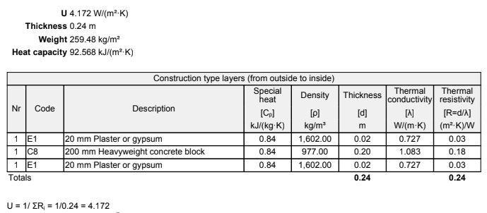
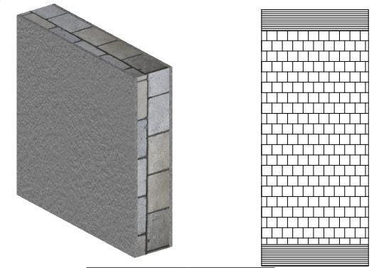
In the calculation for the first building element, which was the wall element, the three most common materials were used when building in a tabular form to calculate the heat capacity, the density, the thickness, the thermal conductivity and the thermal resistance of the three different layers or materials that constitute the wall element as a whole.
WALL ELEMENTInternational Journal of Civil and Structural Engineering Research ISSN 2348-7607 (Online) Vol. 6, Issue 2, pp: (99-108), Month: October 2018 - March 2019, Available at: www.researchpublish.com
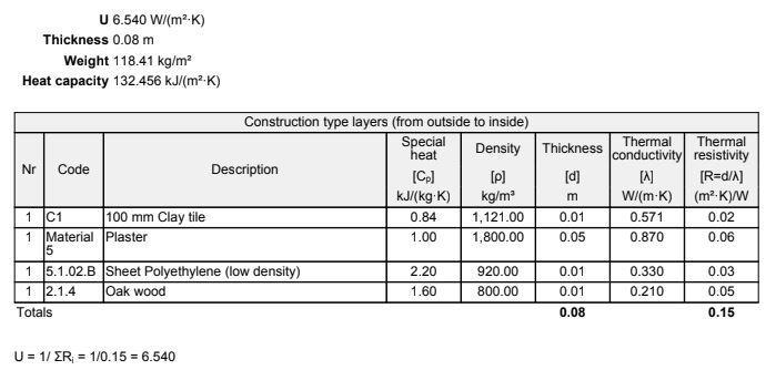
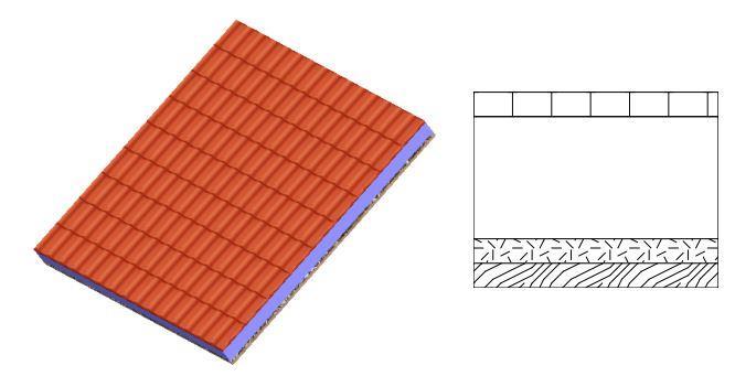
In the calculation for the second building element, which was the roof element, this calculation is also done by considering four of the most commonly used roofing materials used in Famagusta which includes the use of clay tiles, the plaster board, the water insulation sheet and the oak wood rafters or roof members. Thereby giving the total calculations of the roof elements as a whole
 ROOF
ROOF
International Journal of Civil and Structural Engineering Research ISSN 2348-7607 (Online) Vol. 6, Issue 2, pp: (99-108), Month: October 2018 - March 2019, Available at: www.researchpublish.com
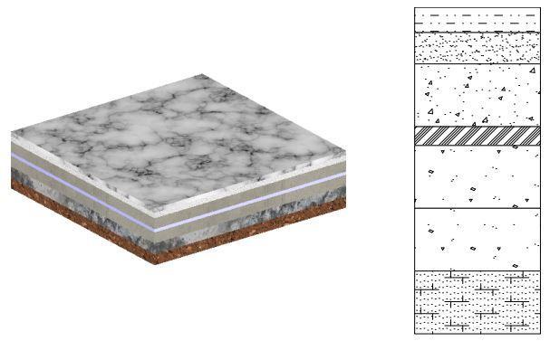
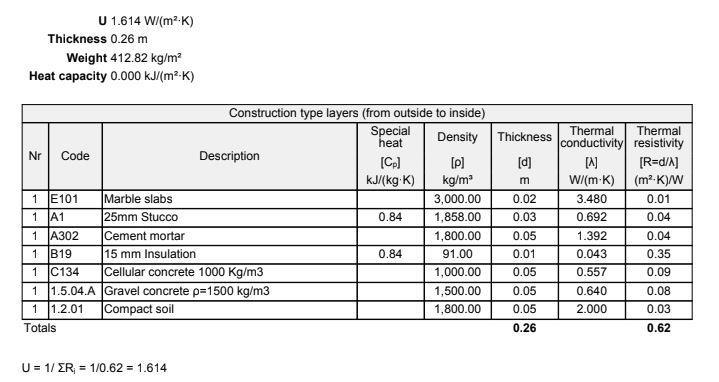
In the calculation for the third building element, which was the floor element, the calculation is also done by considering seven of the most commonly used floor materials used in Famagusta FLOOR
International Journal of Civil and Structural Engineering Research ISSN 2348-7607 (Online) Vol. 6, Issue 2, pp: (99-108), Month: October 2018 - March 2019, Available at: www.researchpublish.com
4. RESULTS/ CONCLUSION
With the use of the simulation software, the density, thermal conductivity, thermal resistivity were calculated based on the density and the thickness of these materials and in turn the component as a whole which gives us a direct value of the heat transmittance or heat conductivity of each building element.
In the calculation for the first building element, which was the wall element, the three most common materials were used when building in a tabular form to calculate the heat capacity, the density, the thickness, the thermal conductivity and the thermal resistance of the three different layers or materials that constitute the wall element as a whole.
In the calculation for the second building element, which was the roof element, this calculation is also done by considering four of the most commonly used roofing materials used in Famagusta which includes the use of clay tiles, the plaster board, the water insulation sheet and the oak wood rafters or roof members. Thereby giving the total calculations of the roof elements as a whole.
In the calculation for the third building element, which was the floor element, the calculation is also done by considering seven of the most commonly used floor materials used in Famagusta.
This will greatly help in the determination of the thermal comfort of the spaces which these elements form and create and also give builders the ability to either add or remove more layers depending on the kind or range of thermal comfort needed to be achieved for the user in the city of Famagusta
REFERENCES
[1] Pedersen CO. Advanced zone simulation in Energy Plus: incorporation of variable properties and phase change material (PCM) capability. Build Simul 2007; 2007: 1341–1345.
[2] Tabares-Velasco PC, Christensen C and Bianchi M. Verification and validation of EnergyPlus phase change material model for opaque wall assemblies. Build Environ 2012; 54: 186–196.
[3] Zhuang C, Deng A, Chen Y, et al. Validation of veracity on simulating the indoor temperature in PCM lightweight building by EnergyPlus. In: International conference on life system modeling and simulation/international conference on intelligent computing for sustainable energy and environment, Wuxi, China, 17–20 September 2010, pp. 486–496. Berlin Heidelberg: Springer.
[4] Florides GA, Kalogirou SA, Tassou SA, et al. Modeling of the modern houses of Cyprus and energy consumption analysis. Energy 2000; 25: 915–937.
[5] Lapithis P, Efstathiades C and Hadjimichael G. Technical improvement of housing envelopes in Cyprus. In: Braganca L, Wetzel C, Buhagiar V, Verhoef LGW (eds) Improving the quality of existing urban building envelopes facades and roofs. Amsterdam: IOS Press, 2007, pp.9–20.
[6] Rabah K. Development of energy-efficient passive solar building design in Nicosia Cyprus. Renew Energy 2005; 30: 937–956.
[7] Ozdeniz MB and Hancer P. Suitable roof constructions for warm climates Gazimag˘usa case. Energy Build 2005; 37: 643–649.
[8] Kalogirou SA, Florides G and Tassou S. Energy analysis of buildings employing thermal mass in Cyprus. Renew Energy 2002; 27: 353–368.
[9] Panayiotou GP, Kalogirou SA, Florides GA, et al. The characteristics and the energy behaviour of the residential building stock of Cyprus in view of Directive 2002/ 91/EC. Energy Build 2010; 42: 2083–2089.
[10] Pilavachi PA, Kalampalikas NG, Kakouris MK, et al. The energy policy of the Republic of Cyprus. Energy 2009; 34: 547–554.
[11] Baetens R, Jelle BP and Gustavsen A. Phase change materials for building applications: a state-of-the-art review. Energy Build 2010; 42: 1361–1368.
[12] Hawes D, Feldman D and Banu D. Latent heat storage in building materials. Energy Build 1993; 20: 77–86.
International Journal of Civil and Structural Engineering Research ISSN 2348-7607 (Online) Vol. 6, Issue 2, pp: (99-108), Month: October 2018 - March 2019, Available at: www.researchpublish.com
[13] Zhang Y, Zhou G, Lin K, et al. Application of latent heat thermal energy storage in buildings: stateof-the-art and outlook. Build Environ 2007; 42: 2197–2209.
[14] Zhang D, Li Z, Zhou J, et al. Development of thermal energy storage concrete. Cem Concr Res 2004; 34: 927–934.
[15] Schossig P, Henning H, Gschwander S, et al. Microencapsulated phase-change materials integrated into construction materials. Sol Energy Mater Sol Cells 2005; 89: 297–306.
[16] Kaasinen H. The absorption of phase change substances into commonly used building materials. Sol Energy Mater Sol Cells 1992; 27: 173–179.
[17] Zalba B, Marin J, Cabeza L, et al. Review on thermal energy storage with phase change: materials, heat transfer analysis and applications. Appl Therm Eng 2003; 23: 251–283.
[18] Mehling H and Cabeza LF. Heat and cold storage with PCM. Heat and mass transfer. Berlin, Heidelberg: Springer, www.springerlink.com/index/10.1007/978-3- 540-68557-9 (2008, 10 November 2010).
[19] Origgi D. Influence of thermal insulation and phase-change material on energy demand and CO 2 – emissions in different european climates. construction materials. Darmstadt: Passive House Institute, 2006.
[20] BASF. Micronal PCM intelligent temperature management for Buildings. technology. Ludwigshafen, Germany: BASF The Chemical Company, 2009.
[21] Valentin Energie Software. PCM Express. Freiburg: Valentine Software, www.valentin.de/en/products/pcm/ 58/pcm-express (2008, acccessed 11 August 2015).
[22] U.S.Department of Energy. Getting started with EnergyPlus, basic concepts manual – essential information you need about running EnergyPlus. building. Berkley, California: U.S. Department of Energy, 2011.
[23] ASHRAE. Design. In: Owen MS (ed.) ASHRAE handbook of fundamentals, SI edition. Atlanta: American Society of Heating, Refrigerating and AirConditioning Engineers, 2009, pp.18.
