International Journal of Civil and Structural Engineering Research ISSN 2348-7607 (Online) Vol. 6, Issue 2, pp: (260-269), Month: October 2018 - March 2019, Available at: www.researchpublish.com
Analysis and Design of Three Lane Highway Bridge with Constraints
Madhu M Department of Civil Engineering, Sri Siddartha Institute of Technology, TumkurAbstract: Bridges are the permanent structures which carry vehicular load or other moving load to pass through an obstacle. During the process of construction, we encounter various geometrical constraints and operational constraints due to the existing site condition. It is therefore necessary to identify the constraints in order to provide an efficient planning and optimum design. Thus, the paper presents the analysis and design of a 3-lane highway bridge with constraints. A bridge to carry a three-lane highway across a series of existing rail tracks and sidings underneath and a highway viaduct which the new highway bridge has to pass beneath is to be analysed and designed. A minimum horizontal clearance of 4.5 m shall be provided between any rail and the face of any piers or abutments to the new bridge above ground level, to avoid the need to design these elements for accidental impact. The bridge is designed for the vehicular loads as per IRC-06 2016. The bridge is modelled for simply supported and continuous span with pre-stressed precast SY Girder and SY Edge girder and is compared to that of an I girder with other bridge components having regular dimensions designed as per the India standard codes for the forces acting on the bridge structure. The comparison of displacements, moments and load carrying capacity of the above modelled structures are presented and discussed. Thus from the analysis report obtained, the structural response like displacements, moments and forces for the continuous span SY girder is less compared to that of the I girder for the same cross sectional area. Therefore from this paper it is evident that for the bridges of span greater than 20 m up to 40 m, SY beam provides an economical section.
Keywords: SY girder, I girder, Simply Supported Span, Continuous Span.
I. INTRODUCTION
1.1 Existing System
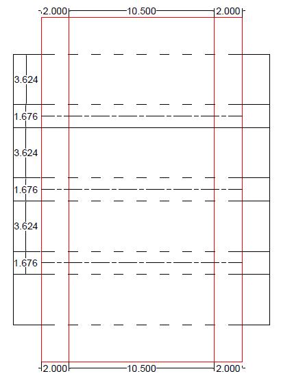
A Railway track with 2 sidings whose gauge length is 1.676 m. [Broad Gauge, IRC standards] The Intermediate distance between the railway track is 3.624. Hence the total width sums upto12.276 m.
Fig 1.1: Showing Railway Track underneath the New Highway Bridge to be constructed
International Journal of Civil and Structural Engineering Research ISSN 2348-7607 (Online) Vol. 6, Issue 2, pp: (260-269), Month: October 2018 - March 2019, Available at: www.researchpublish.com
A Viaduct at the height of 16.5 m (bearing level) from Ground level consists of continuous 6-span box girder deck, resting on bearings. The precast segmental structure has 192 spans with max span of 80 m of single cell box. There are 39 sections of segmental bridge which forms the viaduct using 2800 individual sections with 3 to 8 span continuous structure and 2 cast insitu bridges. Segmental bridge are supported monolithically at intermediate piers and bearings on both side and at the ramp structure it is connected to west Kowloon highway with minimum horizontal radius of 250 m. the load of individual pier at critical section is 1044 KN[1]
Fig 1.2 (a): Typical Elevation of the Viaduct
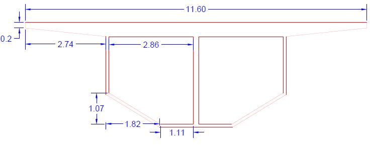
Fig 1.2 (b): Typical Section of the Viaduct
1.2 Problem Statement
A highway bridge of 11m wide with foot path on either side measuring 2 m is to be constructed across the existing railway track. The vertical alignment of the new highway is constrained by the presence of an existing highway viaduct which the new highway has to pass beneath. The 30 m span critical section of a highway bridge is to be analysed and designed with the following mentioned geometrical constraints
The clearance height of minimum 5m for movement of trains should not get disturbed
The minimum width of 4.5m needs to be left for the protection of piers construction of piers in between the rail tracks.

The minimum traffic clearance of 5.7m for new highway, since a viaduct passes over the bridge
Construction of piles should be taken care of such that the boring should not disturb the already placed piles for viaduct
The required minimum clearance to the overhead viaduct must be achieved for the completed new bridge. The minimum clearance to the existing railway must be achieved at all times during construction and for the completed new bridge. A minimum horizontal clearance of 4.5 m shall be provided between any rail and the face of any piers or abutments to the new bridge above ground level, to avoid the need to design these elements for accidental impact
II. METHODOLOGY
2.1 Alignment Proposal for the new highway bridge with identified constraints
a. Vertical Alignment
Due to the presence of railway track, 7.5 m clearance height is provided for movement of single deck and double deck train. So the bearing level of the new highway bridge to be constructed is proposed at 7.85 m from the ground level. From this it is evident that height of the bridge pier is 7.85 m. Bearings of 320mm are assumed. Girder of 1.5 m height is
International Journal of Civil and Structural Engineering Research ISSN 2348-7607 (Online) Vol. 6, Issue 2, pp: (260-269), Month: October 2018 - March 2019, Available at: www.researchpublish.com
considered. Deck of 0.55 m is adopted based on span/depth ratio which is 38. Hence 5.73 m clearance is provided for vehicular movement for the new highway bridge which is therefore sufficient. This sets the vertical alignment for the bridge.
b. Horizontal Alignment
Due to the presence of highway viaduct, it is mandatory to check the vertical stress at the base of foundation and ensure that the stresses due to new highway bridge and existing viaduct do not overlap causing stress overburden which leads to geotechnical failure.
So we use Boussinesq equation to find the quantity of stress at the required depth (z), which is given by σz= KB(Q/z2) where KB=(3/2π)/(1+(r/z)2)5/2
Q1=1044 KN (Load from Highway Bridge) Q2=1050 KN (Load from Viaduct)
Table 2 1: showing Vertical Stress at Different Depth Unit of Stress is in KN/m2
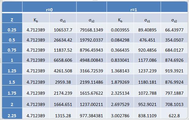
Fig 2.1: Vertical Stress Plot at the Base of the Foundation
Based on the Boussinesq Equation, 3 m distance away from the foundation of viaduct is sufficient for stresses not to overlap with each other. But minimum of 4.5 m is provided for the protection and construction of piers in between the rail tracks.
2.2Determination of Loads
Carriage way = 10.5 m
Span = 10.5+0.25+0.25 =11 m
Wearing Coat = 65 mm
Type of Loading = IRC Class AA Loading / 70R Loading
The Live Load from IRC Class AA Loading / 70R Loading [2]
Calculation of Effective Width of Dispersion

International Journal of Civil and Structural Engineering Research ISSN 2348-7607 (Online) Vol. 6, Issue 2, pp: (260-269), Month: October 2018 - March 2019, Available at: www.researchpublish.com
be = Kx (1-(x/l) + bw x = l/2 =11/2
k is based on b/L = 11/ 10.5 = 1.047
Therefore k = 2.64 bw=w+2h be=k*l/2*(1-(l/2*1) +bw bw=1.05+2(0.065) be =2.64*11/2*(1-(11/2*1) +1.18 bw=1.18 m be =8.44 m
Effective length of dispersion (dL)
dL = Length of tyre contact +2(Overall depth of deck slab including wearing coat) = 3600+2(550+65) = 4.83 m

Total Load including Impact = 700*1.10 = 770 KN
Effective width of dispersion of 2 Tracks
Fig 2.2: Effective Width of dispersion
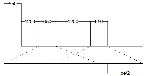
Effective Width of dispersion = 550+1200+850+1200+(850/2)+(bc/2) = 7.68 m
Average Intensity of Loading = 770/ (7.68*4.83) = 20.75 m
Max Bending Moment
Fig 2.3: Showing loading diagram on the carriage way
Research Publish Journals
International Journal of Civil and Structural Engineering Research ISSN 2348-7607 (Online) Vol. 6, Issue 2, pp: (260-269), Month: October 2018 - March 2019, Available at: www.researchpublish.com
BM|c = ∑V= 0 => RA+ RB = 20.75*4.83
RA+ RB = 100.22 KN RA=RB = 50.11 KN
∑M= 0 => = 50.11(5.5)-20.75(2.415)*(2.415/2) = 275.605-60.50 = 215.09 KN
Net Effective width of dispersion for all 4 Wheels = 550+1200+150+450+150+850+150+450+ (150/2) + (7.03/2) = 4.029 m
Total Load = (200+200)*1.25 = 500 KN
Intensity of Loading = 500/ (7.03*2.64) = 26.94 KN/m
Summary of Load Calculation
Table 2.2: Summary of Load calculation
Type of Vehicle Tracked Vehicle Wheeled Vehicle
Total Load in KN 770 500 Load Intensity in KN/m 20.75 26.94 Shear Force in KN 50.11 38.25 Bending Moment in KN-m 215.09 183.21
Total Live Load =770+500+300 =1570 KN
Reduction in Load due to Longitudinal Effect
Reduction due to Longitudinal Effect = 10% IRC 6 2016 Clause 205 table 8
Reduced Live Load = 1570-0.1(1570) = 0.9*1570 = 1413 KN
2.3Modelling the structure
Structural Parameters
Deck Slab of 16 m wide and 0.55 m deep is considered with concrete grade of M25 and Fe 500 steel and concrete haunch thickness of 0.075 m is assumed
Two type girders are compared with one another for their structural efficiency.4 Girders are placed along the carriage way with 3.6 m spacing
International Journal of Civil and Structural Engineering Research ISSN 2348-7607 (Online) Vol. 6, Issue 2, pp: (260-269), Month: October 2018 - March 2019, Available at: www.researchpublish.com
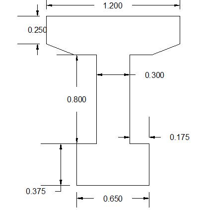
Fig 2.4: Section of (a). I Girder (b). SY Girder
I girder with the cross-sectional area of 0.8625 m2 is compared with precast pre-stressed SY girder[3] of equal cross sectional area with pre stressing force of 444.822 KN and parabolic profile of tendons.


The bearings are fixed i.e., translations and rotations are not allowed.
Piers of 2m diameter and 7.85 m height are considered.
Models are modelled using the software CSi Bridge
M1- Continuous Span with I girder M2- Continuous Span with SY girder M3- Discontinuous Span with I girder M4- Discontinuous Span with SY girder
3 Analysis of the Model
The bridge is modelled and is analysed using CSiBridge-v-20
4 Design Calculations of Final solution
The bridge is manually designed as per the Indian Standard codal provisions Behaviour of continuous span and discontinuous span girder structure and method of Pre-stressing In continuous structure, the bridge is provided with single bearing line. The indeterminate 3 span girder is released by hinges at the support to make it a determinant structure. The structure experiences a central moment of wl2/8 where w is the load applied on the beam per meter run. The beams deflect and the end rotations will be θ= Mmax X l/3EI. Since the structure is continuous, hogging moment are applied at intermediate support so that the rotations are compatible. The uniform load on the statically determinant beam is provided with parabolic pre-stressing cable with a force equal to the force acting on the structure. The pre-stressing force (P) with an eccentricity (ec) at mid span is applied in the upward direction. Thus the moment at center is Pec and moment at any other point will be Pe. The eccentricity is under the control of the designer to balance the load in case of the pre-stress bridges [4]
Fig 2.5: Continuous Span showing Single Bearing
International Journal of Civil and Structural Engineering Research ISSN 2348-7607 (Online) Vol. 6, Issue 2, pp: (260-269), Month: October 2018 - March 2019, Available at: www.researchpublish.com
In discontinuous structure, the bridge is provided with double bearing. When the structure with discontinuous support is acted upon load, moments are produced at the mid-point equal to wl2/8. The end supports and intermediate supports would not carry any moment. The required pre-stressing force is given to the member through tendons considering the effect of losses due to pre-stress[5]
Fig 2.6: Discontinuous Span with double bearing III.
RESULTS AND DISCUSSIONS
3.1Axial Load under Dead Load, Moving Load and Pre-stressing Load
Behaviour due to Axial Load
Axis Title
0 500 1000 1500 2000 2500 3000 3500 4000 4500 M1 M2 M3 M4
Prestressed Load Moving Load (-ve) Moving Load (+ve) Dead Load

Fig 3.1: Variation of Axial Load in 4 models due to Dead Load, Moving Load and Pre-stressed Load
The Axial Load for the Continuous Span SY girder under DL, ML and PL is less compared to the other 3 types of span girder combination. The value of Axial Load for DL, ML (+ve), ML (-ve) and PL are 1002.154 KN, 2387.106 KN (+ve), 54.721 KN (-ve), and 62.043 KN respectively. The reduction in the axial load is due to the geometry of the SY girder which distributes the load applied equally thus not inducing the local stress in the member. Since the continuous span takes up the load and the moment, the forces that are created in the object are reduced than compared to the discontinuous span girder[6]. The variation of axial load is slightly on a higher scale on 60% when comparison is made between Continuous and discontinuous span. The change in girder section from I to SY reduces the axial load by 15%
International Journal of Civil and Structural Engineering Research ISSN 2348-7607 (Online) Vol. 6, Issue 2, pp: (260-269), Month: October 2018 - March 2019, Available at: www.researchpublish.com
3.2Bending Moment under Dead Load, Moving Load and Pre-stressing Load
Behaviour due to Bending Moment
Prestressed Load(ve)
Prestressed Load (+ve)
Load (-ve)
Load (+ve)
M1 M2 M3 M4
Fig 3.2: Variation of Bending Moment in 4 models due to Dead Load, Moving Load and Pre-stressed Load
The Dead load Moment for the SY girder with the continuous span is less since the moment of Inertia of the member is less compared to the other three members. The inertia about the 3 axis is about 50 % more than that of I girder. Thus the ability of the beam to resist bending will be more for the section with high moment of Inertia. The moment of Inertia is a geometrical property. In case of a discontinuous support, the support does not take any moments and hence there is huge positive moment resulting in large sections. The continuous span creates a negative moment providing slender stable sections.
The moving load moment is lesser for discontinuous span with SY girder whose value is 2605.79 KN-m. The moment due to moving load is a characteristic of lane thickness, vehicle load, wheel spacing and spanning load. The moment calculation due to moving load is based on the concept of influence line diagram. The nodal displacements reactions and member forces are produced for specified moving load[7]The moment due to pre-stressing force is due to pre-stressing force (Po) acting at an eccentricity (ec). The resulting hogging moment is Poec for positive values of ec. This is termed as primary moment. For the given tendon profile, the primary moment deflects upwards and since the ends are restrained against deflection, there is negative moments which are produced in the beam termed as secondary moments [8]. Based on this principle, the SY girder with continuous span yields the minimum Pre-stressing Moments
The variation of bending moment is more than 20% when comparison is made between Continuous and discontinuous span. The change in girder section from I to SY reduces the moment by 15% 3.3
Behaviour due to Longitudinal Displacement
Prestressed Load(ve)
Prestressed Load (+ve)
Moving Load (-ve) Moving Load (+ve)
M1 M2 M3 M4
International Journal of Civil and Structural Engineering Research ISSN 2348-7607 (Online) Vol. 6, Issue 2, pp: (260-269), Month: October 2018 - March 2019, Available at: www.researchpublish.com
The longitudinal displacement due to dead load for the girders is lesser in case of continuous span with SY girder whose value is equal to 2.941x10⁻⁵ m under dead load case. The longitudinal displacement in a bridge can be due to the deformation of the elastic pier, deformation due to soil and foundation, displacement due to non-synchronous pier excitation, displacement caused due to inelastic pier deformations. About 50 % of the girder displacement is due to non synchronous displacement of pier excitation. Since pier excitation is dominant in discontinuous span, their displacements are greater compared to continuous spans and the ability to resist deformation is the function of moment of inertia, SY girder with continuous span has lesser displacements
The longitudinal displacements in the girder due to moving load are negligible in case of discontinuous spans and are predominant in continuous spans. It is because of the non-linear deformation of the pier where stiffness is positive to the limit displacement which corresponds to the maximum displacements that causes bearing movement in case of a continuous span resulting in large deformations. For displacement based design of bridges, the continuous spanned bridges are considered.
The longitudinal deflections in pre-stressing elements are due to the combination of deflection caused due to the prestressing force and the deflection that is caused due to the gravity loads. The net pre-stressing force acting on a member causing displacements is the pre-stressing forces after all the losses. The displacements due to the pre-stressing force are min for the continuous span with SY girder which is 9.42x10⁻⁵m but is greater than the displacement caused due to dead load. That is because the resultant displacement is due to both dead load and pre-stressing load.
3.4Vertical Displacement under Dead Load, Moving Load and Pre-stressing Load
Behaviour due to Vertical Displacement
Prestressed Load(ve)
300
200
100
0
400 M1 M2 M3 M4
Prestressed Load (+ve) Moving Load (-ve) Moving Load (+ve)
Fig 3.4: Variation of Axial Load in 4 models due to Dead Load, Moving Load and Pre-stressed Load
The vertical displacements in bridge are more important than the horizontal and transverse displacement. It accounts for the serviceability of the bridge. From the above results it is evident that the vertical deflections are lesser in continuous spans than in discontinuous spans. The factors on which the vertical deflection depends are on loads, water content, cement-content. The shrinkage and creep being the inherent property of cement, the differential shrinkage and creep which arises in discontinuous structure increases vertical deflection over a period of time. And also proper design of prestressing elements in the bridge structure also eliminates the long term vertical displacements [9]
The displacement for moving load is varying based on the support condition. It is less in continuous support and is invariably high in case of discontinuous support. That is due to the increase in stiffness in conjunction point in case of the continuous support which is absent in discontinuous support leading to excessive deflection.
The vertical displacement due to the pre-stressing force is upward due to the pre-stressing force applied to the tendons. The structure is under compression due to the high pre-stressing force and deflection increase with increase in load and the structure behave monolithically. With increase in load, there is rupture or a crack which reduces stiffness in the discontinuous structure
International Journal of Civil and Structural Engineering Research ISSN 2348-7607 (Online) Vol. 6, Issue 2, pp: (260-269), Month: October 2018 - March 2019, Available at: www.researchpublish.com
3.5Proposed Solution
Highway bridge sub-structure of 7.85 m from ground level and super structure of 2.42 m is proposed with 7.5 m clearance for movement of train and 5.73 m clearance for vehicular movement on new highway bridge
Cast in situ deck form of 550 mm depth is being using for the deck slab of the bridge
Precast pre-stressed SY beams with continuous span are considered for the bridge beams
Elastomeric bearings of the size 0.32X0.5X0.6 m of 4 numbers are provided at the top of the pier cap.
Piers are designed as columns with the vertical load of 1232 KN, Longitudinal moment of 3686.75 KN-m, Transverse Moment of 5102 KN-m
IV. CONCLUSIONS
1. Vertical Alignment is fixed at 4.5 m from the base of the footing of the viaduct to prevent overburden stress at the base of the foundation and for the protection and construction of piers in between the rail tracks
2. The comparative study on the on two types of girders with their end condition depicts that continuous span with SY girder is to be adopted for design for the following reasons.
Reduced axial load due to its geometry which hinders the local stress in the structure
Design of Slender Section due to great reduced Negative Moment
Reduced Longitudinal displacements as the Moment of Inertia for SY girder is higher and its ability to resist deformation is more
Reduced Transverse displacement due to its stiffness property
Reduced Vertical displacement as there is in differential shrinkage and creep due to its continuous support
3. From the forces and moments obtained from the CSi Bridge V-20.0 software the various components of the bridge are designed
Bearings of the size 0.32X0.5X0.6 m of 4 numbers are provided at the top of the pier cap.
Piers are designed as columns with the vertical load of 1232 KN, Longitudinal moment of 3686.75 KN-m, Transverse Moment of 5102 KN-m
REFERENCES
[1] C. A. O. Shengfa, W. C. O. WU, T. U. Jing, and E. WU, “Design & Construction of Ngong Shuen Chau Viaduct,” Int. Conf. Bridg. Eng. 21st Century, vol. 1, 2006.
[2] “STANDARD SPECIFICATIONS AND CODE OF PRACTICE FOR STANDARD SPECIFICATIONS AND CODE OF PRACTICE FOR Road Bridges,” in Irc: 06-2016, 2000, pp. 9–10.
[3] G. Toniolo and M. di Prisco, “Prestressed Beams,” pp. 711–833, 2017.
[4] C. L. Freyermuth, “Design of Continuous Highway Bridges with Precast, Prestressed Concrete Girders,” PCI J., pp. 14–39, 1969.
[5] Ta. Bin Mehmood, “Talha bin mehmood seat no: ce-013/2011-12 ce-512 (bridge analysis and design),” 2011.
[6] A. I. of S. Structure, moments-shears-and-reactions-for-continuous-highway-bridges.pdf. .
[7] S. Group, “Bridges & elevated structures.”
[8] J. R. LIBBY and N. D. PERKINS, “Modern Prestressed Concrete Highway Bridge Superstructures.”
[9] C. R. C. P. Llc, Bridge Engineering Handbook. 2000.
