

SWING
REINKE MANUFACTURING CO., INC. DESHLER, NE USA
Josiah Carey Electrical Engineer, Reinke Manufacturing Co., Inc. 1040 Road 5300
Deshler, NE 68340
Voice: 402-365-7251 josiahcarey@reinke.com
Cody Bailey Director of Engineering, Reinke Manufacturing Co., Inc. 1040 Road 5300
Deshler, NE 68340
Voice: 402-365-7251 codybailey@reinke.com
SUMMARY
Mechanized irrigation systems are vital to many agriculture-based operations globally and used to drive operational efficiencies while improving water management. Opportunities to increase water use efficiencies under swing arm corner spans exist which is the primary purpose of this paper. This paper is put forth to inform university, public and private sectors regarding the methods used on Reinke’s Electronic Swing Arm Corner (ESAC).
INTRODUCTION
A mechanized irrigation system enables producers and operators globally to manage water resources and, in some instances, other liquids. This type of system can enable application of an optimal amount of water at critical times during a crop’s life cycle, fortifying crop health and maximizing yield potential. While there are many components that make up a mechanized irrigation system, in a general sense, such a system includes a mechanical structure, a drivetrain, and a control system.
One common type of mechanized irrigation system is a center pivot arrangement that includes a central pivot point about which the system rotates, swivels, or revolves. A “span”, as the term is used herein, is a structural assembly comprised of a portion of the irrigation pipeline, struts and braces, and a truss rod connection system. A span travels in a fixed circular operation in relation to the central pivot point. The path of travel is determined by the span’s radial position with respect to the central pivot point. Hence, the particular area capable of being irrigated by a span can be ascertained through standard mathematical calculations known to those having ordinary skill in the art
This, in turn, permits optimal water capacity or distribution to be determined and far more predictable. Most of the papers and journals related to center pivots discuss this type of span. (Derrel Martin, 2017)

Page 2 of 9
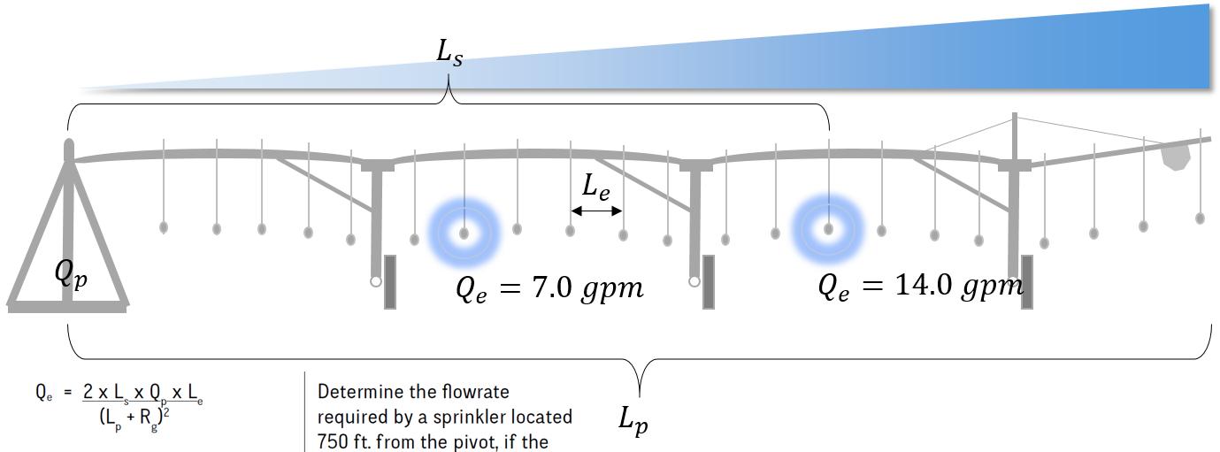
(Nelson Irrigation Corporation) Flow
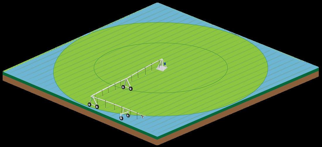
Although central-pivot-type irrigation systems function satisfactorily for the most part, they are capable of watering only circular areas. Most plots of land, however, are not circular in shape, but are of some other shape, the most common of which is square. A basic central pivot machine is not able to irrigate the corner areas of square-like fields or other areas outside of the circle covered by the machine. Accordingly, various types of attachments have been proposed to more adequately cover the sizeable land area represented by field corners. One successful type of corner irrigation system incorporates an ancillary span, or swing arm corner span (SAC), which is added onto an outermost end of a primary center pivot system.
Manufacturing Co., Inc., 2020)
A SAC is generally similar in construction to the spans of the primary irrigation pipeline, except that it has a hinge connection with the outermost end (relative to the central pivot point) of the primary irrigation pipeline and is supported by a tower having steerable wheels (i.e., a steering tower or S-tower). As the primary irrigation pipeline turns about the central pivot point, the steering tower is able to pivot the ancillary span out into the corners of the field and to retract the ancillary span back behind (or in front) of the primary irrigation pipeline as the system departs from a corner. In this manner, the ancillary span provides controllable and moveable extension to the primary irrigation pipeline which is able to cover a substantial portion of each corner of the field.
HURDLES TO CALCULATING WATER USE EFFICIENCY
Determining optimal water capacity for irrigation systems incorporating a SAC is much more complex than performing the standard mathematical calculations for determining optimal water capacity for a circular area covered by a primary irrigation pipeline. This is due in part to the ability of the SAC to maneuver at different extension and retraction velocities independent of the primary irrigation pipeline. Thus, many prior-proposed and/or existing irrigation systems incorporating a SAC vary on water use efficiency within the corners of the field. As the SAC
Page 3 of 9
(Reinke
SAC span
extends out into a field corner, it travels faster than the primary irrigation pipeline; thus, underwatering can occur in the area covered by the ancillary span during its extension. Conversely, the swing arm corner span moves relatively slowly as it retracts out of the field corners; thus, over-watering can occur in the areas covered by the swing arm corner span as it folds back behind the primary irrigation pipeline. The overall result is that some areas near the field corners may be under-watered and other areas may be over-watered, and the effectiveness of the irrigation suffers accordingly.
Another issue that makes determining optimal water capacity for a SAC more complex when compared to a primary irrigation span is that the orientation of the SAC as it passes over the area to be irrigated is not constant. The uniformity of the water distribution accordingly suffers due to the changes that occur in the effective overall length of the irrigation system as the ancillary span extends out and then retracts back in. Stated differently, when the SAC is in its most retracted orientation with respect to the primary irrigation pipeline, a substantial length of the ancillary span may pass over the same point on the ground below the ancillary span. Conversely, when the SAC is at its most extended orientation, only the width of the pipeline may pass over a point on the ground.
Accordingly, in order to distribute water evenly, it is necessary to supply water to the machine at varying rates (because more water is required when the machine is operating at its maximum length than when it is at minimum length) or to activate and deactivate select sprinklers to control the amount of water being distributed from particular portions of the primary irrigation pipeline and/or the SAC at various times throughout the irrigation cycle.
Various SAC water application solutions are in use today. One such solution adjusts water distribution via one or more mechanical switches, known as a cam switches, which allow for a set of sprinkler groupings to activate during phases of the irrigation cycle when the ancillary span is extending or extended and a separate set of sprinkler groupings to activate during phases of the irrigation cycle when the ancillary span is retracting or retracted. However, this solution does not predict the maneuvers (e.g., extension, retraction and/or velocity) of an SAC but rather reacts to the SAC maneuvers through a hinge mechanism such that when the SAC is at a particular extension angle relative to the primary irrigation pipeline, a switch is activated or deactivated and, based on the configuration it controls, the corresponding grouping of sprinklers is likewise activated or deactivated.
Page 4 of 9
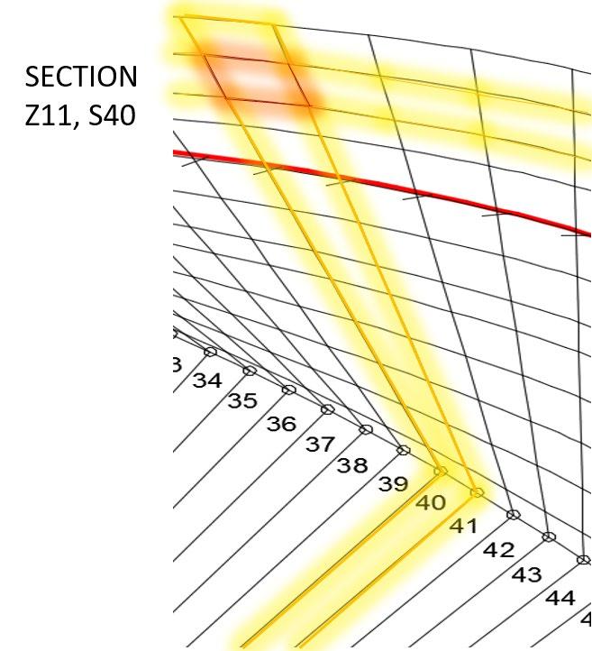
Field of interest representing mechanical switch sprinkler activations.
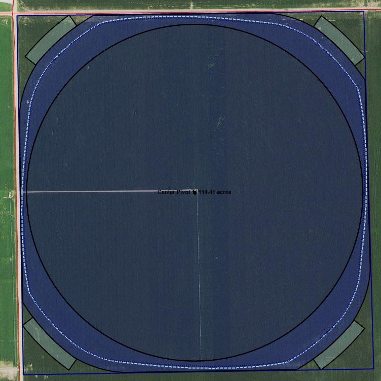
(Reinke Manufacturing Co., Inc. , 2020)
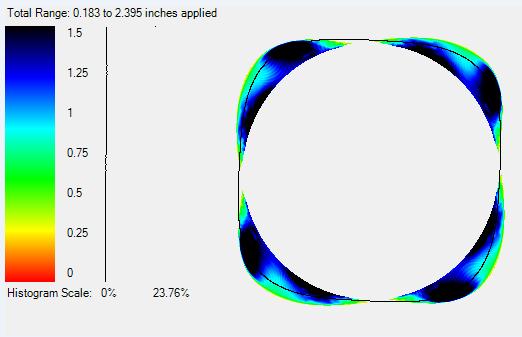
Field of interest representing mechanical switch sprinkler activations simulated to illustrate water application variations throughout the corners. A 1” water application target was used during the simulation.
Page 5 of 9
(Reinke Manufacturing Co., Inc. , 2020)
Other solutions designed to improve the uniformity and optimal distribution of water resources using the extension angle of the SAC relative to the primary irrigation pipeline as a means of controlling activation and deactivation of sprinkler groupings utilize a programmable logic controller (PLC). A PLC is used in lieu of a cam switch but has a similar effect. An irrigation system incorporating a PLC is able to control many more sprinkler groupings than a mechanical cam switch through the use of a programmable routine.
NORMALIZATION METHOD
To address these issues, a new method is used to normalize and calculate water use for a swing arm corner utilizing a path determined for a steering tower of an SAC that is comprised of a plurality of position-based coordinates. Knowledge of the position of the SAC steering tower (and thus the position of the SAC) relative to the determined path permits optimal water capacity or distribution for sections of the field-of-interest corresponding to the location of the steering tower at any given point throughout the irrigation cycle, such optimal water capacity or distribution being based upon a calculated area factor. In this way, the water application is determined based upon the actual path of travel. (United States of America Patent No. Patent Pending, 2019)
A path of travel is determined for the steering tower of the SAC. The area under the SAC is highly variable due to the number of maneuvers that can be taken by the SAC span. That is, during normal operations, the SAC can extend, retract and travel at increased or decreased velocities relative to the primary irrigation pipeline, even though it is coupled with the primary irrigation pipeline. The path of travel for the SAC steering tower is determined based upon the distance of the steering tower from the central pivot point and the angle of the ancillary span steering tower relative to the primary irrigation pipeline. Utilizing these two factors, a plurality of sectors and a plurality of zones may be defined within the area of the field-of-interest to be irrigated by the SAC. The result is a plurality of defined sections, or areas, each within a zone and a sector. (United States of America Patent No. Patent Pending, 2019)
Page 6 of 9
The area of each section is calculated, for instance, utilizing the shoelace algorithm attributed to Gauss, such algorithm being known to those having ordinary skill in the art, or a method similar thereto (United States of America Patent No. Patent Pending, 2019) The section having the largest area within each zone (i.e., the “prime section”) is used to determine maximum water capacity or demand required within the zone. Thus, by definition, the prime section within each zone will require the largest water demand. Sprinkler nozzle sizes for each zone on the ancillary span are selected to satisfy the water demand for the prime section. To avoid overwatering sections within the zone having smaller areas, area factors are determined by dividing the area of each other section within the zone by the area of the prime section. In this way, the water distribution within each section of a zone may be adjusted in accordance with its area factor, preventing overwatering of sections having smaller areas.

(United States of America Patent No. Patent Pending, 2019)
Page 7 of 9
REINKE’S ESAC SIMULATED STUDY
To evaluate the impact of this method a software simulator was developed. Using the systems configuration and known path of travel, a 10 ft (3.04 m) x 10 ft (3.04 m) grid is mapped corresponding to sections as determined under the SAC coverage area. Each grid is evaluated by ascertaining the amount of water applied within each area. This information can be used to calculate water use efficiency based on the target application depth.
Simulated normalization method based on SAC path of travel:
Statistical Results
Mean 0.975 in Median 1.024 in Standard Deviation 0.164 in Median Absolute Deviation 0.032 in Max 1.257 in
Minimum 0.236 in Data points 13,372
Christiansen Uniformity 90.514%
Histogram and visual representation of simulation with only the SAC coverage visible (black line depicts path of travel for the SAC).
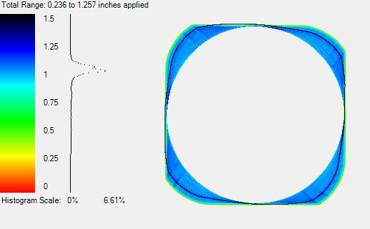
(Reinke Manufacturing Co., Inc. , 2020)
CONCLUSION
Through this normalization method, a significant increase in precision was observed from simulated studies over previous mechanical switch methods. This was confirmed over a multiyear field trial, 2018 – 2019, where a 43% increase was recorded. It is worth mentioning, the simulations predicted a 40% increase in precision so the actual field observations through SAC cup testing was greater.
Since the end of the field trial, further improvements to the sprinkler arrangements and methods have occurred. The simulated studies now reflect a 65% increase in precision over previous mechanical switch methods.
We now observe throughout the SAC coverage, including the areas during the SAC extension and retraction wherein times past were otherwise less than optimum, a Christiansen Uniformity exceeding 85% can be achieved. This has implications on the amount of acres that can qualify for precision irrigation funding programs such as the National Resources Conversation Service (NRCS) EQUIP program and other similar programs.
This level of precision allows the users to better utilize and manage water resources on highly maneuverable SAC spans where before, the precision was otherwise diminished due to the methodologies of that time.
WORKS CITED
Carey, J. e. (2019). United States of America Patent No. Patent Pending. Derrel Martin, e. a. (2017). Sprinkler Discharge. In e. a. Derrel Martin, CENTER PIVOT IRRIGATION MANAGEMENT HANDBOOK (p. 12). Lincoln, NE: Department of Biological Systems Engineering University of Nebraska-Lincoln. Nelson Irrigation Corporation. (n.d.). Required Flow for a Given Sprinkler. In Nelson Pocket Book (p. 16). Walla Walla, WA: Nelson Irrigation Corporation.
Reinke Manufacturing Co., Inc. . (2020, April 24). Chione Simulator . Deshler, Nebraska, United States of America .
Reinke Manufacturing Co., Inc. . (2020, April 24). Reinke Design Pro . Deshler , Nebraska , United States of America .
Reinke Manufacturing Co., Inc. (2020, April 22). Swing Arm Corner Illustration. Retrieved from www.reinke.com: https://www.reinke.com/uploads/5/9/4/2/59423143/sacgraphic-01_orig.png
Page 9 of 9