PORTFOLI

Raye Liu
Intern Architect, Alberta Association of Architects
Masters of Architecture (‘22), School of Architecture, Planning and Landscape, University of Calgary
Hours of Experience Required by Internship in Architecture Program by 2024-02-17 Requirement Total To Date Progress A. Design and Construction Documents 1. Programming 80 0 2. Site and Environmental Analysis 80 0 3. Schematic Design 240 310 4. Engineering Systems Integration 140 236.55 5. Building Cost Analysis 80 0 6. Code Research 120 69.25 7. Envelop Detailing 80 72.25 8. Design Development 320 357.5 9. Construction Documents 760 548.58 10. Specification and Material Research 120 6 11. Document Checking and Coordination 100 119.25 12. Energy Literacy / Sustainability 80 0 B. Construction Administration 13. Procurement and Contract Award 120 0 14. Construction Phase - Office 200 0 15. Construction Phase - Site 200 3 C. Management 16. Management of the Project 120 78.95 17. Business / Practice Management 120 4 GRAND TOTAL 1805.33 toward ExAC toward license
2


P 1 14 Canopy, Digital Fabrication Installation, Digital Fabrication 9-BLOCK RE-TIRE
20 Object, Parametric Design, Digital Fabrication FOLDING LIGHT BUILT INSTALLATIONS
3
2
3
SELECTED WORKS

P 22 Landscape Architecture, Parametric Design POUNCE
P32 Public, Cultural, Recreational COLLIDE
DESIGN SELECTED
4
4
5
CONCEPTUAL
WORKS

P P P 40 46 48 Residential, Retail, Healthcare, Construction Documentation Residential, Retail, Design Development CAMBIE GARDENS, PARCEL C BASSANO 6 7 TECHNICAL DESIGN SKETCHES 5
6 BUILT INSTALLATION
Photo credit: Potographer Neil Zeller
9-BLOCK
Built Installation 2020
Team project
Team members and roles:
Team Lead: Assistant Professor Mauricio Soto-Rubio
Lighting design (assembly system) and prototype (3D printing script and form design): Raye Liu
LED coding and installation: Shelby Christensen
Structure: Ji Song Sun, Jonathan Monfries
Digital Fabrication Specialist: Guy Gardner
Software: Rhino, Grasshopper, Photoshop, Illustrator
Tools and Equipment: Robotic arm 3D printing, CNC machine
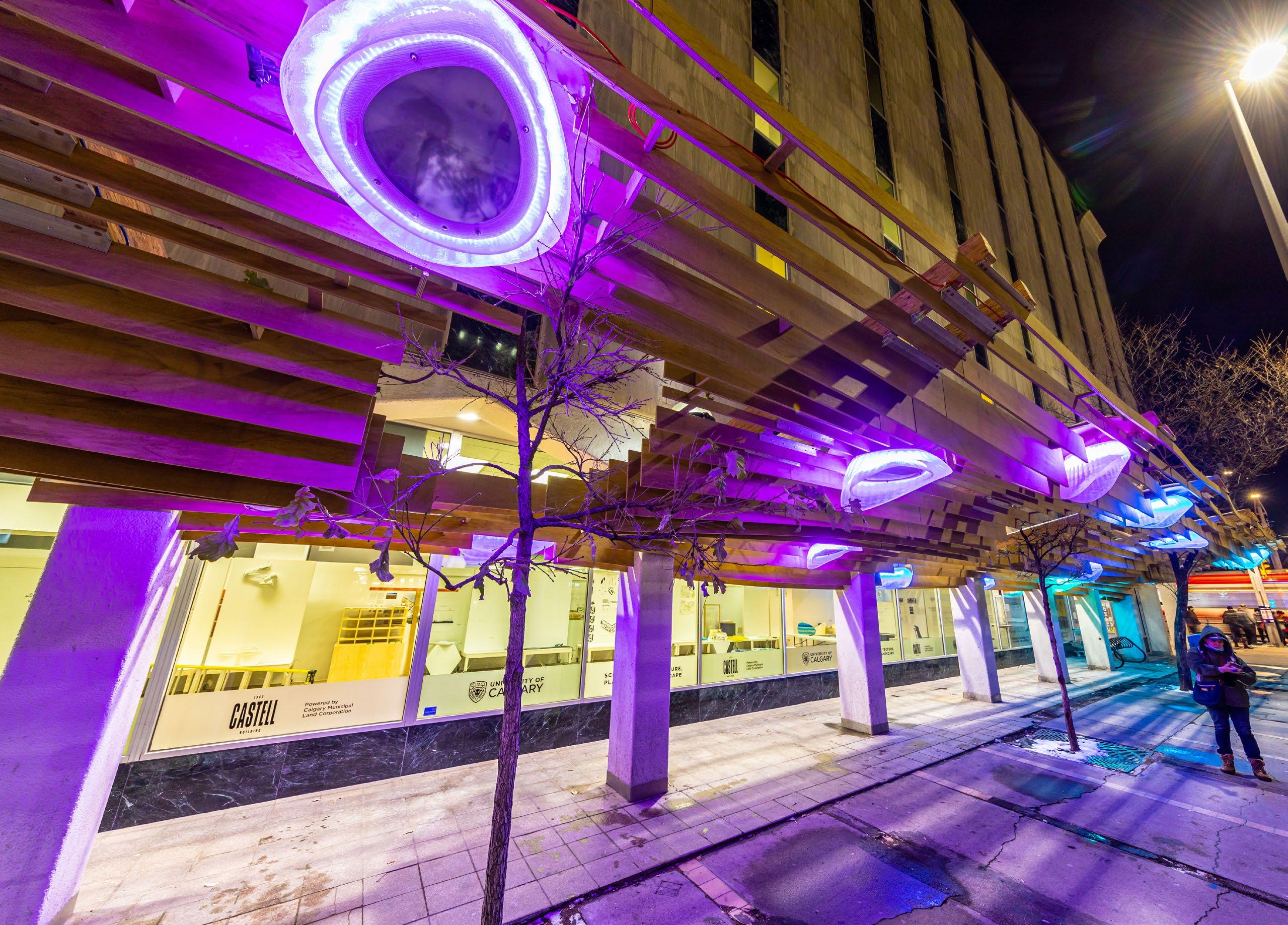
Initiated and commissioned by the City of Calgary, SAPL was selected as a collaborator to introduce a quick pilot solution in the nine blocks that surround City Hall. The main objective of this project is to improve vibrancy and sense of safety in this important area in downtown through a relatively low-cost but impactful design solutions.
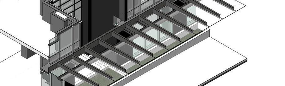
Situated on Macleod Trail and 7th Avenue SE, Calgary, the 9 block canopy project consists of an undulating plywood slat design that contains curvatures to provide a dynamic effect as pedestrians and vehicles pass through the site.
Project THE CITY OF CALGARY ENTUITIVE CITY OF CALGARY BUILDING PERMIT This drawing the property of the School of Architecture, shall not be used for any purpose or copied or communicated the written consent of the School of Architecture, Use only for the intended purpose as shown in description-revision the contractors responsibility to check all information GENERAL 1.1 DESIGN LIFE: 1.1.1. THE CANOPY STRUCTURE HAS BEEN DESIGN TEMPORARY INSTALLATION. 1.1.2. MEMBERS, MATERIALS, AND CONNECTIONS PROLONGED EXTERIOR EXPOSURE. EXTENSION ONE (1) YEAR DESIGN LIFE IS SUBJECT TO ENGINEERING 1.2 REFERENCE STANDARDS, CODES, AND ACTS 1.2.1. THE DESIGN AND CONSTRUCTION CONFORMS CODE ALBERTA EDITION 2019, ANY APPLICABLE HAVING JURISDICTION, AND THE LATEST EDITIONS STANDARDS OR PUBLICATIONS REFERENCED CAN/CSA-S16 LIMIT STATES DESIGN OF STEEL b) CAN/CSA G40.20/G40.21 STRUCTURAL QUALITY O86 ENGINEERING DESIGN IN WOOD (LIMIT 1.3 QUALIFICATIONS 1.3.1. ANY ORGANIZATION UNDERTAKING TO WELD CERTIFIED BY THE CANADIAN WELDING BUREAU. 1.4 CONNECTIONS TO EXISTING STRUCTURE 1.4.1. THE CANOPY INSTALLATION INTENDED TO THE CONDITION OF THE EXISTING BUILDING 2.2 THREADED ROD: CONFORM TO CAN/CSA-G40.20/G40.21 Fu =450 MPa). NUTS SHALL CONFORM TO ASTMA563. 2.3 PARALLEL STRAND LUMBER (PSL): MANUFACTURED PARALLAM AS MANUFACTURED BY WEYERHAEUSER EXECUTION 3.1 FABRICATION 3.1.1. ALL WELDS SHALL CONFORM TO CSA STANDARD 3.1.2. PROFILING, TAPERS, HOLES, AND THE LIKE ACCOMPLISHED BY CNC MACHINING OR OTHER NO OVERCUTTING. 3.2 INSTALLATION 3.2.1. ENSURE EXISTING CONCRETE ELEMENTS AT AND DRY PRIOR TO INSTALLATION. 3.2.2. SIDE STEEL PLATES SHALL BE INSTALLED ON CONCRETE COLUMN IN THE FOLLOWING MANNER: a) APPLY NEOPRENE PADS TO COLUMN FACE AND TAB PLATES AND EXISTING CONCRETE. b) INSTALL SIDE PLATES SO THAT PERPENDICULAR AND NOT IN CONTACT WITH THE NEOPRENE c) ALLOW THE SIDE PLATE TO ROTATE ABOUT COLUMN UNTIL THE TAB PLATES ARE IN CONTACT ‘LOCK’ ONTO THE COLUMN (CANTILEVER/STREET DOWN WITH THE BACK SIDE OF THE PLATE d) INSTALL THE THREADED RODS, WASHERS, TIGHT CONDITION. 3.2.3. INSTALLATION OF THE PSL BEAMS OR PRE-TENSIONING MAY PROCEED AT THIS POINT. 3.2.4. A DETAILED METHODOLOGY TO PRE-TENSION ESTABLISHED WITH THE ENGINEER AND THE 100 kN TENSION IS INDUCED IN THE ROD. 3.2.5. AFTER PRE-TENSIONING OF RODS AND FASTENING COMPLETED AND REVIEWED, THE REMAINDER LIGHTS, ELECTRICAL, ETC.) CAN PROCEED. 3.3 FULL SCALE LOAD TEST 3.3.1. A FULL SCALE LOAD TEST IS TO BE COMPLETED AND CONNECTION. THE INTENT OF THE LOAD PRETENSIONING PROCEDURE FOR THE THREADED BETWEEN THE STEEL PLATE, NEOPRENE PAD, 3.3.2. THE TEST IS TO BE CONDUCTED ON FULLY INSTALLATION OF SLATS, LIGHTS, ELECTRICAL, 3.3.3. THE TEST SHALL APPLY LOAD CONCENTRICALLY FROM THE FACE OF THE EXISTING COLUMN. 3.3.4. THE LOAD SHALL BE APPLIED IN CONTROLLED (2250 LBS) IS ESTABLISHED. THIS LOAD SHALL THE CONNECTION AT THE COLUMN MONITORED 3.3.5. APPROPRIATE SAFETY MEASURES (SUCH AS 3.3.6. AFTER THE TEST, INSPECT THE NEW AND EXISTING For tendering purposes only 0 PERMIT DRAWINGS A 1 2 3 1 2 3 B C D E F G A B C D E F G 7 Ave SE Macleod Trail SE Macleod Trail SE Macleod Trail SE University of Calgary City Building Design Lab (CBDL) Site Plan
7
16 lights in total for the whole canopy; the shapes vary depending on the undulation of the near slats, a design approach achieved through algorithm scripted in Grasshopper
Section
1000 0 500 250 mm
8 BUILT INSTALLATION
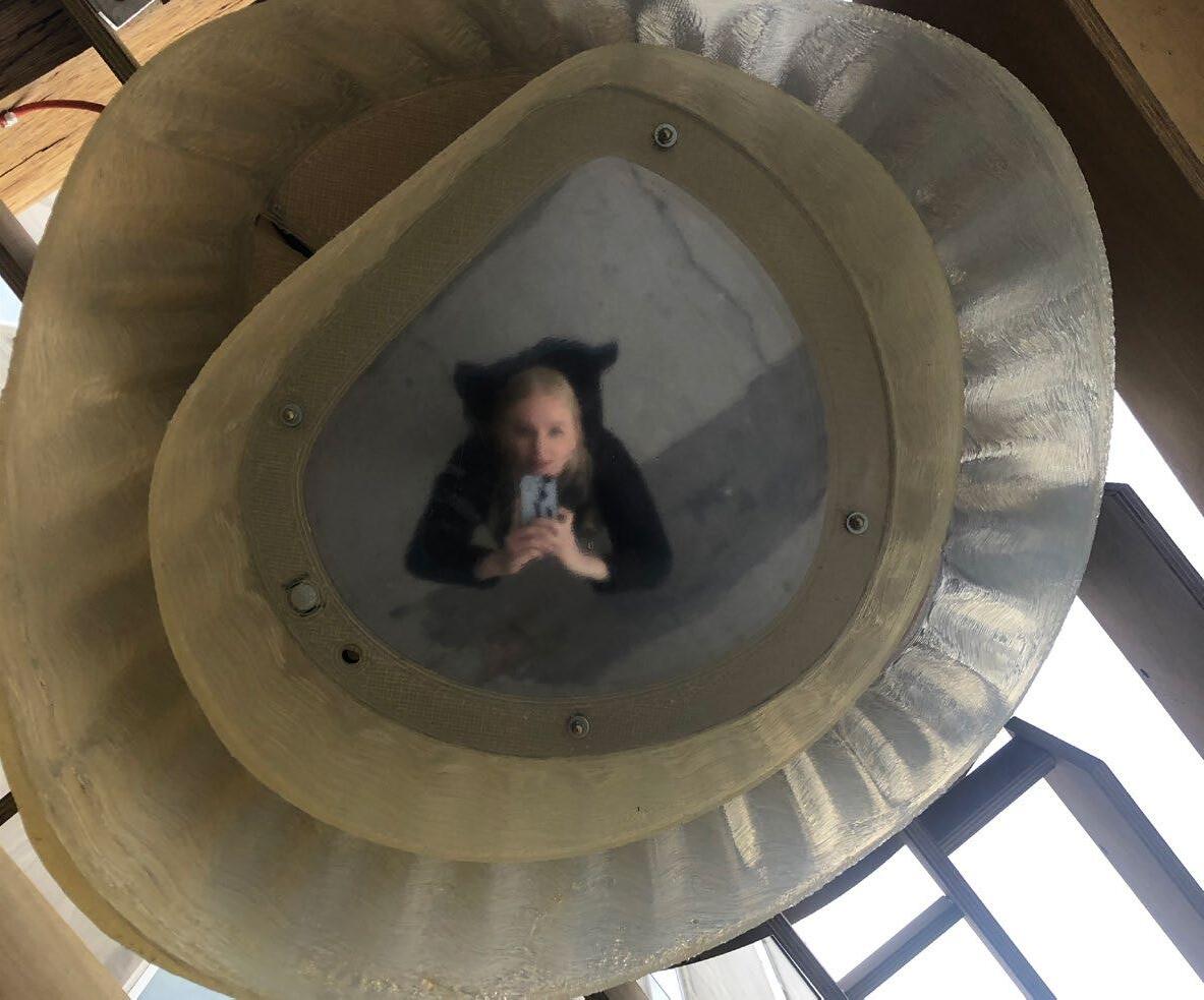
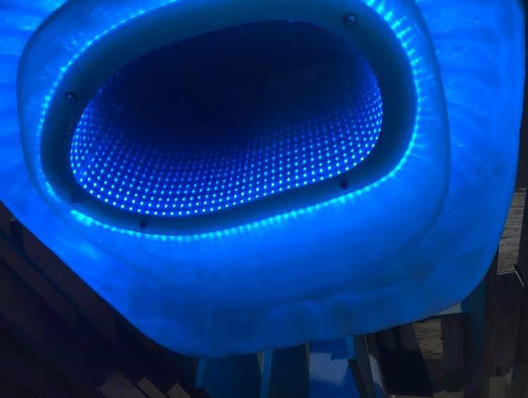
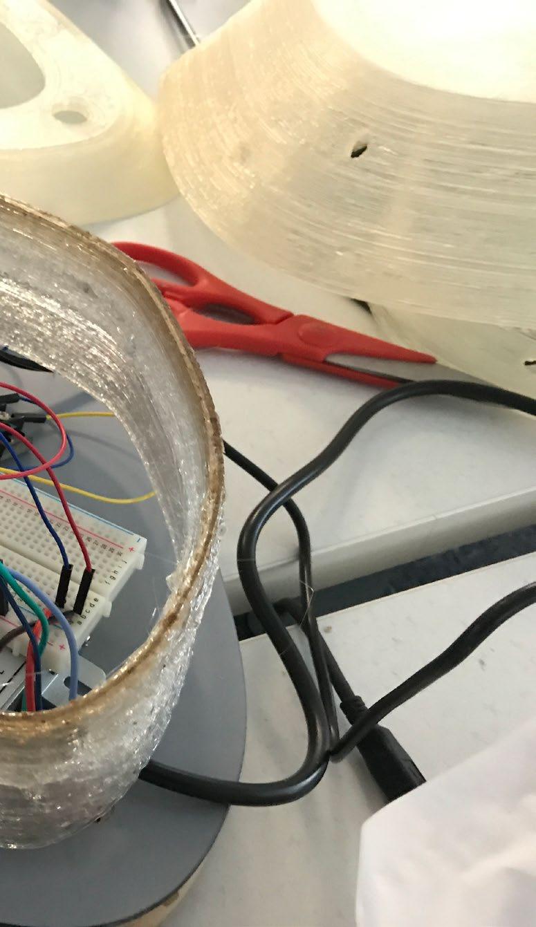
The light fixtures have been 3D printed at the SAPL’s City Building Design Lab using recycled plastic and contain sensors. So during night time, they will illuminate the sidewalk through the “infinity mirror“ and the linear LED strips underneath each layer of “shell“ when the sensors detect pedestrian’s movement below. This ensures people feel safe waiting for the bus at night. During the day when the LED’s are not on, the “infinity mirror“ turns into a one-way mirror, so pedestrians will see their own reflections in the mirrors.
One-way mirror effect during day time
Photo credit: Shelby Christensen
Infinity mirror effect at night time
9
Photo credit: Raye Liu
Nuts Nuts
Top Cover
Top Cover
Water-resistant MDF
Outer Shell and Housing
Outer Shell and Housing Space for Electronics (Arduino board, transformers etc.)
LED Strand
LED Strand Attached unto the Edge
Electronics
Electronics
Acrylic Mirror (one-way)
CNC Milled MDF Spacer
Acrylic Mirror Spacer
LED Strand
LED Strand along the Edge
Plexiglas with Two Way Mirror Film
Plexiglass with Two Way Mirrow Film (function as two-way mirror)
PIR Sensor
PIR Sensor
Inner Shell
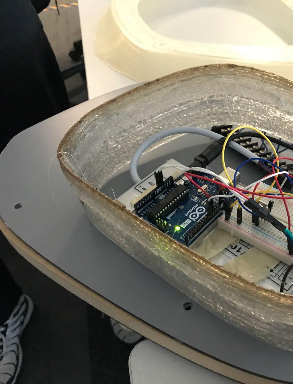
The electronics and transformer, programmed
LED Strand
LED Strand Attached along the Edge
Customized plastic Grasshopper
Threaded Rods
Nuts
Inner Shell Rods
Nuts
Light 14 (Large)
10 BUILT INSTALLATION
Light assembly axo
electronics compartment houses power cord transformer, and an arduino board that can be programmed through wifi connection to change colors of the LED strips in each lamp
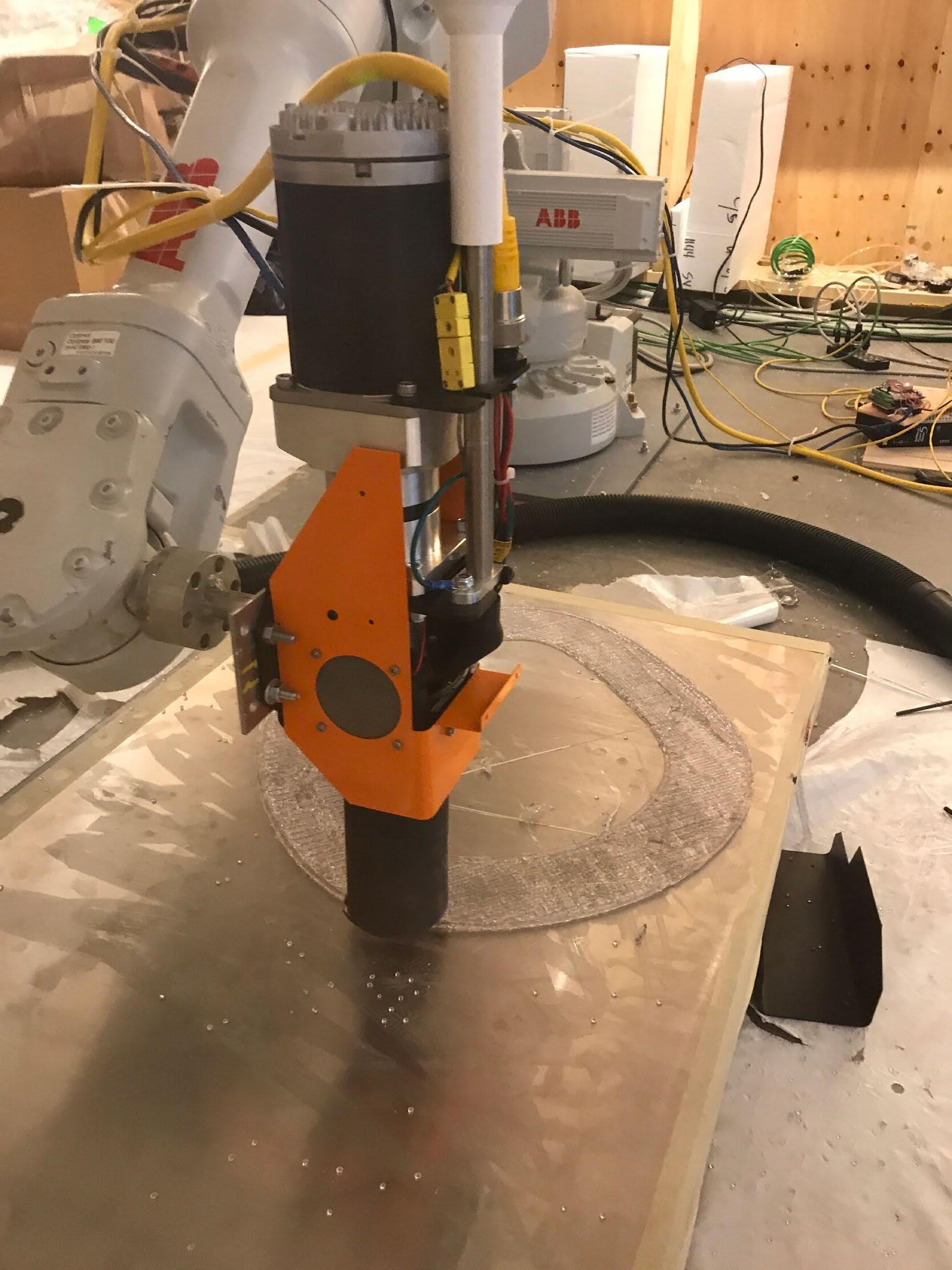
Customized robotic arm using granulized recycled plastic to 3D print the light parts directly through Grasshopper scriptting and Rhino 3D model
11
12 BUILT INSTALLATION
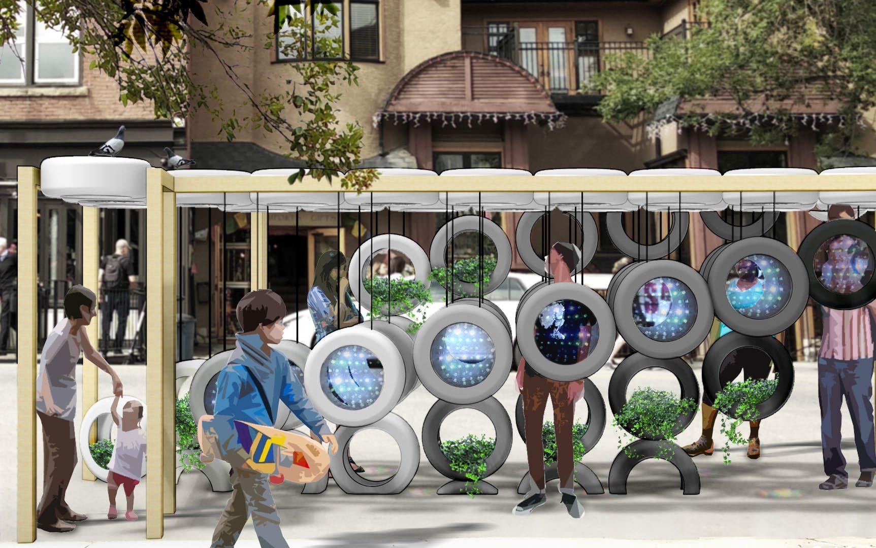
Rendering submitted for competition
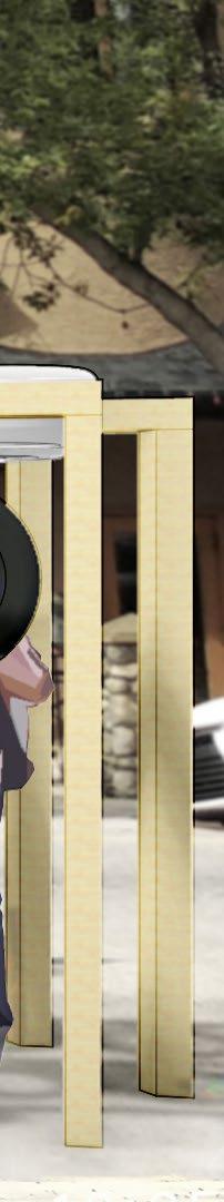
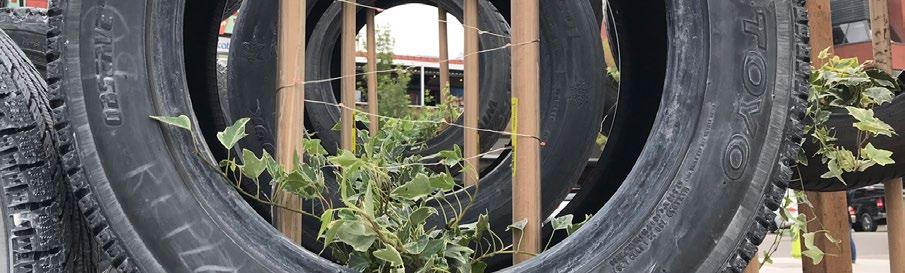
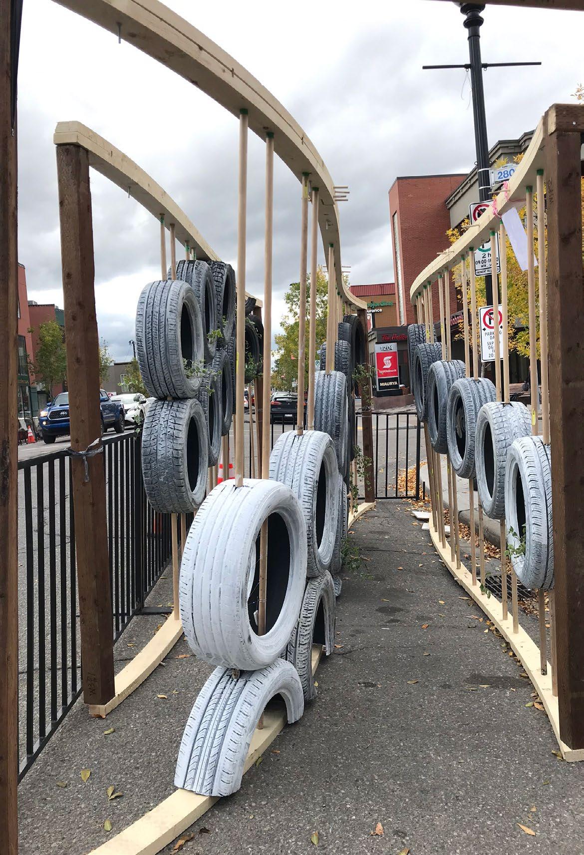
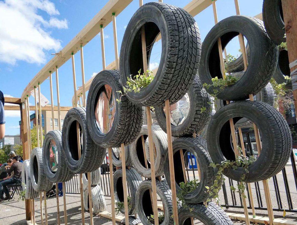
RE-TIRE
Built installation, exhibited on PARK(ing) Day 2019, Calgary
Dimension: 2.4 m (L) x 6 m (W) x 2 m (H) (two parking stalls)
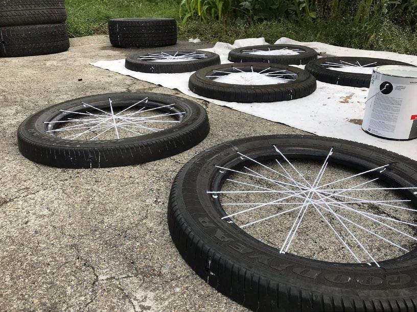
Materials: tires, paint, yarns, colored films, two-way mirror films, wood dowel pins, 2"x12" wood planks, metal hardware, LED lights, ivy planters
Team project
Team members and roles:
Team Lead: Raye Liu
Design Assistance: Judy Liu
Technical Support: Ji Yong Chyung
Graphics: Jason Park
Finance and Fundraising: Ryan Spring
Software: Rhino, Photoshop, Illustrator
Tools and Equipment: CNC machining and power tools during pre-fabrication, hand tools during installation insitu
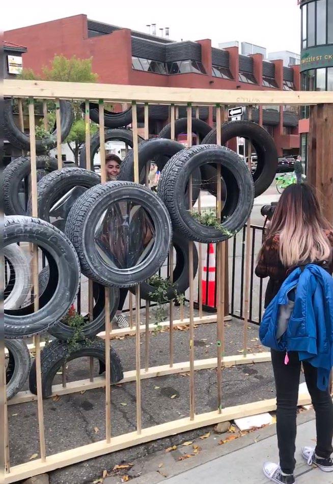
"Re-Tire" is a public-space intervention designed and built by a student team of five. It won the exhibition opportunity for PARK(ing) Day (September 20, 2019) in Calgary, Alberta, Canada, after the evaluation of the submissions conducted by the Alberta Association of Landscape Architects (AALA). Our team is one of the only two grant-winners among all the participants of the year. The installation of "Re-Tire" received media coverage before and after the event by the City of Calgary, the Avenue Calgary Magazine, University of Calgary and AALA.
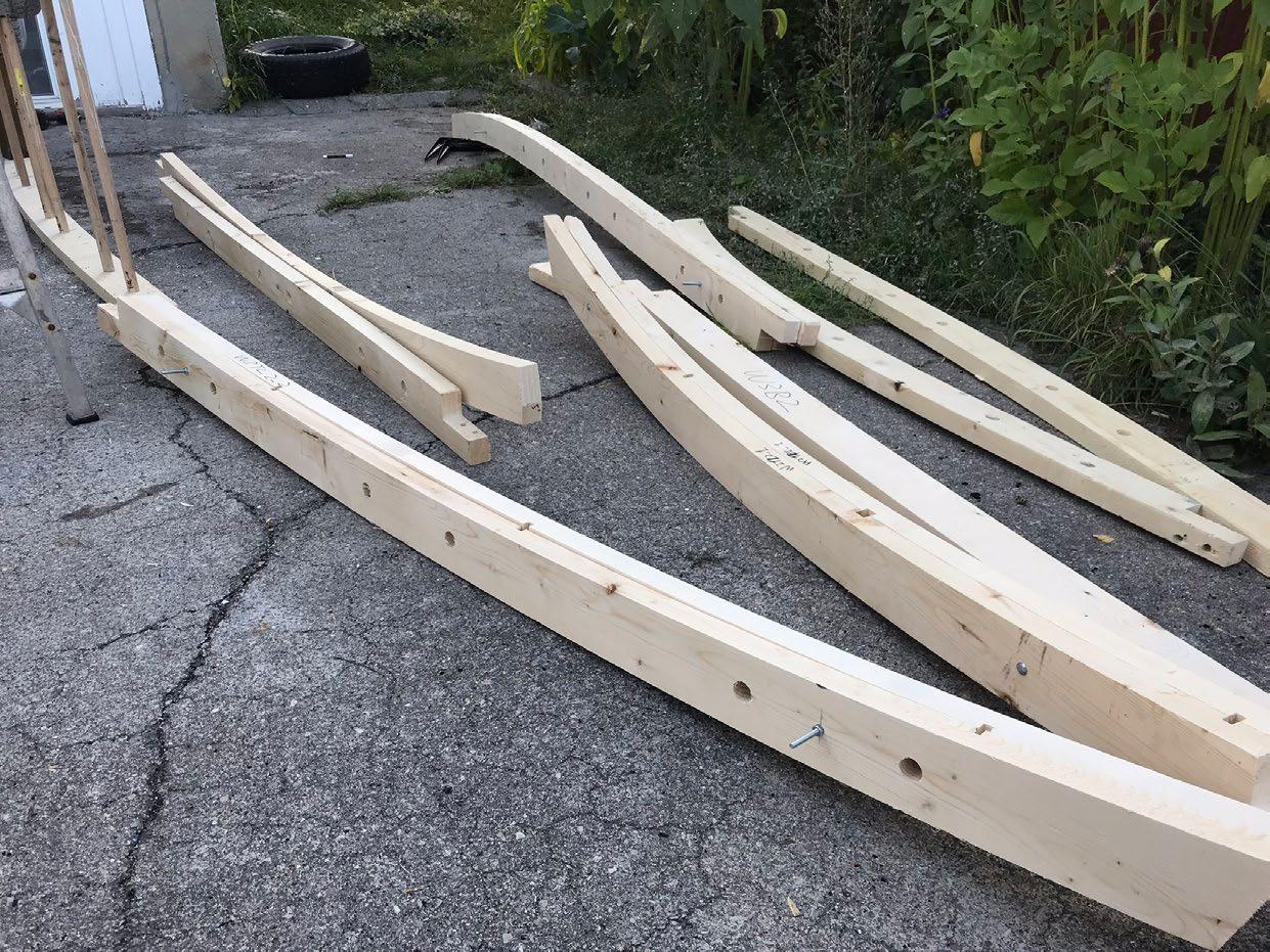
"Re-Tire" advocates environmental sustainability by upcycling used car tires and curates a space to interact with people of all ages. There is a pathway within the installation for visitors to walk through and enjoy the different visuals each tire has to provide. The whole structure is pre-fabricated off-site, and transported by truck on the installation day. The assemblies are put together sequentially according to how they are numbered.
13
14 BUILT INSTALLATION
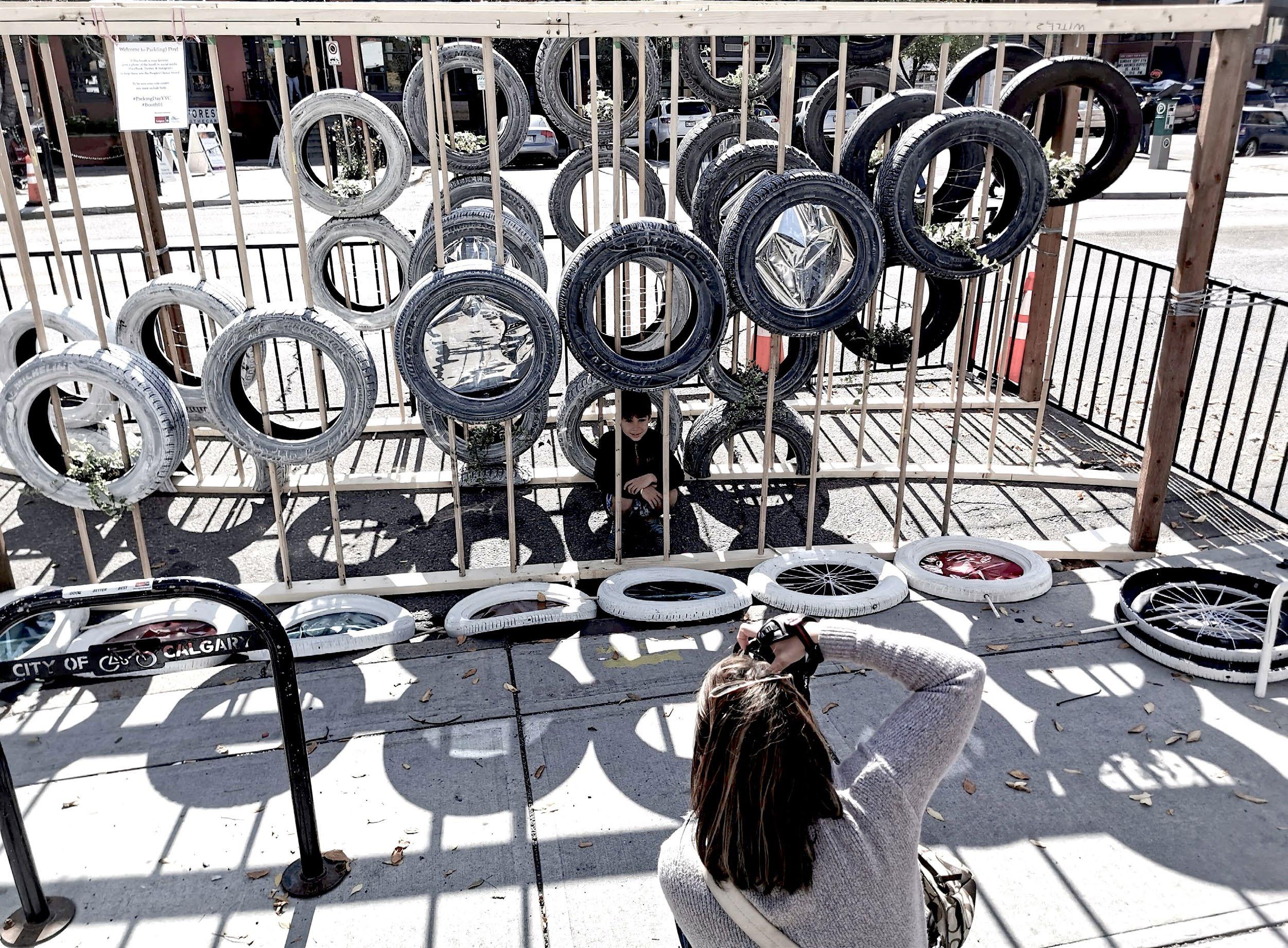
The internal pathway within the installation Friends and families appreciating the fun interaction "Re-Tire" creates and taking photos of each other
15
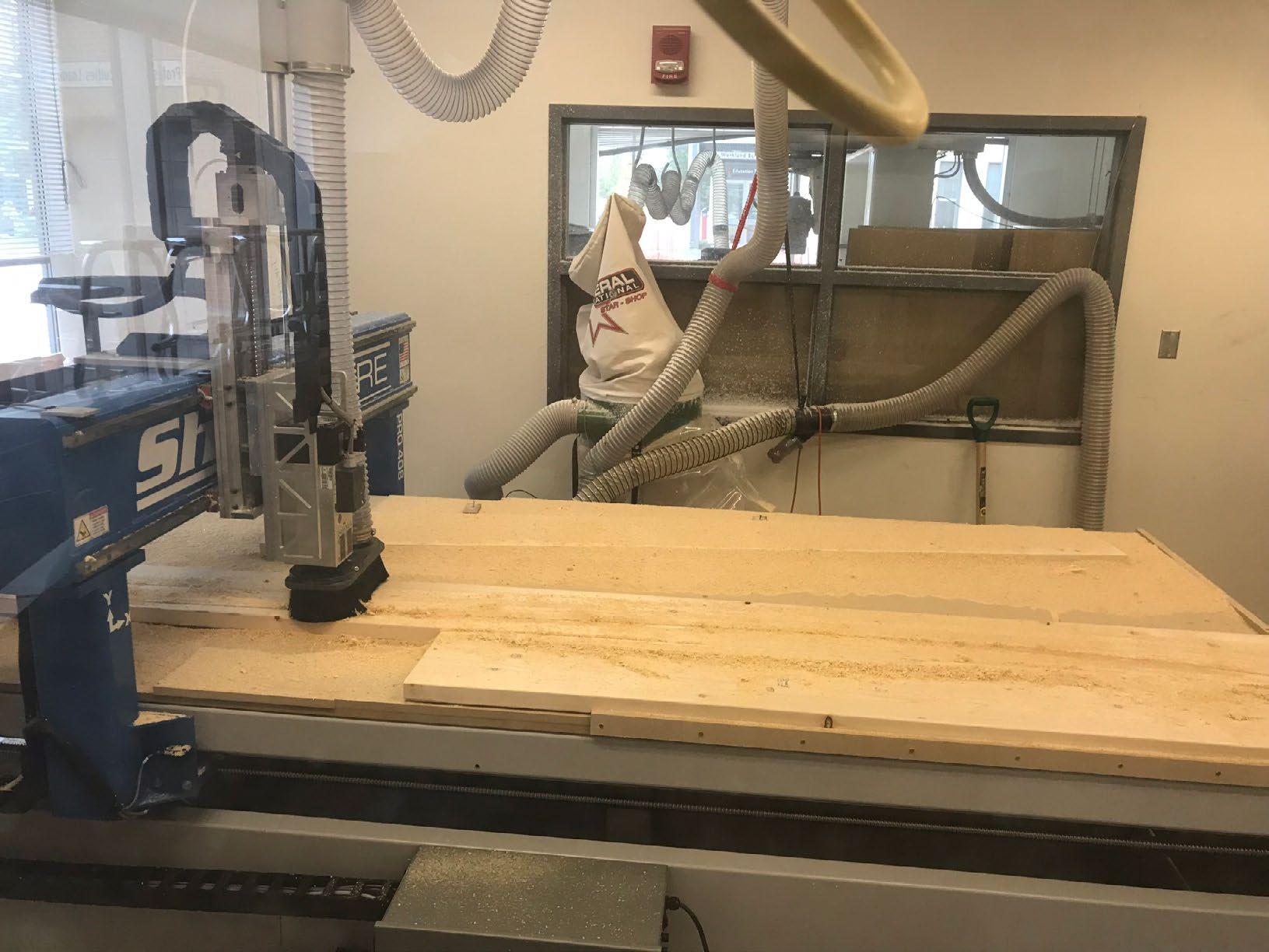
The top and bottom plates are manufactured through CNC using 3D models created in Rhino directly; double plates are bolted together for stability and depth to secure the vertical dowels
16
ASSEMBLY 6
ASSEMBLY 5
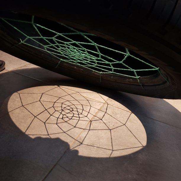
Experiments with weaving through half tires and their shadow effects. Those half tires were design to be installed as the "roof" of the stallation, which was not realized on the installation day
ASSEMBLY 4
ASSEMBLY 3
ASSEMBLY 2
ASSEMBLY 1
17
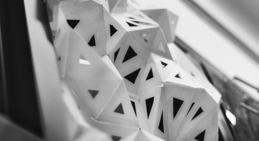
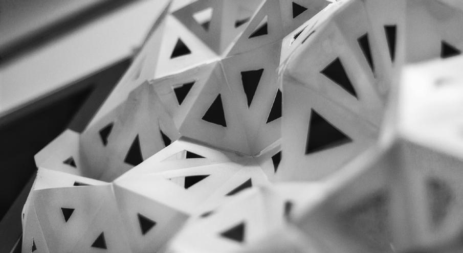
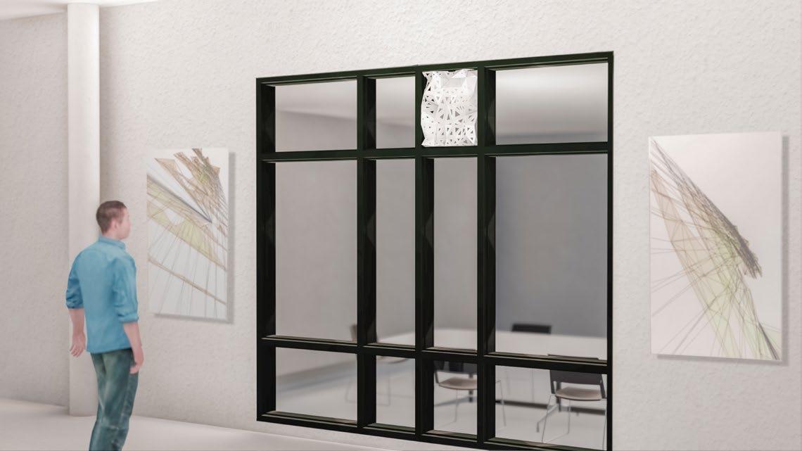
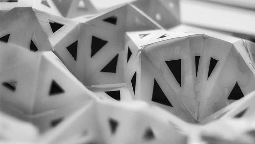
FOLDING LIGHT
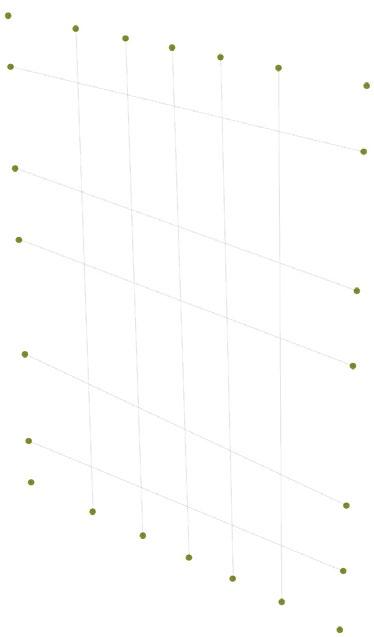
1. Points on grid
2. Locate points at curves' intersections; add randomized points
Tool: Rhino, Grasshopper
Team Project: John Rivera, Raye Liu, Zhengshi Lu, Rajbir Dhaliwal, Eric Sloan
Personal Contribution: conceptualization, coding, drafting, physical production
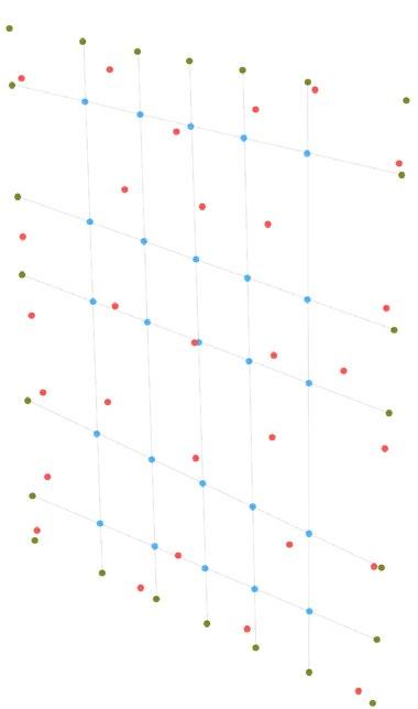
G2
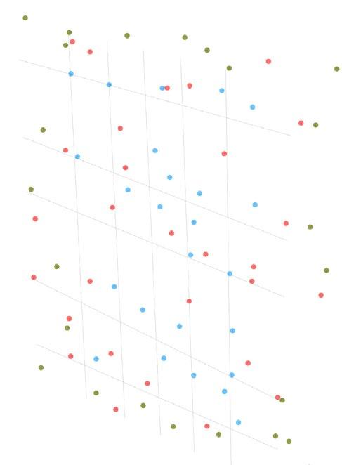
3. Merge all points and randomiz on Y-axis within 0 - 100 mm domain range to create depth
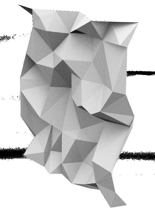
4. All points are connected through the Delaunay mesh component in Grasshopper to create a mesh
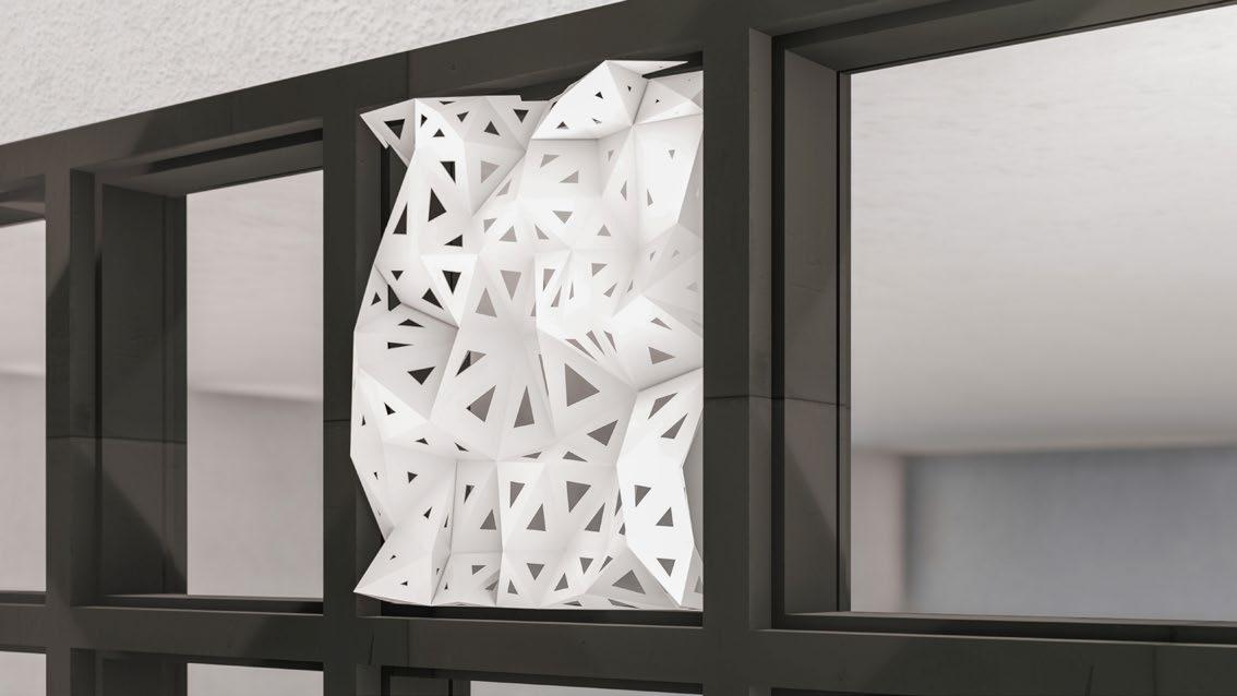
Render
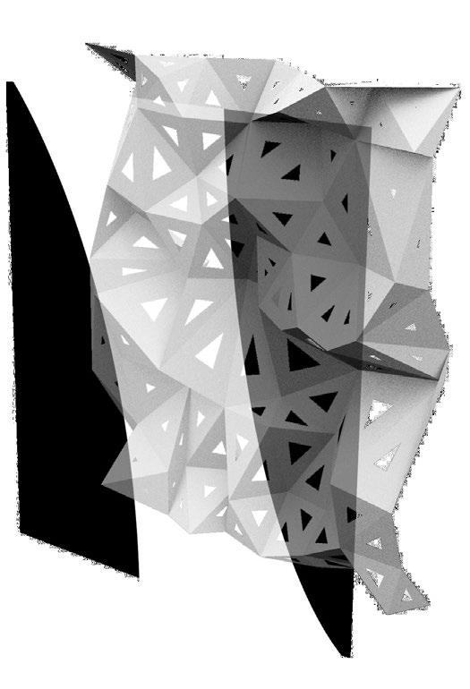
5. Scale of triangle becomes larger and triangles rotate to maximum 10 degrees in the white zone
Scale of triangle becomes smaller and triangles do not rotate in the black zone
RENDERING 2 CLOSE-UP VIEW
G3
Render
RENDERING 1 OVERALL VIEW
18 BUILT INSTALLATION

Front Elevation
The screen is composed of 12 unrolled pieces, colorcoded as above.
Side Elevation


Typical detail
1 2 3 4 5 9 6 10 7 11 8 12
Plan Unrolled Piece No. 1
4"
1'-4 7/8"
2
3" 5
Fold inward Fold outward 1/5"
Matt
19
1'-8 7/8" 3/8"
1/8" 1'-5 3/8"
5/8"
thick polysheet
white spray paint on both sides Photos after Installation
20 LANDSCAPE ARCHITECTURE DESIGN
POUNCE
Academic (2020)
Individual project
Conceptual Design
Project Area: 1,567 m2
Function: Cultural , Recreational
Software: Rhino, Grasshopper, Photoshop
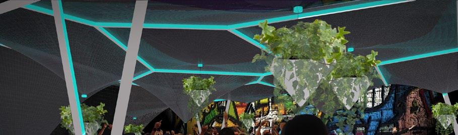
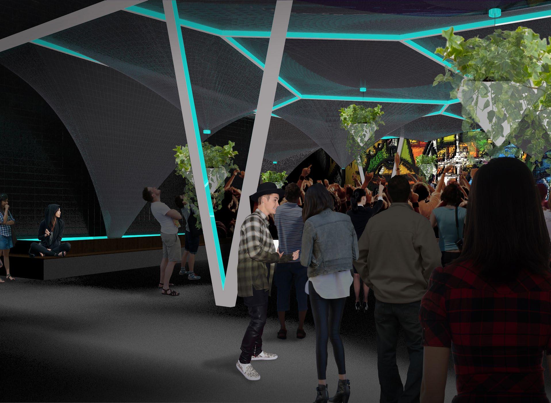
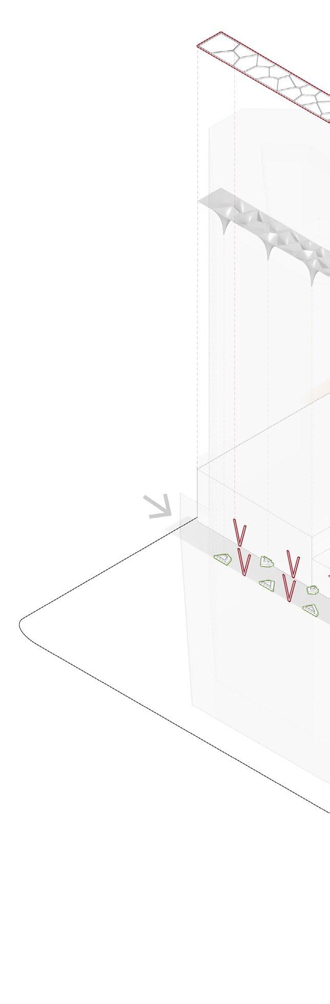
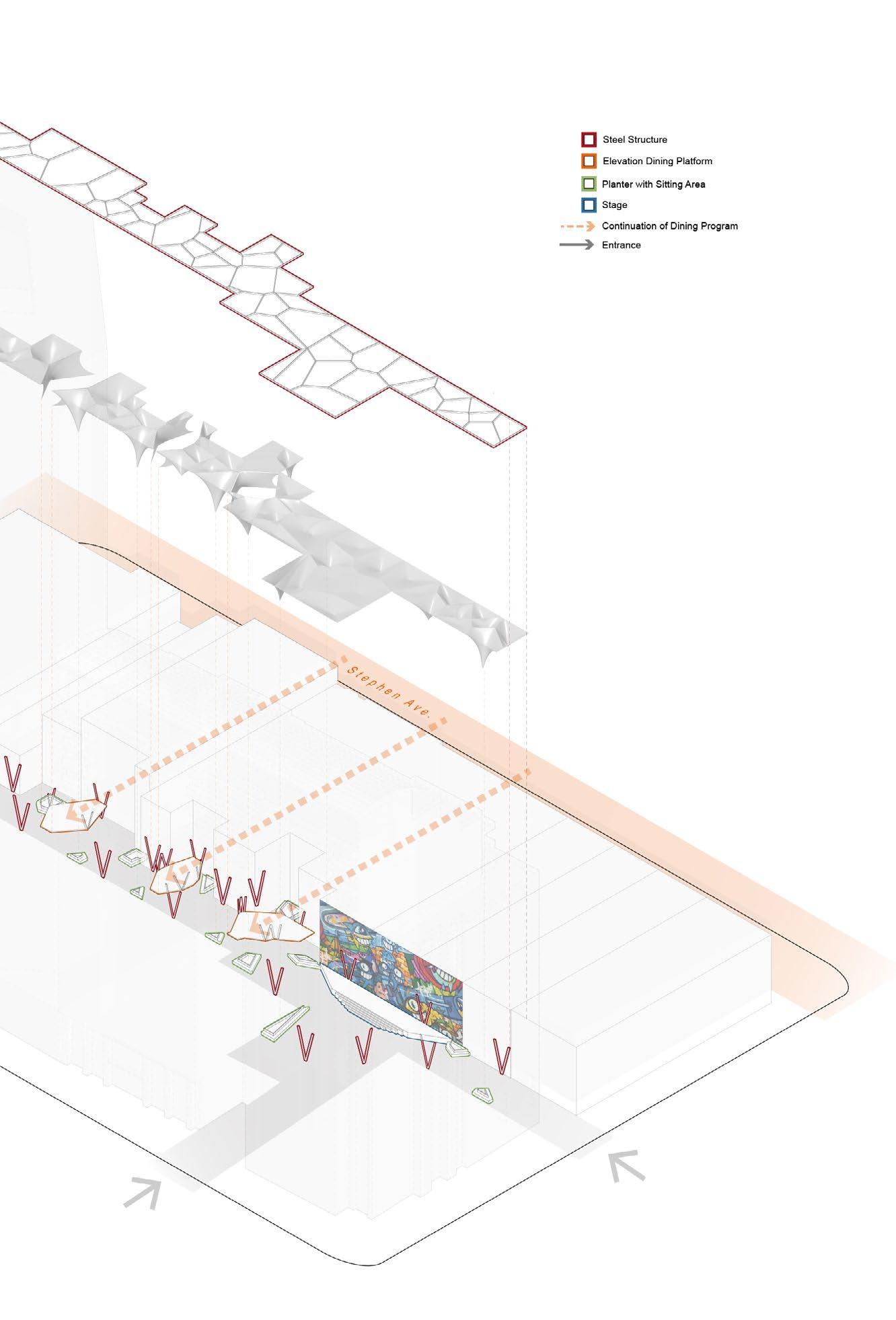
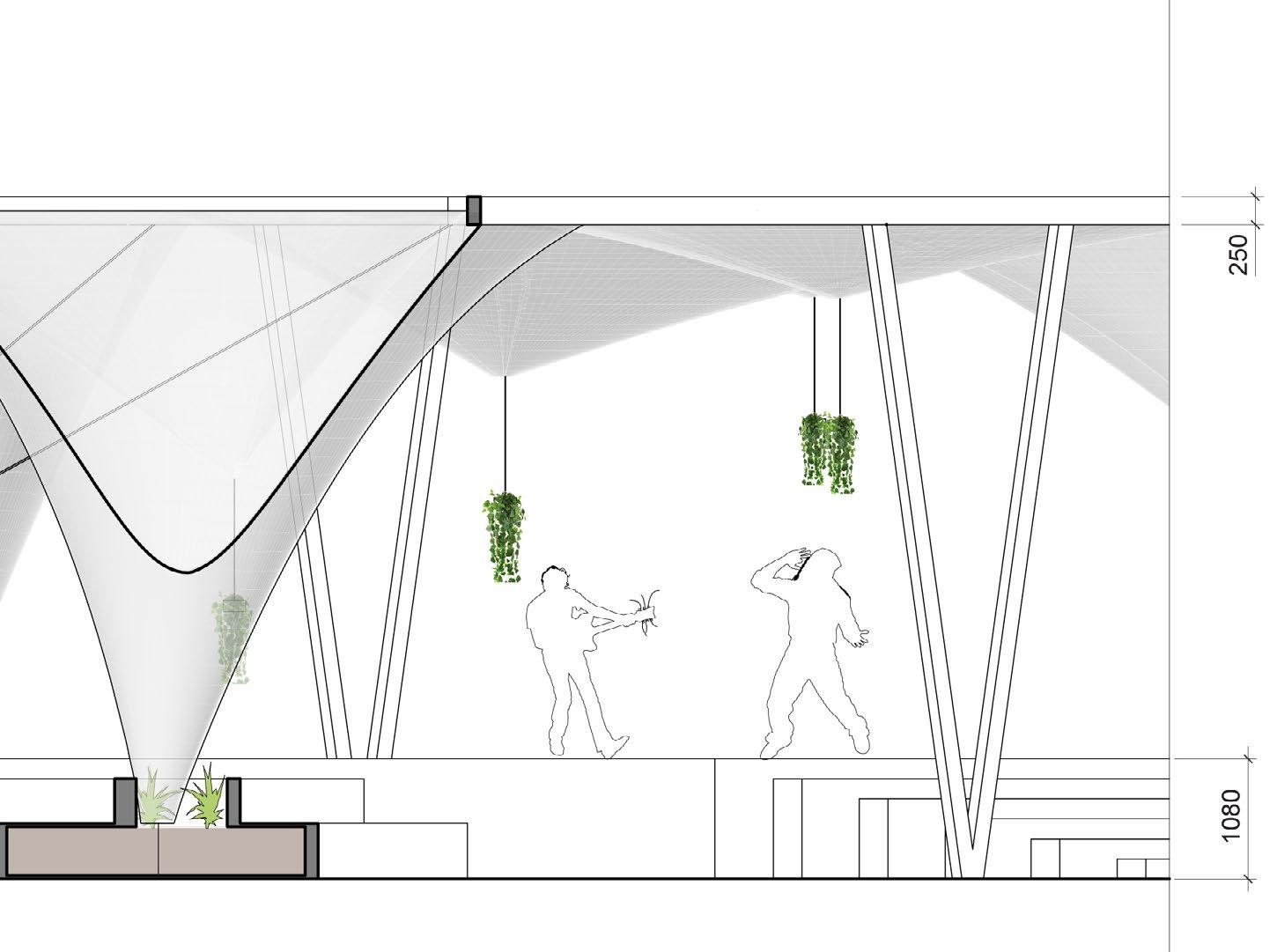
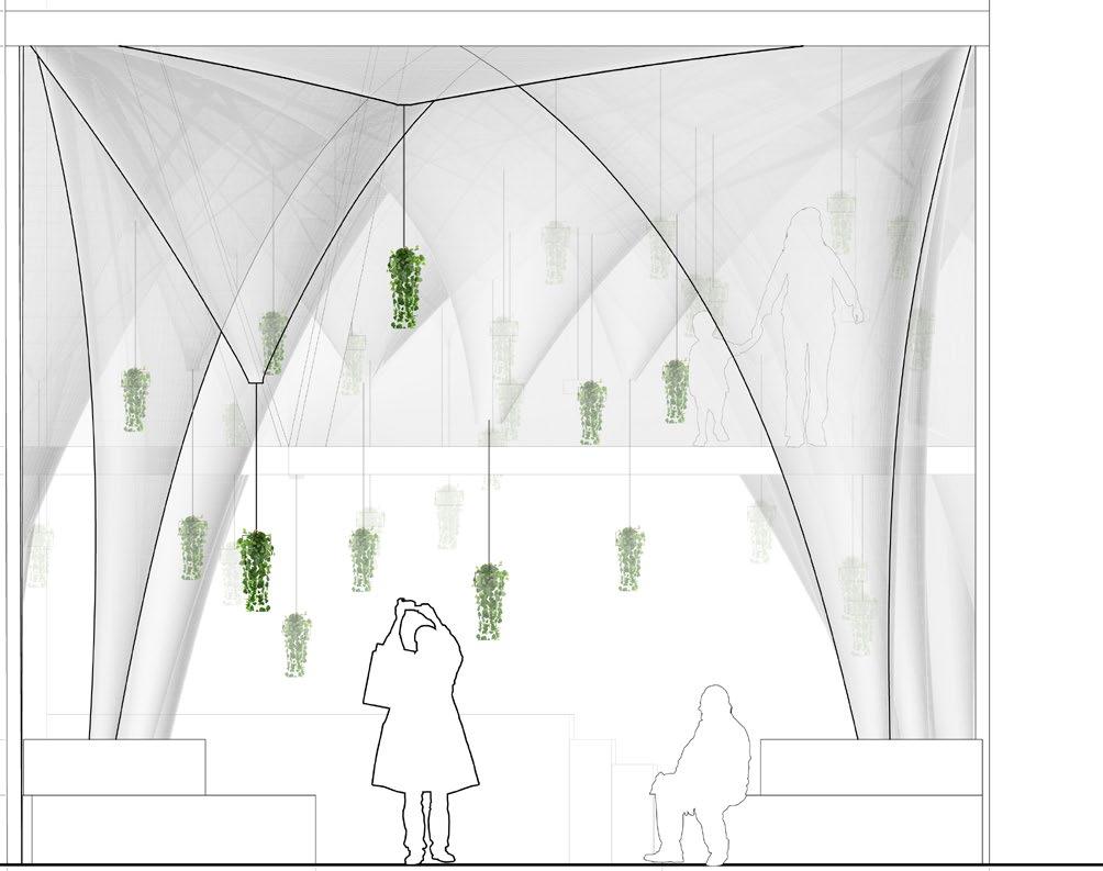
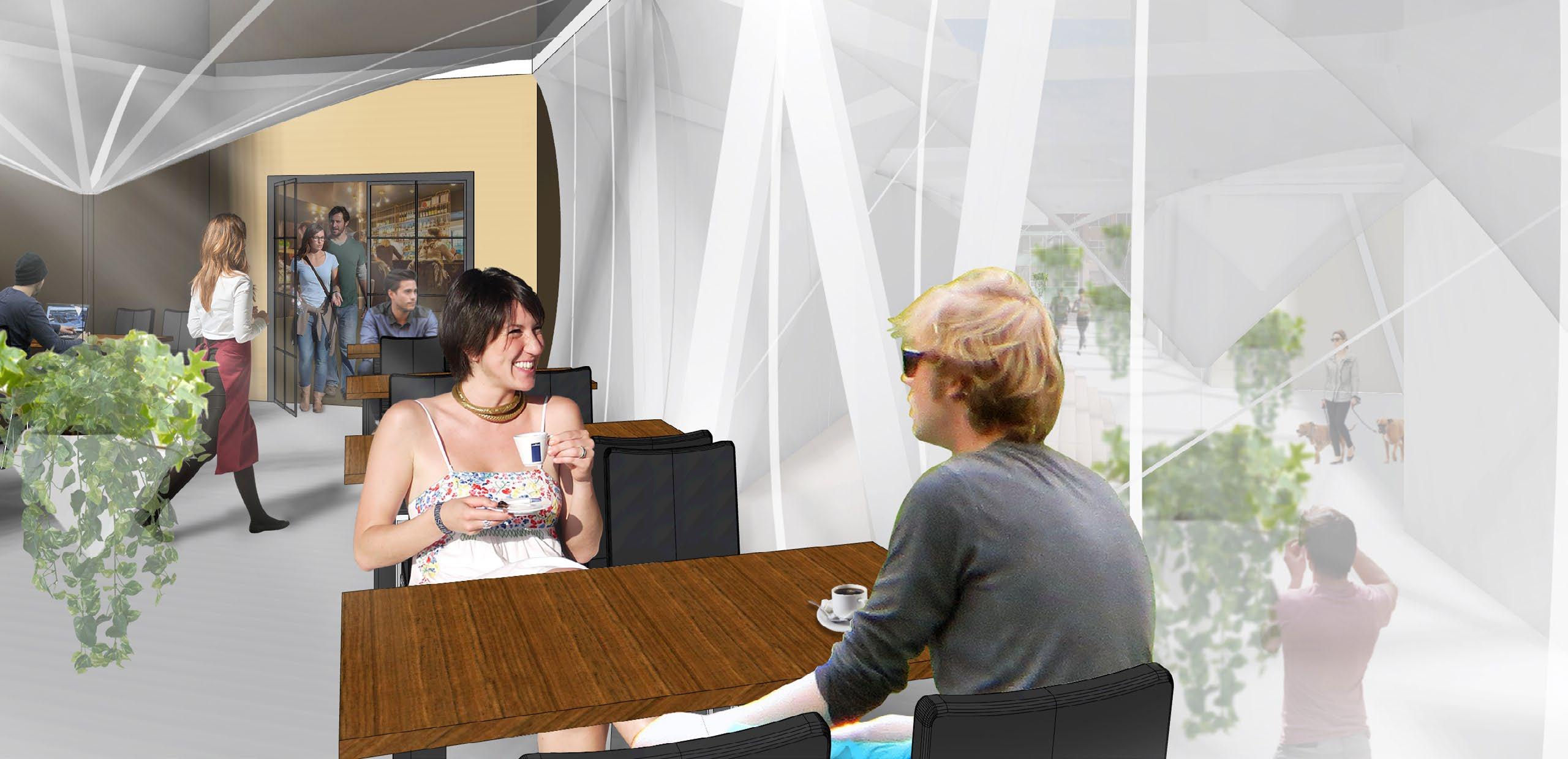
The project “Pounce“ is a tensile fabric structure to activate the back alley between buildings sitting along 8 Ave (Stephen Ave) and 9 Ave, Calgary.
Considering the currently dominant dining program along 8 Ave, the project intends to let the dining services overflow into the back alley, to serve the nine-tofive office workers and hotel dwellers along 9 Ave within a minimized walk distance.
While dining on those elevated platforms, people also have the opportunity to enjoy the landscape along the alley.
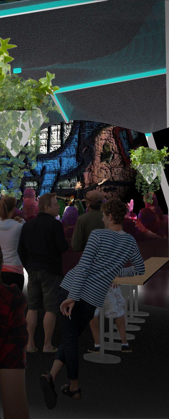
Another intention is to maximize the landscape influence the current graffiti wall can exert at the south entrance. Functioning as a beacon for fun and vibrancy during both daytime and night, the graffiti wall now works as a backdrop for the semi-outdoor stage. Hopefully, through a re-arrangement of programs and refinement of landscape details, the project will be an attraction point, especially for the younger generation.
21
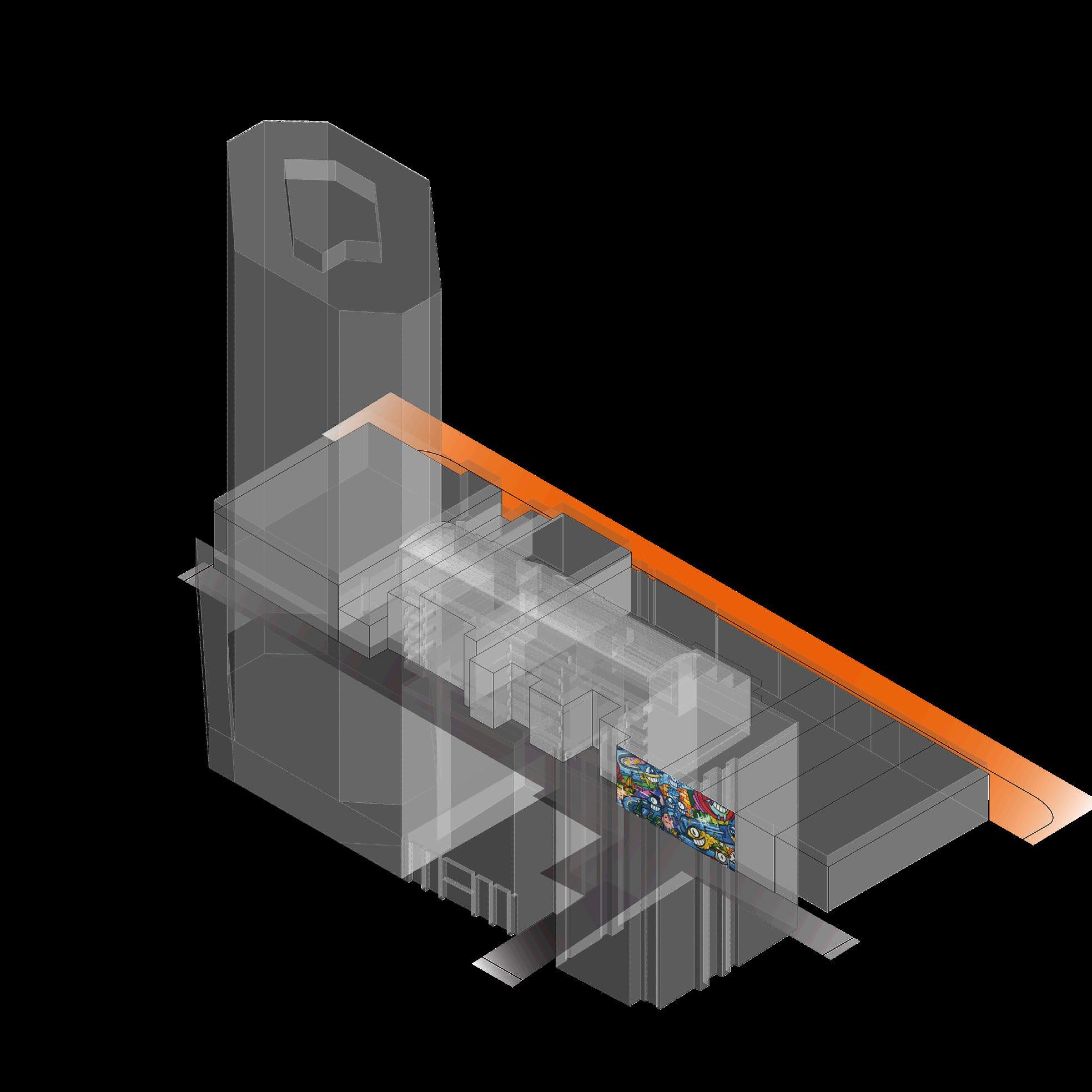
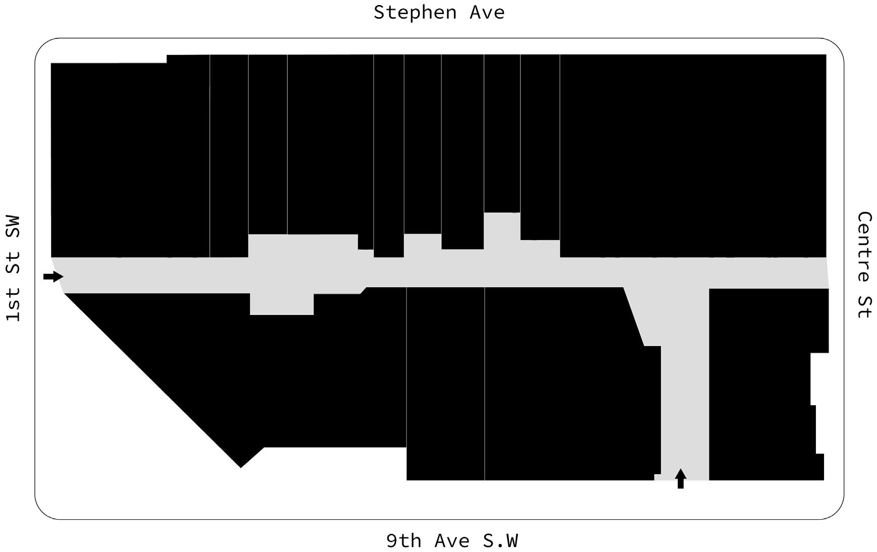
The existing condition: the back alley has three entrances - two at each end and the third is a crossthrough on the ground level under a high-rise, which also expose the graffiti wall when people passby on the main road
22 LANDSCAPE ARCHITECTURE DESIGN
PO NCE
Steel Edge Beams
INDEX
Site Analysis
Zoning Program Details
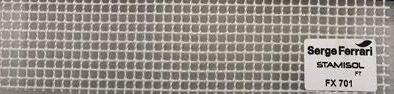
Tensil Fabric
Intention:
PO NCE tensile membrane structure
INDEX
Site Analysis
tensile membrane structure
Zoning Program
Details
• Dining & entertainment
• Increase greenery area
• Night life
Elevated Dining Platforms on 2nd Floor
Steel Frame Hanging Elevated Platform
Dining
Graffiti Wall
Island Planter Seat
Entertainment
Greenery
Graffiti Mural
Intention:
• Dining & entertainment
• Increase greenery area
• Night life

Dining Entertainment
Dining Entertainment
Greenery
Green Spaces
Graffiti Backdrop
Graffiti Mural
Proposal: extend the dinning program in the storefronts on Stephen Avenue all the way to the back alley. Use the back alley as an outdoor dining environment. Build a stage using the graffiti wall as the backdrop, creating an amphitheatre for entertainment events. Island planters on the ground level function also as anchors for the tensil membrane structrue that provides a certain degree of protection from the environment.
23
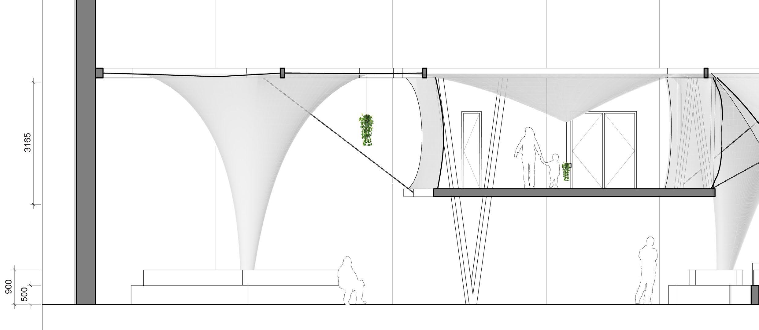
3720 17221 7050 2455 Section Ground Level Floor Plan 24 LANDSCAPE ARCHITECTURE DESIGN
7571 3720 17221 7571
25
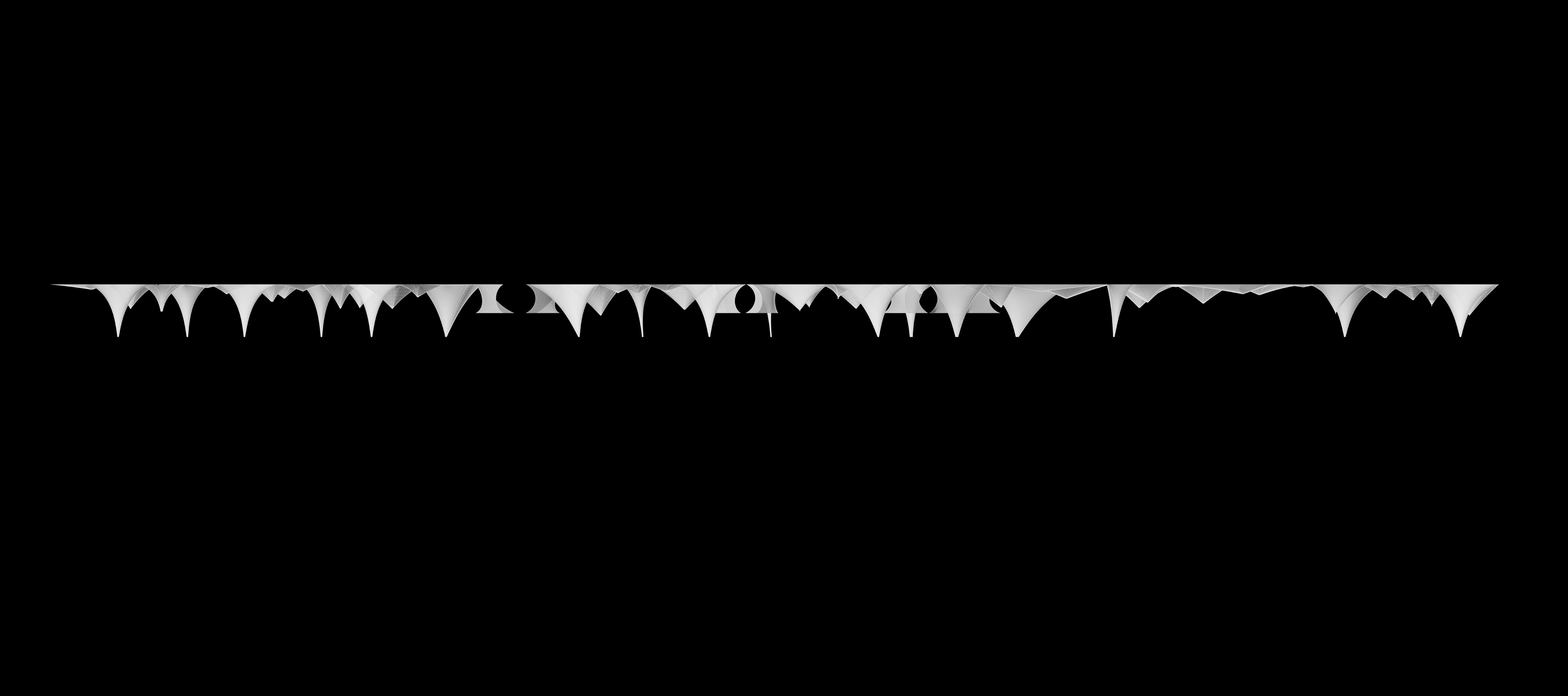
Short Elevation
2nd Level Floor Plan

Inner Clamping Ring
Turnbuckle
PRODUCED BY AN
Detail: Hanging Planter System and Low-Point Ring
Outer Clamping Ring
Cage Holding Planters

BY AN AUTODESK STUDENT VERSION
PRODUCED
AUTODESK STUDENT VERSION
AUTODESK STUDENT VERSION
PRODUCED BY AN
26
LANDSCAPE ARCHITECTURE DESIGN
27
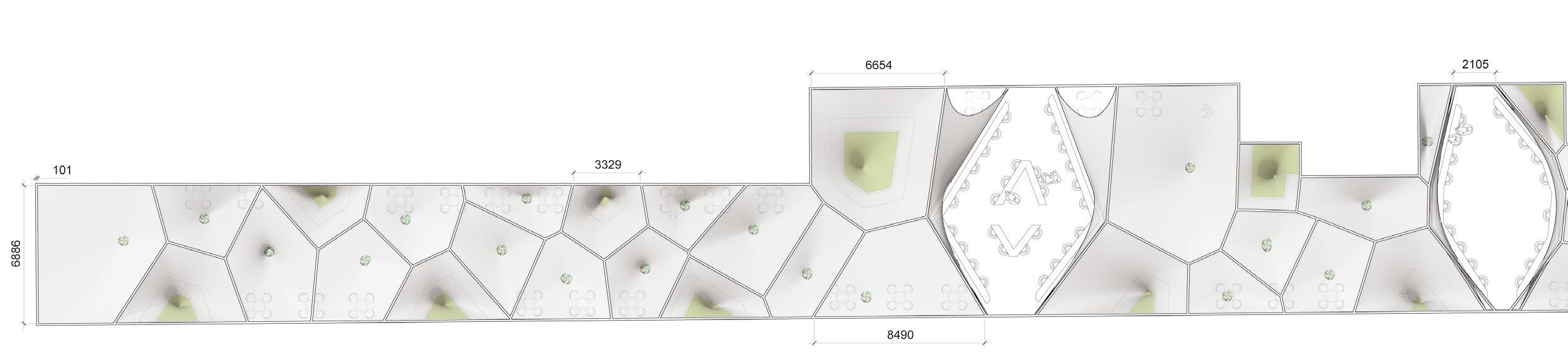
Roof Plan
PRODUCED BY AN AUTODESK STUDENT VERSION
Self-tapping Screw Clamping Plate
Wrapped Kedar Inside Fabric
Detail: Rigid Edge


BY AN AUTODESK STUDENT VERSION
PRODUCED
AUTODESK
BY AN AUTODESK STUDENT VERSION
PRODUCED BY AN
PRODUCED
Longitudinal Elevation
28 LANDSCAPE ARCHITECTURE DESIGN

Clamping Plate Self-tapping Screw
Fabric Kedar
Edge Beam Pin Connection
Sectional Detail: Rigid Edge Beam
Detail: V-Frame Footing & Connection
STUDENT VERSION 2800 5875 1080 500
AUTODESK STUDENT VERSION
AUTODESK STUDENT VERSION PRODUCED BY AN AUTODESK STUDENT VERSION
AUTODESK STUDENT VERSION
AN AUTODESK STUDENT VERSION
AN AUTODESK STUDENT VERSION PRODUCED BY AN AUTODESK STUDENT VERSION
BY AN AUTODESK STUDENT VERSION
PRODUCED BY AN
PRODUCED BY AN
PRODUCED BY AN
PRODUCED BY
PRODUCED BY
PRODUCED
29
COLLIDE
Academic (2020)
Individual project
Conceptual Design
Project Area: 6,156 m2
Function: Cultural , Recreational
Software: Rhino, Enscape, Photoshop
30 ARCHITECTURE DESIGN
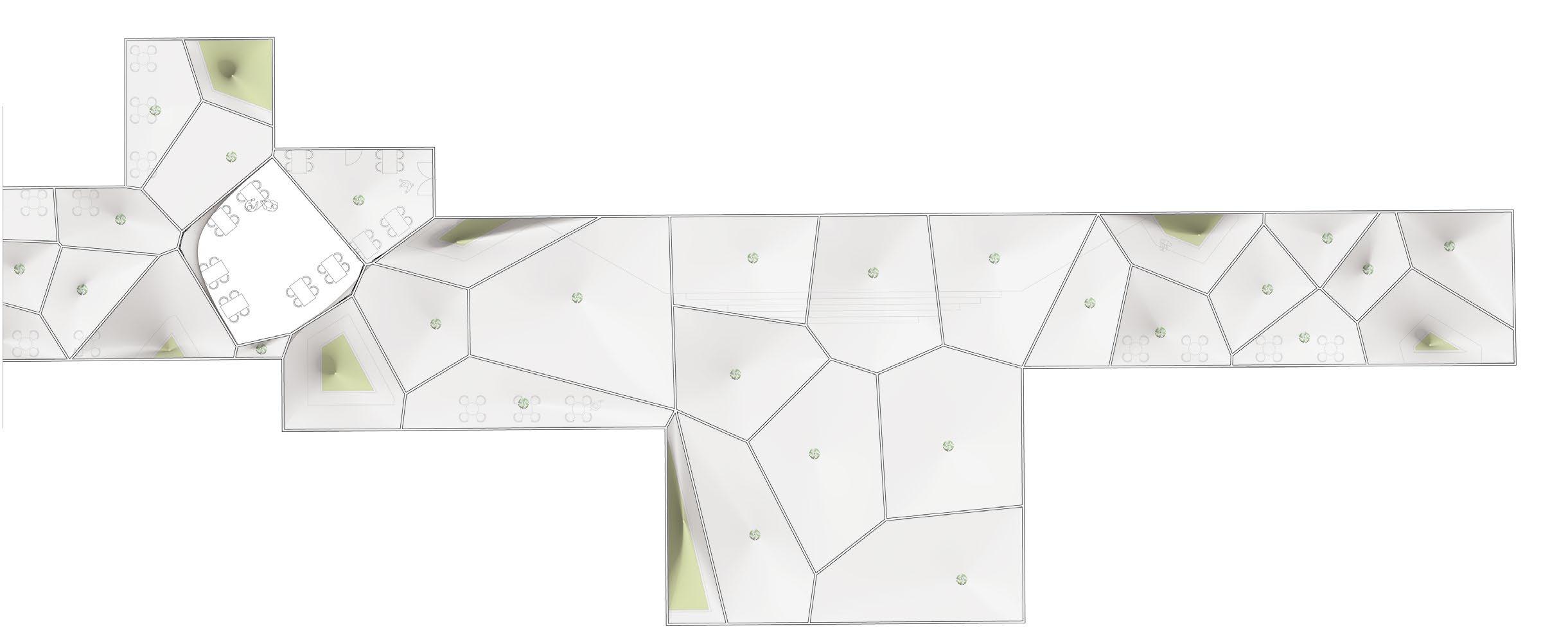
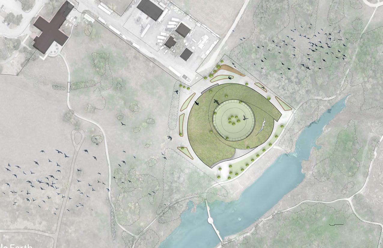
Journey of the Bird Sanctuary
Journey of the Linear and Circular Architecture
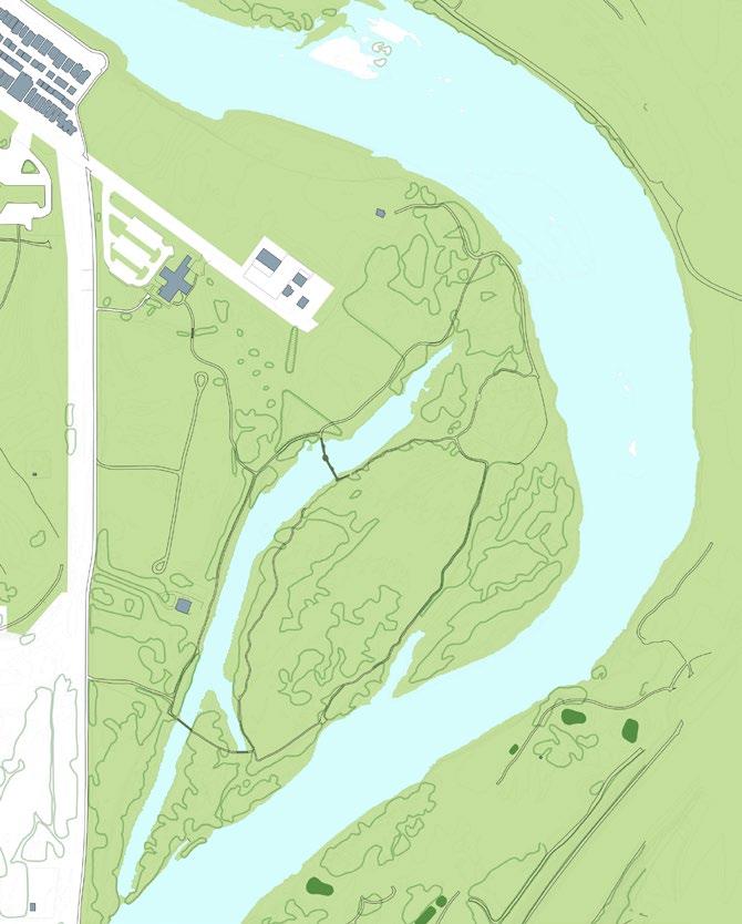
The site is the breath-taking Inglewood Bird Sanctuary situated along the Bow River in Calgary, Alberta. The curated bird-watching journey is a loop that starts and ends at the existing parking lot. To correspond with the curated linear journey, the architecture naturally is designed as a “loop within a loop“.
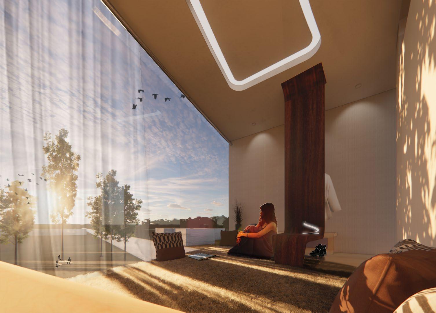
By the time of this design exercise, it was in the middle of the heated discussion about mental health issues that are brought about by COVID situation. Thus this project is also a review about how architecture can contribute to the mental health of the users. Based on the belief that a multi-modal program is beneficial to activate the different areas of the human brain, Collide is a recreational project that incorporated all different modalities and supra-modalities - as a collision of programs through various spatial heights and elevations, visual connections and adjacency to biophilia.
31
1. CAFE
2. BOOKSTORE
3. COUNSELLING
4. BREAKOUT ROOMS
5. PERFORMANCE ART
6. EXHIBITION
7. ART EDUCATION / MAKERS’ SPACE
8. ART & DESIGN STUDIO
9. MUSIC STUDIO
10. MIND-BODY WORKOUT
11. BOXING
12. SUNKEN GARDEN
13. ROCK CLIMBING
14. MEDITATION / PRAYER ROOMS
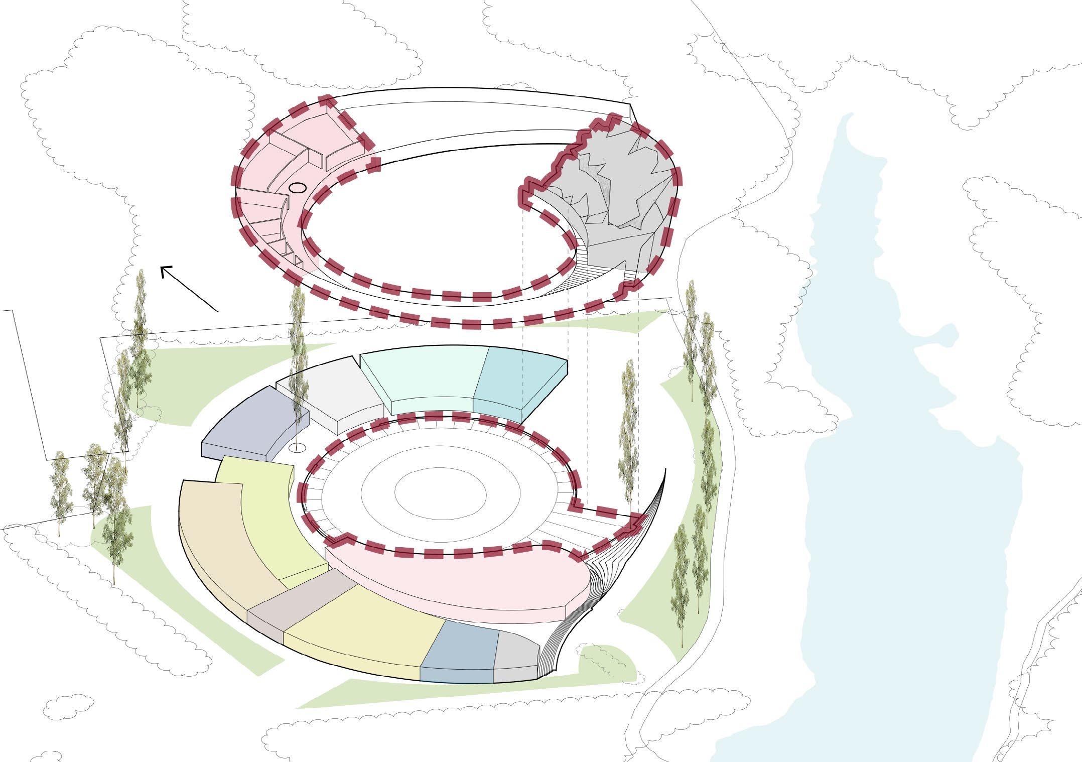
N 1 ENTER LOGISTICAL ACCESS POINT (BOH) FOCAL AREA +-0 -1.5 M -1.5 M -1.5 M +6 M
2 3 4 6 7 8 9 10 11 12 13 14 5 32
ARCHITECTURE DESIGN
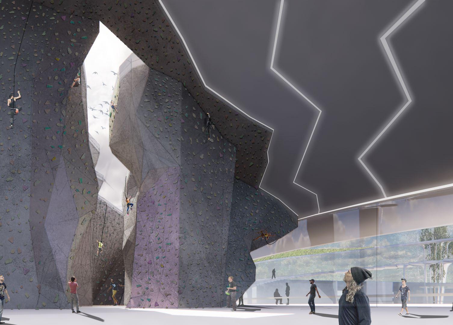
Climbing Space 33
Rock
34
DESIGN
Meditation Room on the Second Level
ARCHITECTURE
+6 M
GROUND
-1.5 M
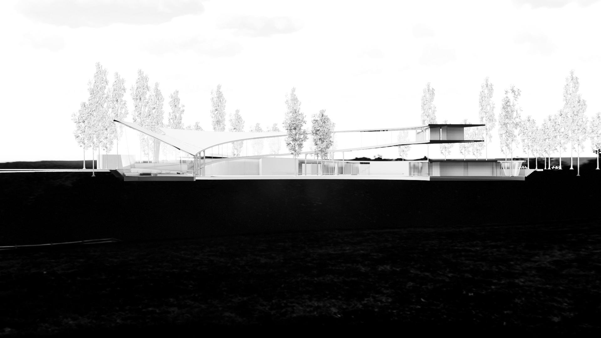
OPEN CAFE & CASUAL SEATING NEAR EXIT
TRAIL & PUBLIC ENTRANCE
MEDITATION SPACE
ROCK CLIMBING
OPEN STAGE
BOH ENTRANCE FROM 9 AVE
ENTRANCE TO THE BUILDING
ART EDUCATION CLASSROOM
COUNSELLING CENTRE MEETING ROOM
COUNSELLOR OFFICE
THEATRE PERFORMANCE ART STUDIO
KICK BOXING STUDIO
ENTRANCE TO GARDEN
35
36 ARCHITECTURE DESIGN
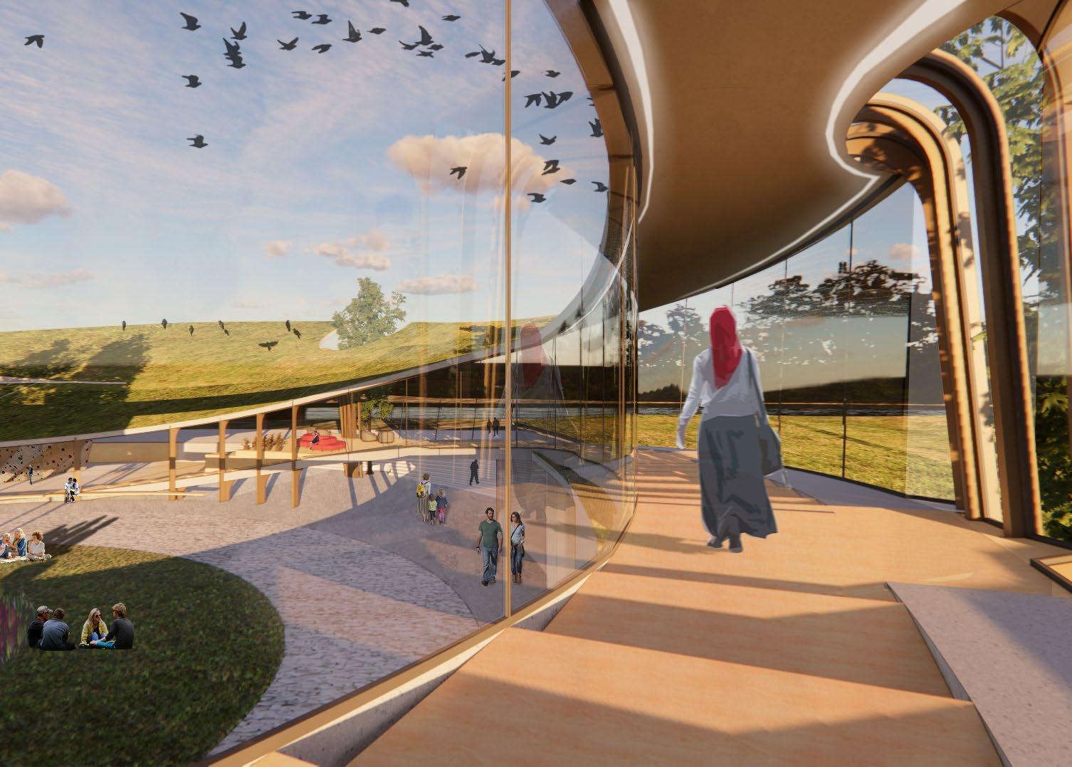
Outdoor Landscape and the Visual Connection with the Indoor
37
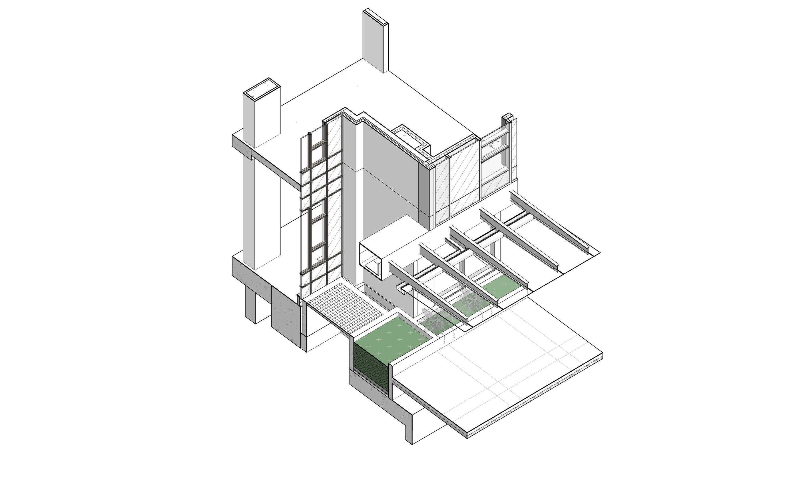
ALUMINUM CLADDING WHITE FINISH
100 MM RIGID INSULATION
WATER / VAPOUR BARRIER TO WRAP AROUND EXT. GRADE DRYWALL
EXT. GRADE DRYWALL
HAT CHANNEL SCREWED ONTO HSS
HSS - SEE STRUCTURAL DWGS
SLOPE DOWN TO GUTTER 3%
GUTTER BEYOND
SLOPE DOWN TO PIPE 2% MIN.
100 MM STEEL STUD
150 MM STEEL STUD
150 MM RIGID INSULATION
PIPE TO RAINWATER LEADER
OPEN TO PLANTER BELOW
Building Canopy Detailing 1: Exterior Condition
A A
38
TECHNICAL DESIGN
CAMBIE GARDEN PARCEL
CRole:
Coordinate engineering disciplines during Design Development phase;
Produce construction documents set, including envelop detailing;
Assist in the communication and clarification with the City during permitting process
Attend and write meeting minutes during consultant meetings
Location: Vancouver, BC
Construction documentation phase (2023present)
Project Type: New Construction
Gross Floor Area: 369,148 SF
No. of Stories: 28
Budget: CAD$60,000,000
Occupancy: Residential, Office, Healthcare
Software: Revit
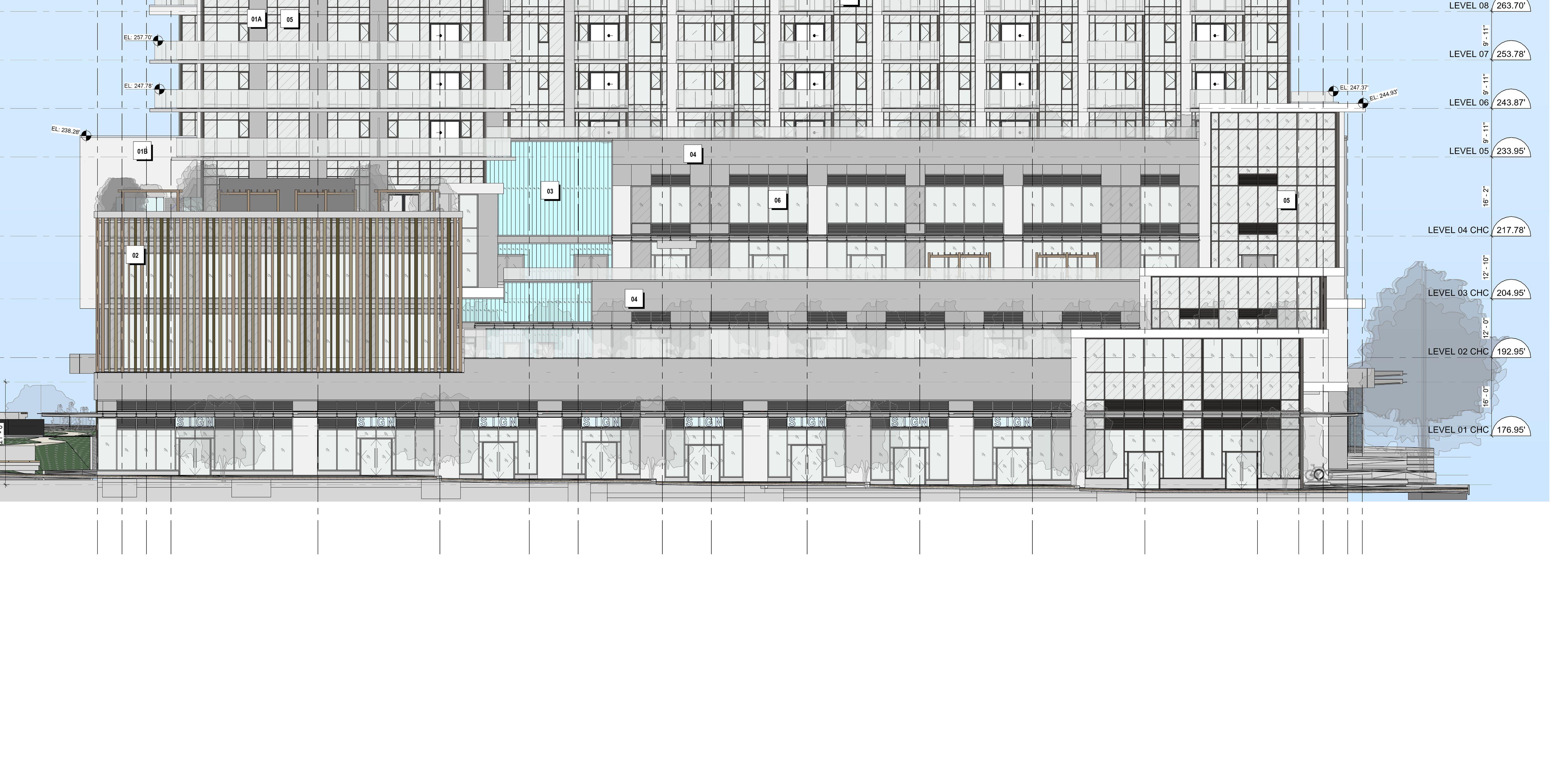
LEVEL 02
LEVEL 01
North Elevation
39
TECHNICAL DESIGN
INTERIOR
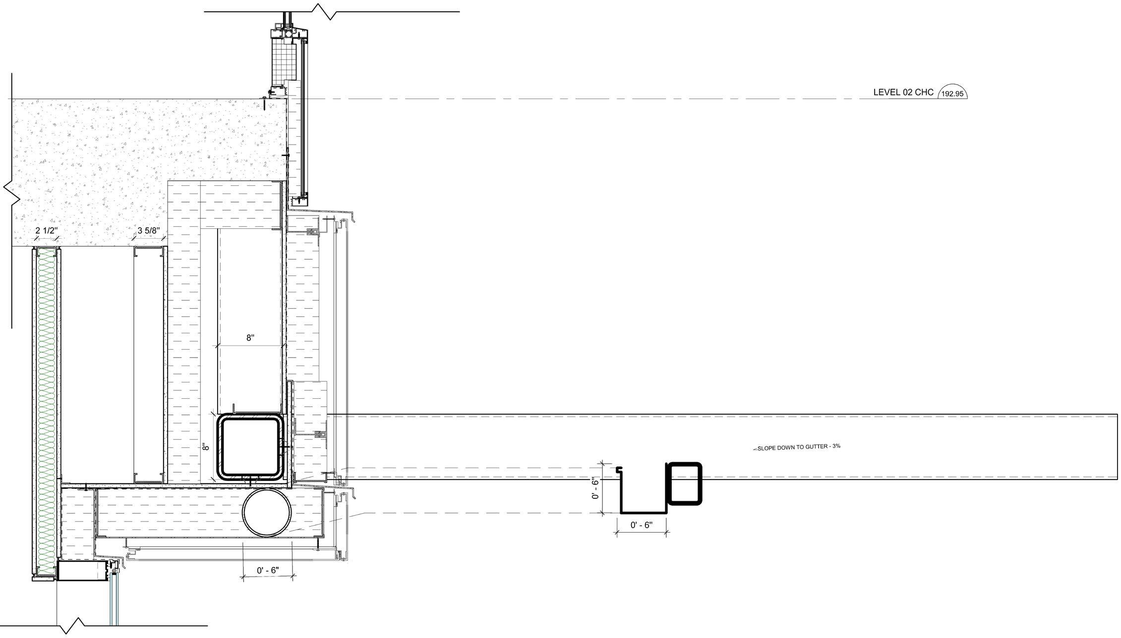
LEVEL 02
38 MM RIGID INSULATION
GLASS SPANDREL PANEL
150 MM RIGID INSULATION
150 MM STEEL STUD
PREFABRICATED METAL FLASHING
EXT. GRADE DRYWALL
EXTERIOR
WATER / VAPOUR BARRIER TO WRAP AROUND EXT. GRADE DRYWALL
ALUMINUM CLADDING WHITE FINISH
100 MM RIGID INSULATION
HSS - SEE STRUCTURAL DWGS
GUTTER BEYOND
SLOPE DOWN TO PIPE 2% MIN.
150 MM STEEL STUD
PIPE TO RAINWATER LEADER
TRANSLUCENT TEMPERED GLASS PANE
SLPOE DOWN TO GUTTER - 3%
HSS SECTION - STR. DWGS
MEMBRANE LINED 150 MM X 150 MM STEEL GUTTER
OPEN TO PLANTER BELOW
Building Canopy Detailing 2: Interface with Interior Conditioned Space B
B
40
LEVEL 02
LEVEL 01
North Elevation
41
South Elevation
Storefront Option 1: 12 CRU's all at different elevations allows for smooth continuation of accessible path of travel in front of all CRU’s; disadvantage is that it is harder for CRU’s to be combined in the future, which will require to introduce internal ramp (s) within combined CRU’s
South Elevation
Storefront Option 2: 10 CRU's, with every two CRU's at the same elevation allows for every two CRU's to be easily combined in the future without building internal ramps; requries the accessible path of travel in front of the CRU's to go round the steps
U UP DN DN CRU UNIT #07 CRU UNIT #08 CRU UNIT #09
UNIT #10 ± 7 " ± 9 " MATCHLINE - NW M A T C H L I N E S E MATCHLINE - SW M A T C H L I N E S W 10 U UP DN DN CRU UNIT #07 CRU UNIT #08
UNIT #09
#10 ± 7 " ± 9 " MATCHLINE - NW M A T C H L I N E S E MATCHLINE - SW M A T C H L I N E S W 10
CRU
CRU
CRU UNIT
CRU#12 CRU#11 CRU#10
CRU#10
CRU#9
CRU#9
CRU#8
CRU#8
CRU#7 CRU#6
42
DESIGN
TECHNICAL
There is a total of 4 feet grade change east-west wise along the south storefront of the building. Different options of how to design the elevation change of the CRU Units and the plaza in front of them are explored,
considering 1) the possibility of combining CRU’s in the future, 2) the accessibility of path of travel both outside of the stores, as well as inside the stores, including the scenarios where some of them are combined.
P
CRU UNIT #01
CRU UNIT #02
CRU UNIT #03
CRU UNIT #04
CRU UNIT #05
± 1 0 " ± 7 " MATCHLINE
CRU UNIT #06
- NW MATCHLINE - SW
10
CRU#7
CRU#6
CRU#6
CRU#5
CRU#5
CRU#4
CRU#4
CRU#3
CRU#3
CRU#2
CRU#2
CRU#1
CRU#1
43
44
TECHNICAL DESIGN
BASSANO
Role:
Explore design options during Design Development phase, e.g. planter and parapet wall conditions, and building canopy design;
Material research;
Building Code and by-laws research; Coordinate with engineering disciplines;
produce drawing set for Building Permit application, e.g. stair and core drawings, and window schedules;
Attend and write meeting minutes during consultant meetings
Location: Burnaby, BC
Design Development phase (2023), Construction Documentation phase (2023-present)
Project Type: New Construction
Gross Floor Area: 326,250 SF
No. of Stories: 43
Budget: CAD$48,500,000
Occupancy: Residential, Retail, Office
Software: Revit
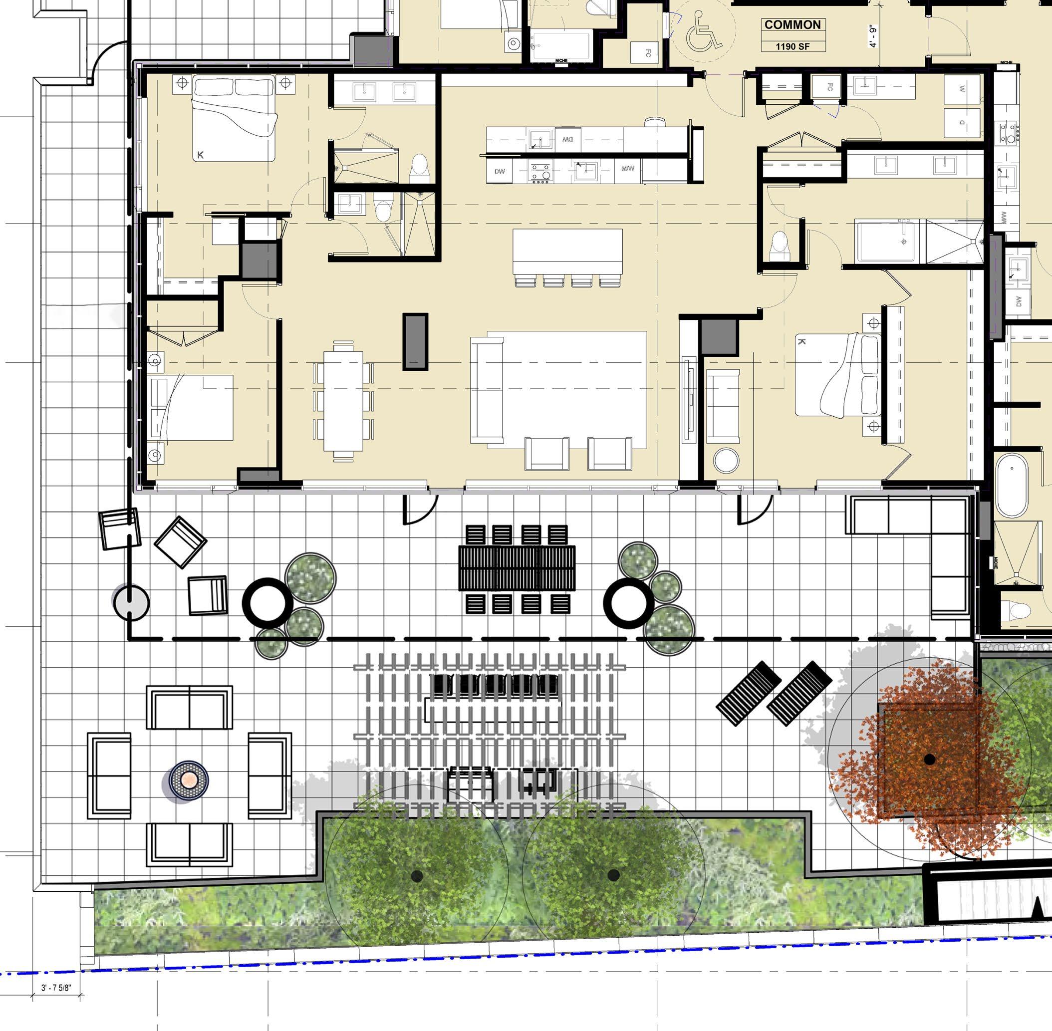
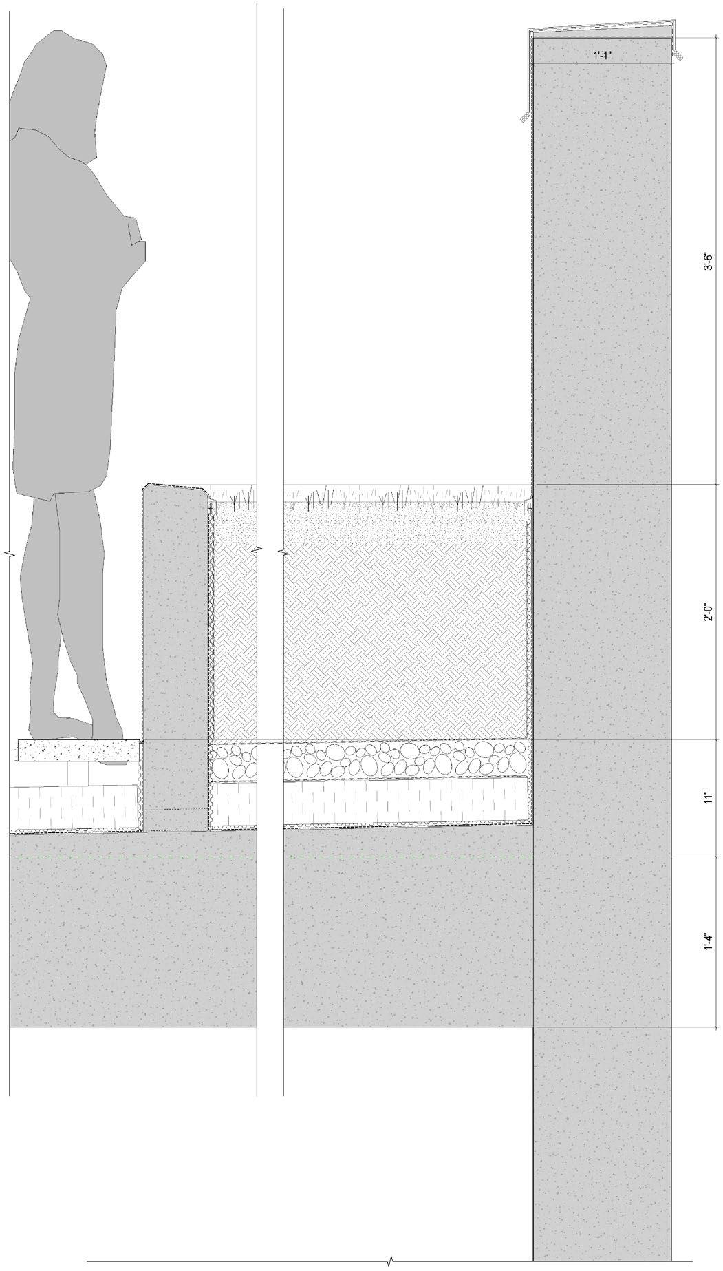
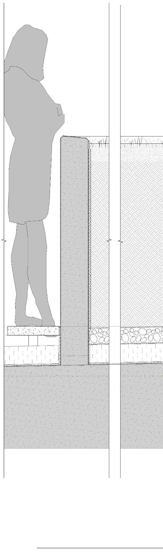
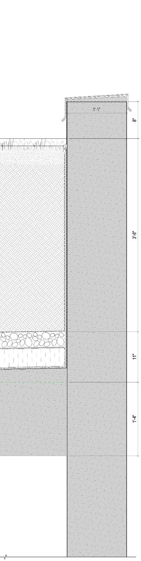
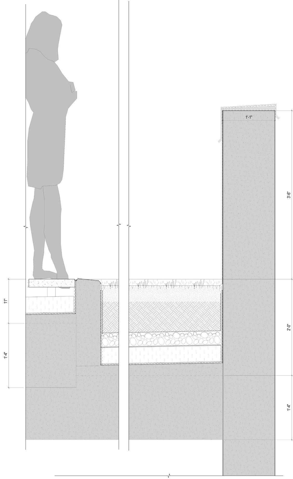
Bassano is a mix-used high rise. On the third level in the podium, there is this luxurious residential unit that has a vast terrace, and the task was to explore different options of the height of the planter v.s. the parapet wall, considering various factors, such as to continue the luxurious design style for the tenant, aesthetics, privacy, cost, and structural design.
45
TECHNICAL DESIGN
PAVERS
OVERFLOW SCUPPER IN WALL PAVERS
TERRACE
5% SLOPE DOWN 10% MIN.
EXTEND ROOFING MEMB. UP THE UPSTAND
MEMBRANE TERMINATION BAR
TOP OF PLANTER WALL
SEE LANDSCAPE BUILDUP
METAL FLASHING ON PEEL AND STICK MEMB. ON TREATED PLYWOOD
TERRACE
2% SLOPE
16" CONC. SLAB (SEE STR.) CONC. WALL (SEE STR.)
GUMLIP FLASHING TO PROTECT LEADING EDGE OF ROOF MEMBRANE AND DRAINAGE MAT TYP.
PAVERS
OVERFLOW SCUPPER IN WALL PAVERS
10% MIN.
EXTEND ROOFING MEMB. UP
MEMBRANE TERMINATION
TOP OF PLANTER
SEE LANDSCAPE BUILDUP
2%
16" CONC. (SEE
EXIT BELOW EXIT
Option 1
Higher parapet wall because of the required 3’ 6” nonclimbable height starting from the soil surface
lower
Tall (3’ 6”) planter; sight line may or branches of plants;
46
ROOFING THE UPSTAND
MEMBRANE TERMINATION BAR
PLANTER WALL
LANDSCAPE
SLOPE
CONC. SLAB STR.)
EXIT BELOW
TERRACE
5% SLOPE DOWN
CONC. WALL (SEE STR.)
METAL FLASHING ON PEEL AND STICK MEMB. ON TREATED PLYWOOD
GUMLIP FLASHING TO PROTECT LEADING EDGE OF ROOF MEMBRANE AND DRAINAGE MAT TYP.
10% MIN.
PAVERS
OVERFLOW SCUPPER IN WALL PAVERS
EXTEND ROOFING MEMB. UP THE UPSTAND
MEMBRANE TERMINATION BAR
TOP OF PLANTER WALL
SEE LANDSCAPE BUILDUP
5% SLOPE DOWN
Option 2
may only land on trunck
lower parapet allows visual connection
16" CONC. SLAB (SEE STR.)
2% SLOPE TO PLANTER DRAIN
16" CONC. SLAB (SEE STR.)
CONC. WALL (SEE STR.)
METAL FLASHING ON PEEL AND STICK MEMB. ON TREATED PLYWOOD
EXIT BELOW
Option 3
direct interaction with the planting area; special drainage and structural design requried for the inset planter; low parapet wall allows for visual connection
GUMLIP FLASHING TO PROTECT LEADING EDGE OF ROOF MEMBRANE AND DRAINAGE MAT TYP.
47
48
SKETCHES
49