
BRUGERMANUAL
BEDIENUNGSANLEITUNG
USER MANUAL
MANUEL
D’UTILISATEUR
BRUKERVEILEDNING

BRUKSANVISNING
KÄYTTÖOHJE
GEBRUIKERSHANDLEIDING
Mærkeplade/CE Zeichen/Manufacturer’s plate/Plaque signalétique/Merkeplate/ Märkplät
EN 13229:2001+A1:2003+A2:2004, EC.NO: 224
Notified Body: 1235
Produced at:
RAIS A/S, Industrivej 20, 9900 Frederikshavn, Danmark
19 Visio 2 L Left / Visio 2 L Right
Anordningen må kun installeres i forbindelse med ubrændbart materiale.
AFSTAND TIL BRÆNDBART, BAGVÆG
ABSTAND ZU BRENNBAREN BAUTEILEN, HINTEN
DISTANCE TO COMBUSTIBLE BACK WALL
DIST. ENTRE COMPOSANTS COMBUSTIBLES, ARRIÈRE
AFSTAND TIL BRÆNDBART, SIDEVÆG
ABSTAND ZU BRENNBAREN BAUTEILEN, SEITE
DISTANCE TO COMBUSTIBLE SIDE WALL
DISTANCE ENTRE COMPOSANTS COMBUSTIBLES, COTÉ
AFSTAND TIL BRÆNDBART, MØBLERING
ABSTAND VORNE ZU BRENNBAREN MÖBELN
DISTANCE TO FURNITURE AT THE FRONT
DISTANCE ENTRE COMPOSANTS COMBUSTIBLES, DEVANT
CO EMISSION (REL. 13% O2)

CO EMISSION IN DEN VERBRENNUNGSPRODUKTEN (BEI 13%O2)
EMISSION OF CO IN COMBUSTION PRODUCTS (AT 13%O2)
EMISSION CO DANS LES PRODUITS COMBUSTIBLES (À 13%O2)
STØV / STAUB / DUST / POUSSIÈRES:
RØGGASTEMPERATUR / ABGASTEMPERATUR /
FLUE GAS TEMPERATURE / TEMPÉRATURE DES GAZ DE FUMÉE:
NOMINEL EFFEKT / HEIZLEISTUNG /
THERMAL OUTPUT / PUISSANCE CALORIFIQUE:
VIRKNINGSGRAD / ENERGIEEFFIZIENZ / ENERGY EFFIENCY /EFFICACITÉ ÉNERGÉTIQUE:
DK: Brug kun anbefalede brændsler. Følg instrukserne i bruger manualen.
Anordningen er egnet til røggassamleledning og intervalfyring.
DE: Lesen und befolgen Sie die Bedienungsanleitung.
Zeitbrandfeuerstätte. Nur empfohlene Brennstoffe einsetzen.
UK: Fuel types (only recommended). Follow the installation and operating instruction manual. Intermittent operation.
F: Veuillez lire et observer les instructions du mode d’emploi. Foyer à durèe de combustion limitèe, homologué pour cheminée à connexions multiples. Utiliser seulement les combustibles recommandés.
Not to be used in a shared flue
15a B-VG
DK: mm SE BRUGERVEJLEDNING
DE: mm SIEHE BEDIENUNGSANLEITUNG
UK: mm SEE USER MANUAL
FR: mm CONSULTEZ LE GUIDE DE L’UTILISATEUR
DK: mm SE BRUGERVEJLEDNING
DE: mm SIEHE BEDIENUNGSANLEITUNG
UK: mm SEE USER MANUAL
FR: mm CONSULTEZ LE GUIDE DE L’UTILISATEUR
DK: 1250mm SE BRUGERVEJLEDNING
DE: 1250mm SIEHE BEDIENUNGSANLEITUNG
UK: 1250mm SEE USER MANUAL
FR: 1250mm CONSULTEZ LE GUIDE DE L’UTILISATEUR
0,098 % / 1226 mg/Nm³ 28 mg/Nm³
DK: BRÆNDE
DE: HOLZ
UK: WOOD
FR: BOIS
Produced for:
Raumheizer für feste Brennstoffe
Appliance fired by wood Poêle pour combustibles solides
ATTIKA FEUER AG, Brunnmatt 16, CH-6330 Cham / RAIS A/S, Industrivej 20, DK-9900 Frederikshavn
RAIS/attika VISIO 3 L
Mærkeplade/CE Zeichen/Manufacturer’s plate/Plaque signalétique/Merkeplate/ Märkplät
19
EN 13229:2001+A1:2003+A2:2004, EC.NO: 224
Notified Body: 1235
Produced at:
RAIS A/S, Industrivej 20, 9900 Frederikshavn, Danmark
Visio 3 L
Anordningen må kun installeres i forbindelse med ubrændbart materiale.
AFSTAND TIL BRÆNDBART, BAGVÆG
ABSTAND ZU BRENNBAREN BAUTEILEN, HINTEN
DISTANCE TO COMBUSTIBLE BACK WALL
DIST. ENTRE COMPOSANTS COMBUSTIBLES, ARRIÈRE
AFSTAND TIL BRÆNDBART, SIDEVÆG
ABSTAND ZU BRENNBAREN BAUTEILEN, SEITE
DISTANCE TO COMBUSTIBLE SIDE WALL
DISTANCE ENTRE COMPOSANTS COMBUSTIBLES, COTÉ
AFSTAND TIL BRÆNDBART, MØBLERING
ABSTAND VORNE ZU BRENNBAREN MÖBELN
DISTANCE TO FURNITURE AT THE FRONT
DISTANCE ENTRE COMPOSANTS COMBUSTIBLES, DEVANT
CO EMISSION (REL. 13% O2)
CO EMISSION IN DEN VERBRENNUNGSPRODUKTEN (BEI 13%O2)
EMISSION OF CO IN COMBUSTION PRODUCTS (AT 13%O2)
EMISSION CO DANS LES PRODUITS COMBUSTIBLES (À 13%O2)
STØV / STAUB / DUST / POUSSIÈRES:
RØGGASTEMPERATUR / ABGASTEMPERATUR / FLUE GAS TEMPERATURE / TEMPÉRATURE DES GAZ DE FUMÉE:
NOMINEL EFFEKT / HEIZLEISTUNG / THERMAL OUTPUT / PUISSANCE CALORIFIQUE:
VIRKNINGSGRAD / ENERGIEEFFIZIENZ / ENERGY EFFIENCY /EFFICACITÉ ÉNERGÉTIQUE:
DK: Brug kun anbefalede brændsler. Følg instrukserne i bruger manualen. Anordningen er egnet til røggassamleledning og intervalfyring.
DE: Lesen und befolgen Sie die Bedienungsanleitung. Zeitbrandfeuerstätte. Nur empfohlene Brennstoffe einsetzen.
UK: Fuel types (only recommended). Follow the installation and operating instruction manual. Intermittent operation.
F: Veuillez lire et observer les instructions du mode d’emploi. Foyer à durèe de combustion limitèe, homologué pour cheminée à connexions multiples. Utiliser seulement les combustibles recommandés.
Not to be used in a shared flue
15a B-VG
DK: mm SE BRUGERVEJLEDNING
DE: mm SIEHE BEDIENUNGSANLEITUNG
UK: mm SEE USER MANUAL
FR: mm CONSULTEZ LE GUIDE DE L’UTILISATEUR
DK: mm SE BRUGERVEJLEDNING
DE: mm SIEHE BEDIENUNGSANLEITUNG
UK: mm SEE USER MANUAL
FR: mm CONSULTEZ LE GUIDE DE L’UTILISATEUR
DK: 1100mm SE BRUGERVEJLEDNING
DE: 1100mm SIEHE BEDIENUNGSANLEITUNG
UK: 1100mm SEE USER MANUAL
FR: 1100mm CONSULTEZ LE GUIDE DE L’UTILISATEUR
0,098 % / 1226 mg/Nm³
28 mg/Nm³
225 °C
10,3 kW 81 %
DK: BRÆNDE
DE: HOLZ
UK: WOOD
FR: BOIS
Produced for:
Raumheizer für feste Brennstoffe
Appliance fired by wood
Poêle pour combustibles solides
ATTIKA FEUER AG, Brunnmatt 16, CH-6330 Cham / RAIS A/S, Industrivej 20, DK-9900 Frederikshavn
Label for: RAIS Visio 3 L
Indstilling af spjæld / Einstellung der Luftklappe / Adjustment of the air damper / Réglage du volet d’air / Innstilling av spjeldet / Inställning av spjället


Position 1 - Posisjion 1


Position 2 - Posisjion 2
Position 3 - Posisjion 3

Optænding og påfyldning / Anzünden und Nachlegen / Lighting and fuelling / Allumage et remplissage / Opptenning og påfylling / Upptänding och påfyllning
VISIO 3 positioner af spjældhåndtag
VISIO 3 positioner af spjældhån
VISIO 3 positioner af spjældhåndta
FIRE ENVIRONMENTALLY FRIENDLY!
5 Eco-friendly advices for sensible heating - common sense both environmentally and economically.
1. Effective lighting. Use small pieces of wood (fir tree) and a suitable fire lighter, for example paraffined wood wool/sawdust. Open the air damper, so plenty of air is fed to the stove and the gases from the heated wood can burn rapidly.
2. Light the fire with only little wood at a time - this gives the best combustion. Remember plenty of air for every time new wood is added.
3. When the flames are diminished, adjust the air damper so that the air supply is reduced.
4. When only glowing embers remain, air flow can be reduced further, so heating demand is just covered. With a lower air supply the charcoal will burn slower and the heat loss through the chimney is reduced.
5. Use only dry wood - ie. wood with a humidity of 15 to 20%.
RECYCLING:
The oven is wrapped in packaging that is recyclable. This must be disposed of according to national rules regarding the disposal of waste.
The glass can not be reused. The glass should be discarded along with the residual waste from ceramics and porcelain. Pyrex glass has a higher melting temperature and therefore can not be reused.
If discarded you make an important positive contribution to the environment.
Introduction
Thank you for purchasing a RAIS/attika wood burning stove.
A RAIS/attika wood burning stove is more than just a heat source. It also shows that you care about design and quality in your home.
To make the most of your wood burning stove it is important that you read the manual thoroughly, before installing and using it.
In the case of warranty coverage, and for general queries regarding your wood burning stove, it is important that you know the stove’s production number. We therefore recommend that you write down the number in the table below.

The production number is located in the bottom left corner of the wood-burning stove.
Date: Distributor:
RAIS/attika – wood-burning stoves are tested repeatedly in terms of safety, as well as material and manufacturing quality. We grant warranty on all models, starting with the date of installation.
The warranty refers to:
• documented malfunctions due to faulty manufacture
• documented material defects
The warranty does not cover:
• door and glass seals
• ceramic glass
• chamber lining
• appearance of the surface structure or natural stone texture
• appearance or changes of colour of the stainless steel or patina surfaces
• expansion noise
The warranty is invalidated in case of:
• damages, caused by overfiring
• damages, caused by external influence and the use of unsuitable fuels
• non-observance of statutory or recommended installation guidelines, and modificatons to the wood-burning stove
• non-observance of service and care provisions
Please contact your retailer in the event of damage. We determine the way to repair the damage, in case of warranty claims. In the event of repair, we ensure proper and professional execution.
Warranty claims submitted for additionally delivered or repaired parts are subject to national/EU laws and regulations in terms of renewed warranty periods.
Please contact RAIS A/S for the applicable warranty provisions.
VISIO L are inset stoves with a vertically operated door.
Specifications
DTIref.:300-ELAB-2383-EN VISIO L 2 VISIO L 3
Nominal output (kW): 10.3
Min./Max. output (kW): 8 - 12
Heating area (m2): 200
Stove’s width/depth/height (mm): 1141 x 610 X 1765
Combustion chamber’s width/ depth/height (mm): 708 X 256 X 541
Recommended amount of wood when fuelling (kg).
Distributed on 2-4 logs of wood of approx. 30 cm
Min. uptake / Min. draught (Pascal): -11 Weight (kg): approx 293
X 634 X 1765
Intermittent operation: Refuelling should be undertaken within 58 minutes.
DTI
Danish Technological Institute
Teknologiparken Kongsvang Allé 29, DK-8000 Aarhus C
Danmark
www.dti.dk
Telefon: +45 72 20 20 00
Fax: +45 72 20 10 19
Dimensional drawings
NB: The flue spigot at the top outlet can be turned freely. (Radius 102 mm).
VISIO L 2
With top outlet
Convection
RAIS/attika stoves are convection stoves. Convection means that there is a circulation of air, which ensures that the heat is distributed more evenly throughout the entire room. The cold air is sucked in at the base of the stove up through the convection channel, which runs along the stove’s combustion chamber. The heated air pours out at the top of the stove, which ensures a circulation of warm air throughout the room.
Note, however, that all exterior surfaces become hot during use - so take extreme care.
Use the insert optimally.
By installing hot air nozzles and flexible hoses (or similar) on top of the stove, it is possible to ”move” the heat to other rooms.
Consider the placement of convection and outlet holes. Ensure that the area requirements are respected and that the holes are not blocked from the outside. There may be discoloration of the wall above the stove doors, and above the convection outlet holes. This is due to the ascending hot air.
RAIS/attika accepts no liability for installation or consequential damages.
Chimney
The chimney is the driving force which makes the stove function. In order for the stove to perform satisfactorily the chimney height must be sufficient to ensure the correct draught of 14 to 18 Pa so as to clear the products of combustion and prevent problems of smoke emanating into the room when firing.
NOTE: A chimney height of not less than 4.5 metres measured vertically from the outlet of the stove to the top of the chimney should be satisfactory. Alternatively the calculation procedure given in BS 5854:1980 may be used as the basis for deciding whether a particular chimney design will provide sufficient draught.
The outlet from the chimney should be above the roof of the building in accordance with the provisions of Building Regulations Approved Document J.
If installation is into an existing chimney then it must be sound and have no cracks or other faults which might allow fumes into the house. Older properties, especially, may have chimney faults or the cross section may be too large i.e. more than 230 mm x 230 mm. Remedial action should be taken, if required, seeking expert advice, if necessary. If it is found necessary to line the chimney then a flue liner suitable for solid fuel must be used in accordance with Building Regulations Approved Document J.
Any existing chimney must be clear of obstruction and have been swept clean immediately before installation of the stove. If the stove is fitted in place of an open fire then the chimney should be swept one month after installation to clear any soot falls which may have occurred due to the difference in combustion between the stove and the open fire.
If there is no existing chimney then either a prefabricated block chimney in accordance with Building Regulations Approved Document J or a twin walled insulated stainless steel flue to BS 1856-1 can be used. These chimneys must be fitted in accordance with the manufacturer’s instructions and Building Regulations.
A single wall metal fluepipe is suitable for connecting the stove to the chimney but is not suitable for using for the complete chimney. The chimney and connecting fluepipe must have a minimum diameter of 180 mm. Any bend in the chimney or connecting fluepipe should not exceed 45°. 90°bends should not be used.
Combustible material should not be located where the heat dissipating through the walls of fireplaces or flues could ignite it. Therefore when installing the stove in the presence of combustible materials due account must be taken of the guidance on the separation of combustible material given in Building Regulations Approved Document J and also in these stove instructions.
If it is found that there is excessive draught in the chimney then either an adjustable flue damper or alternatively a draught stabiliser should be fitted. The adjustable flue damper should not close off the flue entirely but should in its closed position leave a minimum continuous opening free area of at least 20 % of the total cross sectional area of the flue or fluepipe.
Material selection
Choose non-combustible materials for panels/bricks with a thermal resistance greater than 0.03 m2xK/W. Thermal resistance is defined as the thickness (in m) divided by the wall’s lambda value. Consult with your installer/chimney sweep. During testing, the wood-burning stove is installed in a cabinet made from nonflammable 50 mm calcium silicate panels (Skamotec 225).
Installation
Adequate provision e.g. easily accessible soot door or doors must be provided for sweeping the chimney and connecting fluepipe.
You should also familiarise yourself with the draught conditions for chimneys with 2 flues.

The stove is supplied with a ø200 mm flue outlet spigot. The stove is approved with a ø180 mm flue outlet spigot, which can be retrofitted.
The flue spigot can be changed from top outlet to back outlet. The clamp on the outlet is loosened and adjusted as desired.
NOTE!
if the stove is installed with a back outlet, the back wall must be non combustible ( e.g.a brick wall).
For strong draughts, the chimney or flue should be fitted with a draught stabiliser. In which case, it is important to ensure that there is a free flow-through area of minimum 20 cm² when the regulating gate is shut. Otherwise, the fuel energy may not be used optimally. If, at any time, you are unsure about the condition of the chimney, you should contact a chimney sweep.
Remember that access to the access door should be kept clear. Make sure to establish access to cleaning the stove, flue collar and pipe.
Mounting the reflektor plate - VISIO L 2
The stove is fitted with a reflector plate on the back side. The reflector must be moved to the right position, under installation of the stove.


Remove the two screws, move the reflector and fix it again in the right position. (as shown)
Mounting the reflector plate - VISIO L 3
The stove is fitted with a reflector plate.
Dismount the reflector plate and turn it upside down. Mount the plate by reusing the screws at the bottom.
Bend the cut-outs and mount the plate to the top of the stove.
Transport safety
Before installing the stove remove the transport safety:

• on VISIO 1 remove 2 screws on the side.
• on VISIO 2 remove 1 screw on the side.
• on VISIO 3 remove 2 screws on the back side.

VISIO 2 L
Applies to installation in non-flammable panels or in brick. If other materials are used, they must have better or the same characteristics as 50 mm Skamotec 225.
To achieve the necessary distances from the wood-burning stove to the panel/brickwork, the internal dimensions of the cassette must be 665 x 1195 x 1950 mm. If this is complied with, the exterior rear side of the cassette may lie against a flammable wall. There must be a top plate in the cabinet just above the convection ejection.
A fireplace insert may never be installed in a cavity that is too tight, since steel expands when heated.
Hole dimensions (height x width x depth) min. 570.5 x 999.3 x 549.5 mm (interior dimensions). Hole dimension forwood-burning stove with installation frame.Aheight of568 mm provides an airgap of5 mm above the top frame.This airgap is necessary because the wood-burning stove will expand when heating up.Ifthis airgap is not created, it can result in damage to the brickwork!
Minimum distance to flammable material: Visio L 2
Convection air area above stove with panel installation. Must be at least 750 cm², the area can be divided into several cavities.
The minimum distance from the top of the installation cassette/convection opening to the combustible ceiling is 500 mm
The minimum distance from the insulated chimney to the flammable rear wall is 110 mm
Convection air area above stove with panel installation. Must be at least 375 cm², the area can be divided into several cavities.
If the sidewall is flammable, the wood-burning stove must be moved at least 100 mm away the wall!
There must be at least 100 mm between the wood-burning stove and rear panel in the cassette.
Side clearance for flammable from front window min. 250mm!
Minimum distance for furniture at side window is 800 mm
Minimum distance from front window to furniture is 1250 mm
If the side window is to be flush with the wall, the first 650 mm must be made of a non-flammable panel. (FX. Skamotec 225 - 50 mm or equivalent)
If the front window is to be flush with the wall, the first 700 mm must be made of a non-flammable panel. (FX. Skamotec 225 - 50 mm or equivalent)
Applies to installation in non-flammable panels or in brick. If other materials are used, they must have better or the same characteristics as 50 mm Skamotec 225.
To achieve the necessary distances from the wood-burning stove to the panel/brickwork, the internal dimensions of the cassette must be 700 x 988 x 1950 mm. If this is complied with, the exterior rear side of the cassette may lie against a flammable wall. There must be a top plate in the cabinet just above the convection ejection.
A fireplace insert may never be installed in a cavity that is too tight, since steel expands when heated.
Hole dimensions (height x width x depth) min. 568 x 1088 x 504 mm (interior dimensions). Holedimension forwood-burning stove with installation frame.Aheight of 568 mm provides an airgap of5 mm above the top frame.This airgap is necessary because the wood-burning stove will expand when heating up. Ifthis airgap is not created, it can result in damage to the brickwork!
The minimum distance from the insulated chimney to the flammable rear wall is 110 mm
The minimum distance from the top of the installation cassette/convection opening to the combustible ceiling is 300 mm
If the sidewall is flammable, the wood-burning stove must be moved at least 100 mm from the wall!
If the side window is to be flush with the wall, the first 250 mm must be made of a non-flammable panel. There must be at least 100 mm between the wood-burning stove and rear panel in the cassette.
Minimum distance for furniture at side window is 700 mm
65 K point
Minimum distance from front window to furniture is 1100 mm
CONVECTION AIR
There is a minimum area requirement for convection air. This must be complied with because to avoid the risk of overheating and because of the distance to flammable material. Ensure that the wood-burning stove can draw in convection air underneath itself. And can transport the air out again, over itself.
With installation in a completely non-flammable structure there are no minimum convection air area requirements but it is recommended that area is added from the panel installation since the brickwork can crack at excessively high temperatures.
Convection air area above stove with panel installation. Must be at least 1000 cm², the area can be divided into several cavities.
Convection air area below stove with panel installation. Must be at least 500 cm², the area can be divided into several cavities.
In order to get the most out of your stove, guide the warm air out of the convection grate. Position the convection grate just below the non-flammable top plate. The convection cavity can also be placed on top of the cassette.
NB!
The insulated part of the chimney must extend all the way down to the flue spigot.
Air-system
When mounting the Air system ensure that the air control system provides fresh air from the outside.
In order for the Air system to function, you have to ensure in the structure that no vacuum occurs in the housing.
If convection grates are installed, be sure not to block them. Air system (accessory) is connected to the bottom of the stove.
For the Installer
Finally before firing the stove for the first time a check should be made to ensure that the assembly and stove installation has been satisfactory and that there are no leaks in any seals in the appliance and appliance connections to the chimney.
Ensure that the appliance and chimney flue are functioning correctly before finally handing over to the user. If necessary read the later parts of this manual for guidance on care required when first lighting.
Inform the user that the appliance has been commissioned and ready to use and give instruction on the safe operation of the stove.
These Instructions must be left with the user and the user should be instructed to keep them in a safe place.
Operating instructions
Please note that HETAS Ltd Appliance Approval only covers the use of dry seasoned wood logs on this appliance. HETAS Ltd Approval does not cover the use of other fuels either alone or mixed with the wood logs, nor does it cover instructions for the use of other fuels.
Fuel
The stove has been tested in accordance with EN 13229:2001, EN 13229:2001/ A1:2003, EN 13229:2001/A2:2004, and NS 3058 for stoking split, dried birchwood, and is
approved for broad-leaved/coniferous tree wood. The firewood must have a water content of 15-20% and its max. length should be 30 cm.
Stoking with wet firewood causes both soot, environmental pollution and bad fuel economy. Freshly cut wood contains approx. 60-70% water and is thoroughly unsuitable for stoking. Count min. 1-2 years of storage time for newly cut wood before using.
Wood with a diameter of more than 100 mm should be split. Regardless of wood size, it should always have at least one surface area free of bark.
We do not recommend stoking with painted, laminated or impregnated wood, wood with a synthetic surface, painted refuse wood, chipboard, plywood, domestic waste, paper briquettes and pit coal, as this will produce malodorous smoke, which could be poisonous.
When firing with the above-mentioned items and amounts larger than those recommended, the stove is subjected to a larger amount of heat, which results in a higher chimney temperature and lower efficiency. This can result in the stove and chimney becoming damaged and would void the warranty.
The calorific value of the firewood is closely connected to the moisture level of the firewood. Moist firewood has a low heat value. The more water the wood contains, the more energy it takes for this water to vaporise, resulting in this energy being lost.
ONLY USE RECOMMENDED FUELS
The following table shows the calorific value of different types of wood, which have been stored for 2 years, and which have a residual moisture of 15-17%.
Kg dry wood pr. m3 compared to beech/oak
1 kg of wood yields the same heat energy irrespective of wood type.
1 kg beech merely takes up less space than 1 kg of fir.
Drying and storage
Drying wood takes time. Proper air drying takes approx. 2 years.
Here are some tips:
• Store the wood sawn, split and stacked in an airy, sunny place, which is protected against rain (the south side of the house is particularly suitable).
• Store the firewood stacks at a hand’s breadth apart, as this ensures that the air flowing through takes the moisture with it.
• Avoid covering the firewood stacks with plastic, as this prevents the moisture from escaping.
• It is a good idea to bring the firewood into the house 2-3 days before you need it.
Regulating the combustion air
The stoves are equipped with a one-handed operating lever for regulating the damper. The stove-specific regulating mechanisms can be seen on the diagrams (next section).
The primary air is added to the primary combustion zone at the bottom of the burning chamber, i.e. the bed of glowing embers. This cold air is only used in the lighting stage.
Secondary air is the air, added to the gas combustion zone, meaning air, which contributes to the combustion of the pyrolysis gasses (preheated air, used for cleaning the glass and combustion). This air is sucked through the damper and is pre-heated through the side and back channels and then emitted as hot scavenging air onto the glass. The hot air rinses the glass and keeps it soot-free.
Tertiary air at the back of the burning chamber at the top (row of holes) ensures the combustion of the final gas residues and particles before leaving through the chimney.
By setting the interval between position 1 and 2, the energy content in the firewood is used optimally, as there is oxygen for combustion and for the burning of the pyrolysis gasses. When the flames are a clear yellow the damper has been set correctly. Finding the correct position comes with time after regular use of the stove.
It is not recommended that you turn it down completely. A mistake commonly made is shutting the damper too early because it feels too hot. This results in dark smoke emanating from the chimney and the calorific value of the firewood is not being used to its fullest.
Room ventilation
There must not be an extractor fan fitted in the same room as the stove as this can cause the stove to emit smoke and fumes into the room.
The stove requires a permanent and adequate air supply in order for it to operate safely and efficiently.
In accordance with Building Regulations Approved Document J a permanent air supply vent is required into the room in which the stove is installed to provide combustion air.
This air vent should not under any circumstances be shut off or sealed.
Using the wood burning stove
Adjustment of the air damper - the damper has 3 settings For reference see drawing (in the front of the manual).
Position 1
Pull the lever to the left. The damper is almost closed; there is a minimal air intake. This position must be avoided during normal operation. Notice warning in the next section.
Position 2
Pull the lever until first click (middle position). This position gives only secondary air. During normal stoking the lever is set between position 1 and 2. When the flames are clear and yellow, the damper is set correctly, i.e. resulting in a slow/optimal burning.
Position 3
Pull the lever to the right. The air damper is completely open and gives full ignition air (primary) and secondary air.
The position is for the lighting stage and refuelling and is not used under normal operation.
First usage
A careful start pays off. Start with a small fire, so that the wood burning stove can get accustomed to the high temperature. This gives the best start and any damage is avoided.
Be aware that a strange but harmless odour and smoke concoction may emanate from the surface of the stove, the first time you fire up. This is because the paint and materials need to harden. The odour disappears quickly, but you should check the ventilation and draught, if possible. See also, the IMPORTANT warning notice below about persistent fumes.
During this process you must be careful not to touch the visible surfaces/glass (very hot!), and it is recommended that you regularly open and close the door to prevent the door seal from sticking.
The stove may also produce “clicking noises” during heating and cooling, caused by the large temperature differences which the material is subjected to.
Never use any type of liquid fuel for kindling or maintaining the fire. There is a danger of explosion.
The stove gets very hot when in use always wear protective gloves when tending the stove.
If the stove has not been used for a while, follow the steps as if you were using it for the first time.
IMPORTANT - Warning Note!
Properly installed, operated and maintained this appliance will not emit fumes into the dwelling. Occasional fumes from de-ashing and re-fuelling may occur. However, persistent fume emission is potentially dangerous and must not be tolerated. If fume emission does persist, the following immediate actions should be taken:
1. Open doors and windows to ventilate room.
2. Let the fire out or eject and safely dispose of fuel from the appliance.
3. Check for flue or chimney blockage, and clean if required.
4. Do not attempt to relight the fire until the cause of the fume emission has been identified and corrected. If necessary seek expert advice.
IMPORTANT - Warning Note!
Do not use an aerosol spray on or near the stove when it is alight.
IMPORTANT - Safety advice!
When using the stove in situations where children, aged and/or infirm persons are present a fireguard must be used to prevent accidental contact with the stove. The fireguard should be manufactured in accordance with BS 8423:2002 (Replaces BS 6539).
If airsystem is connected, the valve must be open.
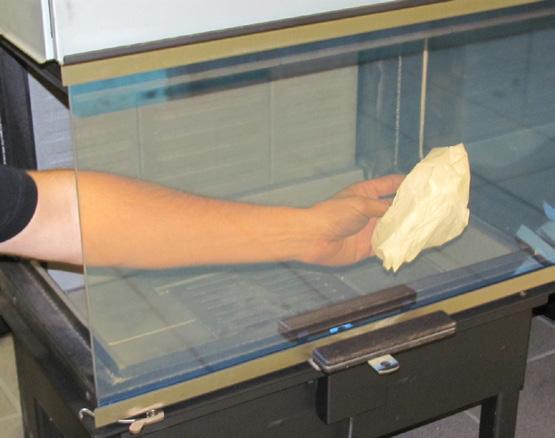
Open a door or window close to the wood burning. If there is a “storm” in the stove coming from the chimney, it is advisable to place a screwed-up piece of newspaper between the upper baffle plate and the chimney, set the paper on fire, and wait until you hear a “rumbling” noise in the chimney. This means that there definitely is a draught in the chimney and you avoid smoke in the room.
”Top-Down” lighting
For reference see photos (back of manual).
• Open the door fully until it is locked in the open position.
• Start by placing approx. 1kg of wood - 2 pcs. of wood - (photo 1) in the bottom of the combustion chamber. Place approx. 1.2 kilograms of dry firewood (photo 2), split into kindling sticks, and a couple of alcohol briquettes or similar.
• Light the fire (photo 3+4).
• Set the air damper to fully open pos. 3 (approx 15 min.), then at pos. 2.
• Close the door, leaving the door ajar approx 1-2 cm.
Advarsel
Warning!!

Hvis brændet kun ulmer eller ryger, og der tilføres for lidt luft, udvikles der uforbrændte røggasser.
If the firewood is only burning slowly without flames or is smoking, and too little air is added, unburned exhaust gasses are developed. Exhaust gasses can be ignited and explode, leading to damage to material and possibly personal injury.

Røggas kan antændes og eksplodere. Det kan give skader på materiel og i værste fald på personer.
Hvis brændet kun ulmer eller ryger, og der tilføres for lidt luft, udvikles der uforbrændte røggasser. Røggas kan antændes og eksplodere. Det kan give skader på materiel og i værste fald på personer.
Never close the air supply completely when lighting a fire in the stove. Sample photos

Luk aldrig helt for lufttilførslen, når der tændes op i ovnen.
Hvis der kun er få gløder tilbage, skal der tændes op forfra. Hvis man bare lægger brænde på tændes bålet ikke, derimod udvikles der uforbrændte
røggasser.
If there are only a few embers remaining you must light the fire again.
Luk aldrig helt for lufttilførslen, når der tændes op i ovnen. Hvis der kun er få gløder tilbage, skal der tændes op forfra. Hvis man bare lægger brænde på tændes bålet ikke, derimod udvikles der uforbrændte røggasser.
If you just add firewood the fire will not be lit, but unburned exhaust gasses will develop.
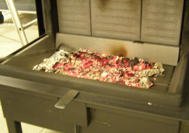
Her er der lagt træ på et for lille glødelag, og der tilføres for lidt luft - røgudvikling begynder.
Her er der lagt træ på et for lille glødelag, og der tilføres for lidt luft - røgudvikling begynder.
Here firewood has been added to an ember layer which is too small, and the air flow is too small - smoke is developed.

Undgå meget kraftig røgudviklingfare for røggaseksplosion.
Undgå meget kraftig røgudviklingfare for røggaseksplosion.
Avoid heavy smoke - danger of exhaust gas explosion.


Ved meget kraftig røgudvikling, åbn luftspjældet helt, samt eventuel låge på klem eller tænd op forfra.
Ved meget kraftig røgudvikling, åbn luftspjældet helt, samt eventuel låge på klem eller tænd op forfra.
In case of very heavy smoke, open the damper and the door and light the fire again.
Cleaning and care Glass
Most woodstoves use a ceramic glass product which is resistant to heat but requires cleaning to keep its appearance. Soot or opaque marks can easily cleaned if the marks are fresh, however If you leave the glass dirty for any length of time the acid from the wood can etch the surface of the glass permantley (wet unseasoned wood, soft wood such as used in the building industry, pallet wood should be avoided). Only clean when cold.
Use only stove glass cleaners to remove heavy tar/ soot deposits. All other marks can normally be removed with a damp cloth, then dry with a clean cloth or newspaper, do not let the glass dry before applying a dry clean cloth. With more stubborn marks i.e. opaque areas/frosting, you need put a small amount of wood ash on a clean damp cloth. If the opaque mark/frosting doesn’t come out, contact your dealer for a special remover.
Paint finish
The appliance has been coated with a high temperature paint which can last for years.
Do not clean with a damp cloth or any cleaning products as they can cause rust or discolouration. Only clean when cold use a brush with soft bristles or dust with a lint free cloth. Only re-spray when necessary.
The wood burning stove and the chimney must be serviced by a chimney sweep twice a year. During cleaning and care, the stove must be cold.
Prolonged period of non-use:
If the stove is to be left unused for a prolonged period of time then it should be given a thorough clean to remove ash and unburned fuel residues. To enable a good flow of air through the appliance to reduce condensation and subsequent damage, leave the air controls fully open.
Prior to a new heating season, it should be checked that the chimney and smoke gas connector are not blocked.
Maintenance/spare parts
Especially movable parts wear down during frequent use. Door seals are also wear parts. Only use original spare parts. We recommend service performed by your dealer after completion of a heating period.
Combustion chamber lining
The combustion chamber lining protects the body of the wood-burning stove against the heat from the fire. The large temperature fluctuations may result in cracks in the plates of the combustion chamber lining, which however have no effect on the functional capacity of the wood-burning stove. They do not have to be replaced unless they are crumbling away due to many years of use. The plates of the combustion chamber lining are only inserted and are easy to replace by your dealer or yourself.
Movable parts
Door hinges and door locks must be lubricated as required. We recommend that only our own lubricating spray is used, as the use of other products may lead to the formation of odours and residues. Contact your dealer to obtain the lubricating spray.
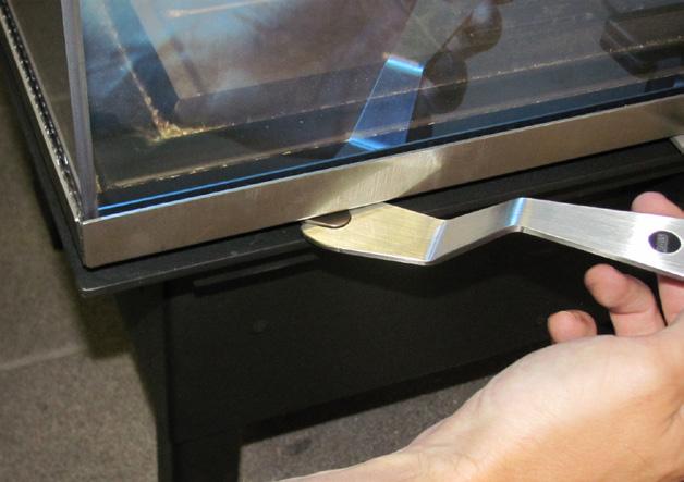
Cleaning the door glass
Lock the door in position before cleaning. Use the special key that is delivered with the wood-burning stove. Turn the lock that is positioned above the side of the door.
The side door can now be opened for cleaning by turning the locking hook in the top and bottom of the door.


Pull the side glass and clean the inside of the glasses.
Lock the side glass and release the door i reverse order. Repeat the procedure on the opposite side glass.


Cleaning the combustion chamber
Scrape/shovel the ash through the grate in the middle of the stove. The ash tray below is removed and emptied into a non combustible container until it has cooled. You can dispose of ash with your normal household waste.


REMEMBER!
• never remove all the ashes from the combustion chamber
• the wood will burn at its best with a layer of ashes of approx. 2 cm.
CLEANING THE FLUE
To gain access to the flue, remove the flue plate made from vermiculite. Next, remove the steel baffles.
Baffles
Vermiculite flue plates
Baffles
Vermiculite flue plates
Remove any dirt and dust and in reverse order, put the parts back into position.
NB!
Exercise caution when you position the flue plate and baffle.
OPERATING INTERUPTIONS
Stove is burning too strong could be caused by:
• leak around the door seal
• chimney draught too large >22 Pa, draught control regulator should be installed.
Stove is burning too weakly could be caused by:
• too small amount firewood
• too little air supply for room ventilation
• unclean smoke channels
• leaky chimney
• leakage between chimney and flue
Low draught in chimney could be caused by
• temperature difference is to small, e.g. due to poorely insulated fluepipe
• outdoor temperature is high e.g.in the summer
• no wind
• chimney is too short or is on the lee side
• false air draught in chimney
• chimney or flue pipe is blocked
• high-density housing (lack of fresh air intake)
• negative smoke draught (poor condition)
In case of cold chimney or difficult weather conditions you can compensate by adding more fresh air (open the damper) to the stove than usual.
If your stove continues to malfunction, we recommend that you contact your RAIS distributor or chimney sweep.
WARNING!
If incorrectly or too damp firewood is used, it can lead to excessive formation of soot in the chimney and possible a chimney fire:
• in this case shut off all air supply from outside (if installed) to the stove
• contact the fire department
• never attempt to put out fire with water!
• afterwards, you should ask your chimney sweeper to check the stove and chimney
IMPORTANT!
• to ensure safe burning there must be clear yellow flames or clear embers at all times.
• the firewood should not be smouldering.
If the firewood is only burning slowly without flames or is smoking, and too little air is added, unburned exhaust gasses are developed. Exhaust gasses can be ignited and explode, leading to damage to material and possibly personal injury.
Never close the air supply completely when lighting a fire.in the stove.


