TTC OPERATED BY ENSCO
orientations, and identifying information, along with the discussed methodology of how to identify the Point-of-Derailment (POD) and the first derailed car. Collecting this information is important to understand how the cars are situated in the pile up because that can provide insights into the investigation. Another hands-on session was conducting real-world inspections of thirty-two different component failures that can lead to derailments, depicted in Figure 2. An important aspect of this activity was accurately identifying defective conditions that are the cause of a derailment, rather than broken components that were caused by the derailment event. This is key to ensure accurate derailment cause finding. It’s common that at a derailment site there are lots of broken components such as broken rail and wheels. But were any of them the cause of the derailment? There are specific characteristics on a broken rail or broken wheel that caused the derailment vs. being caused by the derailment. This includes rail end batter and batter on a broken wheel. Additionally, broken wheels have additional damage on their tread from continuing to roll on the track prior to the derailment. Attendees also had the opportunity to have hands-on experience with failed component photography best practices. Many times, the field personnel are the only ones that can get critical photographs needed for the investigation. Capturing quality photographs, particularly at nighttime, can be a challenge as shown in Figure 3. Using photography best practices can make sure that important features of the fracture surface are captured so that an accurate investigation can be made. In the case of Figure 3, it is a broken weld caused by a fatigue crack initiated at the base. Often at a derailment, the broken rail is heavily damaged. But by using the method shown on the right side of Figure 3 where a flashlight was shining from the side, the features of the fracture surface stand out well, allowing a metallurgist investigator clearly to identify where the fracture surface initiated from, even if the broken rail is damaged. A unique aspect of the workshop was that it had both track and rolling stock (mechanical) attendees and both got the opportunity to experience hands-on activities that they wouldn’t normally have in their typical job duties. Figure 4 is one of these hands-on sessions which was conducting a first derailed car inspection. Attendees performed inspections on both freight and passenger railcars using all the necessary gauges and measurements to fill out an inspection form. This included using finger rtands.com
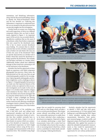
Figure 2. Attendees reviewing one of thirty-two examples of component failures that can lead to derailments.
Figure 3. At the workshop, photography best practices were incorporated into failed component hands-on inspection. Shown is a broken weld example of how lighting affects photographing a broken rail at a nighttime derailment investigation.
gauges that are needed for assessing wheel wear such as a thin flange which can play a role in a switch point derailment. This unique session allowed non-rolling stock staff to have memorable experiences to enable them to be better informed when conducting a derailment investigation. Depicted in Figure 4 are attendees performing a center bowl measurement. Issues with a center bowl are one of multiple railcar factors that can play a role in increasing lateral wheel force, which can be a contributor to wheel climb, rail rollover, and gauge widening derailments.
Similarly, attendees had the opportunity to identify a POD and take track geometry measurements at 15.5-foot stations both leading up to and following the POD. Figure 5 shows attendees making these station measurements themselves. Each participant measured gauge, crosslevel, profile, and alignment using a level board and stringline. Additionally, they applied best practices to adjust the unloaded track geometry measurements so they would be representative of loaded conditions. This was an excellent opportunity for new railway professionals to September 2025 // Railway Track & Structures 5