


GENERAL SAFETY RULES
Your PLANER has many features that will make your job faster and easier. Safety, performance and reliability have been given top priority in the design of this tool, qualities to make easy to maintain and to operate.
Carefully read the entire manual before attempting to use this tool. Make sure to pay special attention to the safety rules and indications, plus all the warnings and cautions of this manual.

WARNING: Read and understand all instructions. Failure to follow all indications listed below, may result in electric shock, fire and/ or serious personal injury.
SAVE THESE INSTRUCTIONS.
WORK AREA
• Keep your work area clean and well lit. Cluttered benches and dark areas may cause accidents.
• Do not operate power tools in explosive atmospheres, such as in the presence of flammable liquids, gases or dust. Some power tools create sparks which may provoke fire.
• Keep away observers, children and visitors while operating a power tool. Distractions can cause you to lose control.
ELECTRIC SAFETY
• Double insulation eliminates the need for the three wire grounded power cord and grounded power supply system.
• Avoid the body contact with grounded surfaces such as pipes, radiators and refrigerators. There is an increased risk of electric shock if your body is grounded.
• Don’t expose power tools to rain or wet conditions. The precense of water into power tools will increase the risk of electric shock.
• Do not abuse of the power cord. Never use the power cord to carry the tool and do not pull the plug off the outlet. Keep the cable away of heat, oil, sharp edges or moving parts. Replace damaged cords immediately. Dam- aged cords increase the risk of electric shock.
• When operating a power tool outside, use an outdoor extension cord marked “W-A” or “W”. These cords are rated for outdoor use and reduce the risk of electric shock.
EXTENSION CORDS
Replace damaged cords immediately. The use of damaged cords can shock, burn or electric shock. If an extension cord is necessary, a cord with adequate size conductors should be used to prevent excessive voltage drop, loss of power or overheating. The table below shows the correct size to use, depending on cord length and nameplate amperage rating of tools. In case of doubt use the next heavier gauge. Always use UL listed extension cords.
SIZE RECOMMEND EXTENSION CABLES

PERSONAL SAFETY

• Stay alert, watch what you are doing and use common sense when operating a power tool. Don’t use the tool if you are tired or under the influence of drugs, alcohol or medication. A moment of unattention while operating power tools may cause a serious personalinjury.
• Dress properly. Do not wear loose clothing or jewellery. Contain long hair. Keep your hair, clothing and gloves away of moving parts. Loose clothes, jewellery or long hair can be caught in moving parts.
• Avoid an accidental starting. Be sure that the switch is OFF before plugging in. Carrying tools with the finger on the switch or plug in the tool switch in ON may cause accidents.
• Remove the adjusting keys or wrenches before turning the tool on. A wrench or a key that is left close to a rotating part of the tool may provoke a personal injury.
• Do not overreach. Keep proper footing and balance at all times. Proper footing and balance enables better control of the tools on unexpected situations.
• Use safety equipment. Always wear eye protection. Dust mask, nonskid safety shoes, hard hat, or hearing protection must be used for appropriate conditions.
• Before connecting the tool to a power source (receptacle, outlet, etc.) be sure that the volt-
age supplied is the same as that one specified on the nameplate of the tool. To use a not specified voltage may cause a serious injury to the user as well as damage the tool.

IMPORTANT: This appliance is not intended for use by persons (including children) with reduced physical, sensory or mental capabilities may be different or reduced, or lack of experience or knowledge, unless such persons are supervised or trained to operate the product by a person responsible for their safety. Children should be supervised to ensure they do not use the devices as toys.
TOOL USE AND CARE
• Do not force the power tool. Use the correct tool for the application. The correct tool will do the job better and more safely at the rate that it was designed to work at.
• Use clamps or other practical way to secure and support the workpiece to a estable platform. Holding the work by hand or against your body is unestable and may cause loss of control.
• Do not use tools if switch does not turn it on or off. Any tool that cannot be controlled whith the switch is dangerous and must be re- paired.
• Disconnect the plug from the power source before making any adjustments, changing accessories or storing the tool. This preventive safety measures reduce the risk of accidental starting of the tool.
• When the power tool is not in use, store it out of the reach of children, and do not al- low individuals who are not familiar with the power tool or these instructions to operate it. Power tools are dangerous in the hands on un- trained users.
• Maintain the power tool. Check for misalignment or binding of moving parts, broken parts, and any other condition that may affect the operation of the power tool. If it is damaged, have it repaired before using. Many accidents are caused by poorly maintained power tools.
• Check for misalignment or bonding of moving parts, breakage parts, and any other condition that may affect the tools operation. If you find a damaged tool, take it to service before use it.
• Use only accessories that are recommended by the manufacturer of your model. Suitable accessories for one tool, may become hazardous when are used on another tool.
• Do not alter or misuse the tool. These tools have been built by precision. Any alteration or modification not specified is misuse and may result in a dangerous condition.
• Is recommendable to use a safety device suitable, such a thermal and diferential switch when you are using an electric equipment.
REPAIR AND SERVICE
• Tool service must be perfomed only by qualified repair personnel. Service or maintenance performed by unqualified personnel could result in a risk of injury.
• When tool service is required, use only identical replacement parts and follow the instructions from Maintenance Section in this manual. The use of unauthorized parts or failure to follow Maintenance Instructions may cause a risk of electric shock or injury.
SPECIFIC SAFETY RULES FOR INDUSTRIAL PLANERS
1. Serious personal injury may occur if normal safety precautions are overlooked or ignored. Accidents are frequently caused by lack of familiarity or failure to pay attention. Obtain advice from supervisor, instructor, or another qualified individual who is familiar with this machine and its operations.
2. Every work area is different. Always consider safe- ty first, as it applies to your work area. Use this machine with respect and caution. Failure to do so could result in serious personal injury and damage to the machine.
3. Prevent electrical shock. Follow all electrical and safety codes, including the National Electrical Code (NEC) and the Occupational Safety and Health Regulations (OSHA). All electrical connections and wiring should be made by qualified personnel only.
4. TO REDUCE the risk of electrical shock. DO NOT use this machine outdoors. DO NOT expose to rain. Store indoors in a dry area.
5. STOP using this machine, if at any time you experience difficulties in performing any operation. Contact your supervisor, instructor or machine service center immediately.
6. Safety decals are on this machine to warn and direct you to how to protector yourself or visitors from personal injury. These decals MUST be maintained so that they are legible. REPLACE decals that are not legible.
7. DO NOT leave the unit plugged into the electrical outlet. Unplug the unit from the outlet when not in use and before servicing, performing maintenance tasks, or cleaning.
8. ALWAYS turn the power switch OFF before unplugging the planer.
9. DO NOT handle the plug or planer with wet hands.
10. USE only accessories as described in this manual.
11. DO NOT pull the planer by the power cord. NEVER allow the power cord to come incontact with sharp edges, hot surfaces, oil orgrease.
12. DO NOT unplug the planer by pulling on the power cord. ALWAYS grasp the plug, not the cord.
13. REPLACE a damaged cord immediately. DO NOT use a damaged cord or plug. DO NOT use if the planer is not operating properly, or has been damaged, left outdoors or has been in contact with water.
14. DO NOT use the planer as a toy. DO NOT use near or around children.
15. ENSURE that the machine sits firmly on the floor before using. If the machine wobbles or is unstable, correct the problem by using shims or blocks prior to operation.
16. This machine is designed to process WOOD ONLY.
17. NEVER position fingers or thumbs near the infeed roller.
18. Long pieces of stock should ALWAYS be supported with some type of fixture.
19. DO NOT operate planer with dull or damaged blades.
20. MAKE CERTAIN that the planer is properly adjusted prior to use.
21. DO NOT try and remove excessive amounts of wood in one single pass.
22. INSPECT all stock before planing, ensuring that there are no foreign objects embedded in the wood, loose knots, or knots that may become loose during operation.
23. DO NOT attempt to remove jams until power is disconnected and all moving parts have
come to a complete stop.
24. MAKE SURE that there is adequate operating space on both the infeed and outfeed sides of the planer before operating.
25. DO NOT attempt to plane wood that is less than 7” long or less than 1/8-inch thick.
FEATURES
KNOW YOUR TOOL
Before attempting to use this chop saw, become familiar with all of its operating features and safety requirements.
WARNING: Do not allow familiarity with the hammer drill to cause carelessness.
Remember that a fraction of a second of carelessness is enough to inflict severe injury.
KNOW YOUR TOOL
1. MAGNETIC SWITCH.
2. RETURN ROLLERS.
3. TABLE RAISE/LOWER HANDWHEEL.
4. BED ROLLERS.
5. LIFTING HANDLES.
6. ACCESS PANEL
7. BELT GUARD.

MAGNETIC SAFETY SWITCH OPERATION
The magnetic safety switch as shown as up Fig. needs to be installed to under side of the front rail, see assembly section in this manual for further b instructions.

Do not turn the cabinet saw on until all assembly and adjustment instructions have been done. To start the cabinet saw, press the green start button (a) and to stop the cabinet saw, press the red emergency stop button (b).
UNPACKING

IMPORTANT:The machineis heavy,twopeople are required to unpack and lift. Use a safety strap to avoid tip over when lifting machine. Check shipping carton and machine for damage before unpackaging. Carefully remove packaging materials, parts and machine from shipping carton. Always check for and remove protective shipping materials around motors and moving parts. Lay out all parts on a clean work surface.
Remove any protective materials and coatings from all of the parts and the jointer. The protective coatings can be removed by spraying “Multipurpose lubricant“ on them and wiping it off with a soft cloth. This may need to be redone several times before all of the protective coatings are removed completely.
After cleaning, apply a good quality paste wax to any unpainted surfaces. Make sure to buff out the wax before assembly. Compare the items to inventory figures; verify that all items are accounted for before discarding the shipping box.
WARNING: If any parts are missing, do not attempt to plug in the power cord and turn “ON” the machine. The machine should only be turned “ON” after all the parts have been obtained and installed correctly.

a. Dust chute.
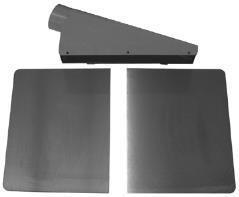
b.Extension wings (front & back).
c. Handwheel.
d. Handle.
e. M12 hex nut.
f. 13 X 28 x 3t flat washer.
g. 12-14mm open endwrench.
h1. 33mm Open end wrench.
h2. 8-10mm Open end wrench.
i. 6mm Allen Wrench.
j. 5mm Allen Wrench

k. 4mm Allen Wrench
l. 3mm Allen Wrench
m. 2.5mm Allen Wrench.

n. M6 x 12mm Hex Head Serrated Screw.
o. Knob.
p. M5x12mmHexSocHdScrew.
q. 5.2x12x2t Flat Washer.
r. Hinge Bracket Right.
s. M8 x 20mm Hex Soc Set Screw.
t.M10x30mmHexSocHdScrew.
u. M10 Lock Washer.
v. 10.2x21x2t Flat Washer.
w. Locking Foot Pedal.
x.M8 Hex Nut.
y.M8LockWasher.
z. M8 x 65mm Carriage HdScrew.
aa. M6 x 16mm Hex Soc Hd Screw.
ab. Roller.
ac. Rear Roller Bracket.
ad. Front Roller Bracket.


ASSEMBLY
Before beginning assembly, take note of the following precautions and suggestions.
FLOOR
This tool distributes a large amount of weight over a small area. Most commercial floors are appropriate for this unit, however, in residential use, flooring may need added reinforcement to accommodate the weight of the machine and operator.
WORKING CLEARANCES
Take into consideration the size of the material to be processed, space for auxiliary stands, work benches, etc. before setting up this machine. Make sure that you allow enough space for your machine to operate freely.
OUTLET PLACEMENT
Outlets should be located close enough to the machine so that the power cord or extension cord is not in an area where it would cause a tripping hazard. Be sure to observe all electrical codes if installing new circuits and or outlets.
WARNING: DO NOT assemble the planer until you are sure the tool is not plugged in. DO NOT assemble the Planer until you are sure the power switch is in the OFF position. For your own safety, DO NOT connect the machine to the power source until the machine is completely assembled and you read and understand the entire User Manual.

5. Screw handle into the threaded hole on the handwheel (Fig.2).
LOCKING FOOT PEDAL
NOTE: Assembled the locking foot pedal assembly on to the planer before remove the planer from metal pallet.

1. Loosen 4 of M6 x 10mm pan head screws remove the cabinet front cover for assembly the locking foot Pedal.
2. Use 2 of M8 x 65mm carriage head screws assembly the foot pedal on to tube mounting holes which on the front below position of cabinet.
3. Assembly both M8 lock washers and tighten the M8 hex nuts. Replace the cabinet front cover.
DUST CHUTE

WARNING:This planer is a very heavy piece of equipment. To assist with moving the unit, this Planer contains lifting handles (Fig.1a) that slide out from the base of the planer head. These handles can be used as lifting points using a forklift or overhead lift. Attempting to lift this unit without the proper equipment or adequate assistance could result in a serious injury.
HANDWHEEL
The purpose of the handwheel is for raising and lowering the planer table
1. Locate the handwheel shaft at the front right corner of the planer.
2. Insert key (Key is taped to shaft) into the keyway on the handle shaft.

3. Line up the notch in the handwheel with the key and slide the handwheel onto the handle shaft.
4. Secure the handwheel using one M12 hex nut and one M12 flat washer provided.
This planer features a 5-inch dust chute for use with a dust collection system. If this planer is not to be hooked up to a dust collection system, DO NOT attach the dust chute.
1. Assembly the dust chute on to the left hinge bracket (Fig.4a) which assembled on the back of left side of cutter head casting.

2. Assembly the right hinge bracket (b) on the right side of dust port.
3. Use 4 mm allen wrench to tight both of 2 M5 x 12 mm hex soc screws and M5 washers to secure the right hinge bracket.
4. Unbolt the upper cover from the planer to allow access to the screw holes.
5. To attach the dust chute, mount the dust chute above the upper cover on the planer.
6. Line up the 3 holes on the top of the dust chute with the 3 holes on the upper cover and fasten with three M6 x 12mm hex head serratedscrews (Fig.5d).

7. Use three M6 x 12mm hex head serrated screws and fasten the dust chute to the body of the planer.
8. Rebolt the upper cover to the planer.
9. Assembly the either side of both front / rear roller bracket (e) and do not securing the screws. NOTE: The front roller bracket should be assembled on the front side of upper cover and rear roller bracket should be on the rear side.
10. Assembly both rollers on to roller bracket then the other side of roller bracket and tighten all the screws.
11. Spin rollers (C) by hand to insure that they move freely.
SWITCH BRACKET ASSEMBLY
1. Find the hardware of 2 M6 x 16mm hex soc head screws and M6 lock washer for assembly the switch bracket on the left hand side of cutter head casting.
2. Use 5mm allen wrench and tighten the 2 of M6 x 16 mm hex soc screws(Fig.6).

GEARBOX SHAFT
KNOB ASSEMBLY
Assembly the knob on to the shaft as Fig.7 showed.

EXTENSION TABLES
The extension table support the workpiece as it enters and exits the planer.
1. To mount the extension tables, thread three M8 x 20mm set screws into the bottom holes of the extension table. Only screw them in about 1/3 of the way for now.
2. Using three M8 x25mm hex head mounting bolts, mount one extension table to the main table (Fig.8).
3. Place a straight edge on the main table so that it lies flat on the table and extends out over the extension table (Fig.9).


4. Adjust the three set screws until edge of the extension table that is the furthest away from
the main table is even with the straight edge. Please note that it may take several combinations of loosening and/or tightening the set screws and mounting bolts to get the extension table level with the main table.
5. Repeat steps 1-4 to attach the other extension table to the other side of the main table.
ADJUSTMENTS
Some of the adjustments covered in this section have already been made at the factory. It is still a good idea to familiarize yourself with all of the following procedures so that you have a solid understanding of the planers operation.
TABLE PARALLELISM ADJUSTMENT

To make adjustments to the table, it is necessary to make a gauge block. When constructing this block, be sure to use a hardwood such as oak or maple. DO NOT use standard 2x4-inch material. A diagram for this block is located near the end of the manual.
NOTICE: A substitute for this gauge block would be to use a magnetic dial indicator. Anywhere it calls for use of the gauge block in this section, you may substitute with the dial indicator.
WARNING: DO NOT make adjustments while the planer is running. Make certain that the switch is in the off position and that the machine is disconnected from the power source.
CAUTION: Planerknives are extremely sharp. Please use extra caution when your hands are near the blades.
1. Having the table parallel to the cutterhead is essential for planing stock perfectly square. Check this by placing the gauge block that you have constructed under the left end of the cutterhead.
2. Turn the handwheel clockwise to raise the table so that the block barely touches the left side of the body of the cutterhead.
NOTE: Make sure that the block is actually touching the body of the cutterhead and not the knives.
3. Slide the block to the right taking note of any gaps between the top of the block and the bottom of the cutterhead body. Measure any of these gaps with a feeler gauge.
4. When moving the block from left to right, if the block wedges tightly between the cutterhead and the table, repeat steps 2 and 3, but start from the right side of the cutterhead body and slide to the block to the left.
5. Referring back to your measurements with the feeler gauge, if the gap difference from one side to the other is .004” or less, no ad- justment will be necessary. If the gap is greater than .004, but less than .016”, proceed to step 6. If the gap is greater than 0.016, refer to the ADJUSTING CHAIN DRIVE section in the AD- JUSTMENTS section of the manual.
6. For gap differences between .005” and .016”, deternine which side of the table needs to be raised to fix the gap.
7. Loosen both sets of screws for each column on the side that needs adjusted.
8. Pull up or push down on the table in the direction that it needs to move, hold in position and retighten the screws.
9. Repeat these steps until the variance is .004” or less.
CHAIN ADJUSTMENTS
WARNING: MAKE CERTAIN THAT THE SAW IS DISCONNECTED FROM THE POWER SOURCE. The chain drive in your planer transfers movement from the hand wheel driven column to the three other support columns. The chain drive may require an adjustment to remove slack as the chain stretches over time, or as part of table leveling procedures.
CHAIN TENSION
To adjust chain tension:
1. Remove the access panel on the stand.
2. Loosen the two hex head bolts (Fig.11a) that fasten the idler sprocket (b) to the base and move the idler sprocket until excess slack in the chain has been eliminated.

3. Retighten the two hex head bolts.
4. Replace access panel.
ADJUSTING CHAIN DRIVE
NOTICE: The following steps should only be done AFTER you have gone through the TABLE PARALELLISM ADJUSTMENT section of this manual and the measurements you attained from that section are greater than .016”.

WARNING: Make certain that the saw is disconnected from the power source.
1. Remove the panel to gain access to the chain drive assembly.
2. Loosen two hex head bolts (b) that fasten the idler sprocket (c) to the base until you can turn each corner sprocket (d) independently. One of the corner sprockets is shown in Fig.11. NOTICE: If the chain drive is loosened too much, it will fall off all of the sprockets. Replacing a chain that has come off the sprockets is a very tedious process. Make sure to loosen the idler pulley just enough to allow you to be able to turn the corner sprockets.
3. Each tooth on a corner sprocket represents .016” of vertical movement as it turns.
4. Whichever end of the table is too high, turn the sprockets at that end of the table clockwise to lower the table. For example if the back end of the table is too high, the back two sprockets would need to be rotated clockwise to lower the back side of the table. If the right end of the table is too high, the right two sprockets would be rotated clockwise to lower the right side, etc.
NOTICE: Make certain, as you turn the sprockets, to keep an accurate tooth count to ensure that the table is lowered equally on a specific side.
5. Recheck Table Parallelism using your gauge block. Once the tolerance is less than .016”, replace access cover and refer back to the TABLE PARALELLISM ADJUSTMENT section in the ADJUSTMENT section of this manual.
KNIFE INSPECTION
CAUTION: Planer knives are extremely sharp. Please use extra caution when your hands are near the blades.
The planer knives are set at the factory using jack screws. Springs are also included with your planer which may be used instead of the jack screws, depending on your preference. These springs are installed beneath the knives. You can leave the springs in place as it will not affect the adjustment if they are not removed.
If you prefer to use the spring adjustment method, you will need to remove each knife, remove the jack screws, leave the two springs under each knife and replace the knife. Follow the steps below if using the spring adjustment method.
WARNING: MAKE CERTAIN THAT THE SAW IS DISCONNECTED FROM THE POWER SOURCE.
1. Move the hinged dust port and upper cover assembly to expose the cutterhead (fig.12).

2. Remove the belt guard. Turn the cutterhead (using the pulley) until the first knife is top dead center.
3. Using the knife setting gauge, check the knife height. The jig
should sit with both feet on the cutterhead. See figure 13.

If the knife is properly adjusted, the contact point at the center of the gauge should just touch the tip of the knife. If the knife does not make contact, or if the knife is high enough to
cause the legs of the gauge no to set on the cutterhead, the knives will need adjusted. Be sure to inspect all 4 knives in the same manner. The planer knives will need to be adjusted periodically and ultimately will need to be removed to be sharpened. Adjustments should be as precise as possible with tolerance within .0002”-.003”. This will help to prolong the sharpness of the knife edges. Improperly adjusted knives can cause an imbalance condition in the cutterhead and shorten bearing life, as well as produce substandard results.
4. Loosen the gib bolts by turning them clockwise until the knife is loose in the slot.
5. Carefully remove the knife.
6. Unscrew the jack screws completely from threaded hole and remove.
7. Be sure that there is one spring in each of the of the two holes in the bottom of the knife slot. See figure 14.

NOTICE: The springs DO NOT go into the threaded hole where the jack screws were installed.
KNIFE ADJUSTMENT
The knives are locked in the cutterhead with the wedge type gibs and gib bolts Spring located under the knives assist in setting the knife height. Jack screws under the knives allow fine tuning to help out in the setting process.
1. MAKE CERTAIN THE MACHINE IS DISCONNECTED FROM THE POWER SOURCE.
2. Move hinged upper cover assembly to expose the cutterhead.
3. Loosen the gib bolts until the knife is loose in the slot. The gib bolts turn clockwise to loosen and counterclockwise to tighten. See figure 15.
4. Place the knife setting jig over the knife on the cutterhead as shown in Fig 16. The feet of the jig should be securely planted on the cutterhead,


Fig.15

making sure the gauge rod remains parallel to the cutterhead. See figure 16.
5. Lower the jack screws as low as possible.
6. Maintain a steady pressure on the knife setting jig while retightening the gib bolts. The springs in the cutterhead will push up on the knife allowing for proper alignment of the knives.
7. Once gib bolts are tightened, raise jack screws until they just touch the bottom of the knife. You should feel resistance when the jack screw touches the bottom of the knife.
NOTICE: When making adjustments to the planer knives, all four knives must be adjusted the same. DO NOT adjust one knife without adjusting the others as this can result in knife damage, poor performance and possible injury to the operator.
CHIP BREAKER
The chip breaker is located on the top side of the planer and it extends down around the front of the cutterhead. The purpose of the
chip breaker is to prevent deep gouging, also known as tear-out,as the knives do their job. It works by breaking up the woodchips as they are being cut by the knives. The chip breaker also deflects and shoots out the woodchips away from the surface of the board and out the planer.
WARNING: DO NOT make adjustments while the planer is running. Make certain that the switch is in the off position and that the machine is disconnected from the power source.
1. Move the hinged upper cover assembly and lower the table.
2. Make sure that the knives are properly adjusted.
3. Place the gauge block (Fig.17a) on the table (b) directly under the cutterhead (c).
4. Rotate the cutterhead until one of the knives are at its lowest point.

5. Using a .040” feeler gauge between the gauge block and the cutterhead, raise the table until the knife just touches the feeler gauge.
6. Remove your feeler gauge and slide the gauge block under one side of the chip breaker (d). The chip breaker should just touch the top of the gauge block.
7. Slide the gauge block to the oppo- site side of the chip breaker, checking it the same way.
WARNING: Make certain the machine is disconnected from the power source.
1. Remove the hinged top cover and dust port assembly.
2. Place the gauge block (a) on the table (b) directly under the cutterhead (c).
3. Rotate the cutterhead until one of the knives are at its lowest point.
4. Loosen both locknuts (g).
5. Place gauge block under the center of the pressure bar and adjust both of the setscrews (h) until the pressure bar just touches the tip of the block.
6. Once the bar is set, retighten both of the locknuts and replace top cover and dust port.
FEED ROLLER HEIGHT
The infeed and outfeed rollers are responsible for moving the workpiece through the machine and pressing the workpiece flat against the main table.
WARNING: Make certain the machineis disconnected from the power source.
1. Lower the table so the gauge block (Fig.19a) fits under one side of the infeed roller (b).


8. If any adjustment is necessary, loosen the locknuts (Fig.18e) and turn the setscrews (f), stop turning when the chipbreaker just touches the top of the gauge block.
9. Retighten both lock nuts and replace hinged dust hood.
PRESSURE BAR
The pressure bar, like the chipbreaker, controls lumber as it passes under the cutterhead. The pressure bar helps to keep the lumber from lifting after it has been planed. Incorrect positioning of the pressure bar can result in a number of undesirable results such as snipe or chatter marks. Setting the pressure bar too low can also place excess load on the motor. To adjust the pressure bar:
2. Raise the table until the gauge block just barely touches one side of the infeed roller.
3. Push the gauge block through so that it is under the edge of one of the knives.
4. Turn the cutterhead (c) by hand using the pulley until one of the knives are in its lowest position.
5. Using a feeler gauge, check the clearance between the top of the gauge block and the edge of the knife. Clearance should be .040”.
6. Repeat steps 1-5 for the opposite side of the roller.
7. Repeat this same process for the outfeed roller, If any adjustment is necessary continue on to step 8.
8. Remove the gear box cover to access the roller adjustments on the drive chain side on the planer. One socket head cap screw holds the drive chain cover in place.
NOTE: There are two metal guard plates bolted to the backside of the gear box cover. It may be necessary to remove one of these guards in order to remove the gear box cover.
9. Loosen the roller adjustment check nuts (Fig.20d) to change the height of the roller.

10. When the roller is set in the correct position, retighten the check nuts from step 9. 11. Recheck roller height and repeat steps 8-10 if necessary.
FEED ROLLER PRESSURE
Infeed and outfeed roller pressure is an important aspect of any planer. When the workpiece is fed through the planer, the correct amount of pressure will help ensure that the board does not slip (too little pressure) or does not jam (too much pressure).
NOTICE: Excessive pressure may damage workpiece. It’s important to note that different lumber will require varying amounts of pressure, so you may have to experiment with different settings. While some rough cut lumber will go through the planer with little trouble at one pressure setting. Other pieces may have some more difficulty.
NOTICE: Adjusting the roller pressure does not affect height.

WARNING: Make certain the machine is disconnected from the power source.
1. Before adjusting roller pressure, ensure that the knives and feed rollers are set correctly.
2. Unscrew the four large pressure set screws (Fig.21a & b) on the top of the planer body.

3. Remove the springs that are in the holes left by the set screws and check for any dirt or grit, cleaning off any dirt and replace springs.
4. Screw the three regular pressure set screws (a) back in until they are flush with the top of the head casting.
5. Screw in the light pressure set screw (b) until it is about 1/4 above the head casting. The reason this screw is not tightened as much as the other three is that the feed chain helps apply the needed tension to this side of the outfeed roller.
6. Tightening the set screws down further will INCREASE roller pressure, while backing them off will DECREASE roller pressure.
BED ROLLERS
The bed rollers aid the movement of the workpiece through the planer. The height of these rollers will vary depending on the types of wood. For rough stock, the rollers should be set slightly higher to keep the lumber from dragging along the bed. For smooth lumber, the rollers should be set just above the surface of the table.
WARNING: Make certain the machine is disconnected from the power source.
1. Lay a straight edge across both of the table rollers.
2. Using a feeler gauge, measure the clearance between the bottom of the straight edge and the table. Make sure to measure in several places
3. If measurement is between .002” and.005”, the clearance is acceptable. If you do not have a measurement of .002” to .005” go to step 4.
4. Loosen the set screws located on both sides of each roller.
5. Hold the adjusting plate (C), turn the eccentric shafts toadjust the roller height up or down as shown in Fig.22.

6. Repeat steps 1-5 until clearance is .002” to .005”.
7. Retighten all set screws.
8. Spin rollers by hand to ensure that they move freely.
CHIP DEFLECTOR
The chip deflector (Fig.23a) is the plas- tic plate under the top cover that keeps woodchips from falling onto the outfeed roller.

WARNING: Make certain the machineis disconnected from the power source.
1. The beveled edge of the deflector should be about 1/8-1/4 from the knife edge. Check this by care- fully rotating the cutterhead by hand
to gauge the distance between the chip deflector and the knives.
CAUTION: If the chip deflector is set too close to the knives, the rotating cutterhead may pull it in and destroy it.
2. If adjustment is necessary, loosen the three deflector mounting bolts.
3. Make sure the beveled edge of the deflector faces the cutterhead.
4. Move the deflector until the edge is approximately 1/8-1/4 from the edge of theknives.
5. Push down on the deflector with a wooden stick and spin the cutterhead by hand to ensure that it does not contact the knives.
CAUTION: Planer knives are extremely sharp. Please use extra caution when your hands are near the blades.
6. Retighten the chip deflector mounting bolts and remount the upper cover and dust port to the planer.
ANTI-KICKBACK FINGERS
2. If pulleys are out of alignment, loosen the bolts the pulley can be adjusted as wall as moving the motor mount bracket.
3. Adjust the motor position until the pulleys are aligned.
4. Retighten all bolts.
BELTS
WARNING: Make certain the machine is disconnected from the power source.
1. If the belt is too loose, remove the belt guard using the two threaded knobs.
2. To check belt tension, squeeze the Belts at their midpoint with moderate finger pressure. You should be able to deflect each belt no more than 3/4.
3. Remove the panel at the back of the ma- chine stand to access the motor assembly.

Anti-kickback fingers (Fig.24a) are an added safety feature on this planer. They are suspended from a rod that hangs across the front of the cutterhead casting. These fingers should be inspected regularly, ensuring that they swing freely and easily.
WARNING: DO NOT apply any oil or other lubricant to the antikickback fingers as this can attract dust and restrict the free movement of the fingers. This could result in damage to the planer, the workpiece, or even serious injury to the operator or others in the work area.
DO NOT attempt to use the planer if the antikickback fingers are not functioning properly.
PULLEYS
WARNING: Make certain the machine is disconnected from the power source.
1. To inspect pulleys, place a steel ruler or other type of straight edge across the pulleys to check the alignment. If the ruler crosses them evenly, the pulleys are aligned correctly.

GEAR BOX

4. The motor pivots on a platform suspended at one end by two threaded adjustment bolts. Adjust the locknuts (Fig.26a) up or down the shafts until the desired belt deflection is achieved.
The gearbox is located just behind the handwheel on the right side of the planer. The gearbox transfers power from the belt driven cutterhead to the power feed rollers. It has a two speed transmission that is controlled by a lever on the right side of the planer. When it is engaged, the power feed rollers will move the workpiece through the planer at either 16 ft/ min or 30 ft/min. The center position on the lever is neutral.
1. To inspect gearbox, loosen the socket head cap screw on the gearbox cover.
2.Pullthecoverofftheroll pinsthat hold itin place. NOTE: There are two metal guard plates bolted to the backside of the gear box cover. It may be necessary to remove one of these guards in order to remove the gear box cover.
3. Inspect the bolts that hold the sprockets in place.
4. Check the drive chains to make sure that the retaining clips are in place(Fig.27).

OPERATION INSTRUCTIONS
WARNING: This planer is a very powerful woodworking machine designed and built for professional use.
Because of this, the machine should be operated with significant care and caution. Failure to do so could result in severe injury to the operator or others in the work area. Be sure to read this entire manual for all safety precautions before operating this machine.
PLANER SUMMARY
1. Examine all lumber carefully for defects such as twisting, warping, knots, splits, crossgrain, and foreign objects such as nails, staples, etc before running it through the planer. If you are unsure about the quality of the wood, DO NOT USE IT!
2. Use the full width of the planer. Alternate between the left, right, and center when feeding lumber through the planer. Doing so will help extend the life of your blades.
3. Be sure to clean off all glue of joined boards before planning.
4. This planer is designed for natural wood only. DO NOT use any composites, laminates, particle board, plywood, or plastics in the planer.
5. ALWAYS plane with the grain of the wood. NEVER feed end cut or end grained lumber through the planer.
6. When making multiple passes through the planer on long stock, use the stock return rollers located on top of the machine to move the workpiece over to the infeed side of the table.
7. Wood that has a high moisture content (greater than 20%) or wood exposed to rain or snow will plane poorly and cause excessive wear to the knives, and accelerate rust and corrosion.
8. This manual does not cover every aspect of planning wood. You should research alternative publications for more specific requirements. This type of follow up will help provide with a better understanding of the planning process as well as alert you to several precautions to take that may or may not be listed in this manual.
POWER FEED
The power feed features two different feed rates, 16FPM (feet per minute) and 30FPM.
WHILE THE MACHINE IS RUNNING, moving the knob one direction produces the 16 FPM setting while moving the other direction produces the 30FPM setting. There is also a central position for the knob, which is neutral (Fig.28).
CAUTION: The feed rate should be set ONLY while planer is running, and BEFORE the workpiece is inserted into the planer.
DO NOT attempt to change speeds after the cutting operation has started.

DEPTH LIMITER
This planer is equipped with a depth limiter (Fig.29a), located at the bottom of the cutterhead casting, which controls the maximum depth of cut to 1/8”.
With the limiter installed, you will not be able to cut more than 1/8” in a single pass. While it is possible to plane as much as 1/8” at a time, it is not recommended. Taking more shallow passes will improve the quality of your work as well as extend the life of your planer.
NOTICE: To avoid mechanical damage to the planer, do not remove the depth limiter.
HANDLE WHEEL
Turning the handwheel clockwise will raise the main table while turning it counterclockwise will lower the table. Crank the handwheel to raise or lower the table according to the desired workpiece thickness.
TRIAL RUN
Once all the assembly is complete and the adjustments are complete, it’s time for a test run.
1. Turn on the power supply.
2. Press the start button. Keep your hand near the switch, ready to shut the machine down quickly in case anything does not sound right or if there appears to be a problem.
3. The planer should run smoothly with little to no vibration or rubbing noises. If any strange noise is noticed, shut down machine and recheck all adjustments.
WARNING: Do not attempt to make adjustments while the machine is running. Make certain the machine is disconnected from the power source and the machine has come to a complete stop.
WARNING: ALWAYS wear eye protection. Any machine can throw debris into the eyes during operations which could cause severe and permanent eye damage, everyday eyeglasses are NOT safety glasses. ALWAYS wear safety goggles (that comply with ANSI standard Z87.1) when operating power tools.
MAINTENANCE
Make a habit of inspecting your planer each time you use it. Check the following conditions and repair or replace as necessary.
1. Worn Switch.
2. Damaged cords and/or plugs.
3. Damaged belts.
4. Loose bolts.
5. Any other condition that could hamper the safe operation of the machine.
TABLE
The table and other non-painted surfaces on the planer should be protected against rust. Be sure to wipe the table clean after every use. This will help prevent moisture from the wood condensing on the bare metal table. It is also a good idea to use a paste wax on the bare metal surfaces. This will help keep moisture from the table and hence help keep it from rusting. Over time, some rust may still develop on the table. To get rid of the rust, use some WD-40 and a fine steel wool.
LUBRICATION BEARINGS
Your planer is equipped with factory sealed bearings requiring no lubrication. If the bearing should fail, the planer will produce a pronounced rumble that will get even louder under load. If it is allowed to get worse, overheating can occur and eventually the bearing can seize up, possibly causing damage to other parts of the machine.
WORM GEAR
The worm gear should be inspected monthly and lubricated with a white lithium grease as needed. Remove the worm gear box to inspect.
CHAIN
The table height adjustment chain should be inspected regularly and lubricated as needed. Lubricate with a general purpose grease.
GEAR BOX
Gear box oil should be drained after the first 20 hours of operation. Replace with 80W-90 gear oil for use in room temperature shops and 50W gear oil for unheated winter shops. Inspect levels periodically and change yearly for occasional use, more frequently with heavy use. To inspect oil level:
1. Using the short end of a hex wrench, dip the wrench inside the fill hole and rotate so the long end of the wrench is parallel to the table.
2. Remove the wrench. If the end of the hex wrench is coated with oil, then the gearbox level is okay.
3. If the end of the hex wrench is not coated with oil, then you need to add more oil.
4. Remove gear box cover. For information on removing gear box cover, refer to the gear box section in the ADJUSTMENTS section of this manual.
5. Replace fill plug when finished.
DRIVE CHAIN
The drive chain should be inspected and lubricated monthly using a general purpose grease.
FEED ROLLER
The infeed / outfeed pressure setscrews double as the lubrication ports for the rollers. Add 1-2 drops of light machine oil to all ports before every use. Daily lubrication of feed rollers is CRUCIAL to the operation of the planer. Lubricate before start up.
LEAD SCREWS
The four lead screws (Fig.30a) should be lubricated with general purpose grease at least one a week.

TROUBLESHOOTING
This section covers the most common processing problems encountered in planing and what to do about them. Do not make any adjustments until planer is unplugged and moving
parts have come to a complete stop. See the section on Wood Characteristics for additional troubleshooting information.
MOTOR WILL NOT START
Low voltage. Check power line for proper voltage.
Open circuit in motor or loose connections. Inspect all lead connections on motor for loose or open connections.
MOTOR WILL NOT START; fuses or circuit breakers blow
Short circuit in line cord or plug. Inspect cord or plug for damaged insulation and shorted wires.
Short circuit in motor or loose connections. Inspect all connections on motor for loose or shorted terminals or worn insulation.
Incorrect fuses or circuit breakers in power line. Install correct fuses or circuit breakers.
MOTOR OVERHEATS
Motor overloaded. Reduce load on motor. Air circulation through the motor restricted. Clean out motor to provide normal air circulation.
MOTOR STALLS (resulting in blown fuses or tripped circuit)
Short circuit in motor or loose connections. Inspect connections on motor for loose or shorted terminals or worn insulation.
Low voltage. Correct the low voltage conditions.
Incorrect fuses or circuit breakers in power line. Install correct fuses or circuit breakers. Motor overloaded. Reduce load on motor.
MACHINE SLOWS WHEN OPERATING
Feed rate too fast. Change speed. Depth of cut great. Reduce depth of cut.
LOUD, REPETITIOUS NOISE COMING FROM MACHINE
Pulley setscrews or keys are missing or loose. Inspect keys and setscrews. Replace or tighten if necessary.
Motor fan is hitting the cover Tighten fan or shim cover.
V-belt is defective. Replace V-belt.
MACHINE IS LOUD WHEN CUTTING, OVERHEATS OR BOGS DOWN IN THE CUT
Excessive depth of cut. Decrease depth of cut. Knives are dull. Sharpen knives.
INFEED ROLLER MARKS ARE LEFT ON THE WORKPIECE
Depth of cut too shallow. Increase depth of cut.
OUTFEED ROLLER MARKS ARE LEFT ON RIGHT SIDE OF WORKPIECE
Too much spring tension on feed roller. Refer to Feed Roller Pressure section for adjustment.
CANNOT CONTROL SNIPE
Long or heavy board sags as it enters and exits. Lift up on unsupported end of board as it enters and exits cutterhead.
MACHINE HOWLS ON STARTUP
Chip deflector too close to the cutterhead. Move chip deflector back 1/8” to 1/4” from the cutterhead.
TABLE MOVES DOWN WHILE CUTTING
Knives or tip dull. Replace knives/tips.
TECHNICAL DATA
VOLTAGE-FREQUENCY
PLANING CAPACITY
FEEDING SPEED
MOTOR SPEED
POWER
WEIGHT