

Dear customer:
Sincerely thank you for using the woodworking machinery series products produced by our company.
The machine you purchased may differ from this manual in some details, but as long as you adjust the operation according to the provisions of this manual, it will not affect the safe operation of the machine.
This machine is carefully designed and manufactured by our company with excellent quality. Ensuring the safe operation of machines and the personal safety of operators is one of the important principles of our company's design. If it is operated correctly, it can ensure safe production.
The machine must be operated by trained and responsible personnel with professional knowledge according to regulations. Otherwise, there may be danger. Our company is not responsible for the losses caused by operation errors.
To help you use this machine safely and correctly, please read this manual carefully before installing and using this machine.
1. the use and characteristics of machine tools
This machine tool is a new generation of four-sided woodworking planer developed by our company according to the market research, the opinions of users and the advantages of similar products at home and abroad. The machine tool has compact structure and convenient adjustment and operation. It is mainly used for processing wood products such as wood squares, wooden boards, decorative wood line, wooden floors, etc. It is the key equipment of enterprises such as construction forestry and furniture manufacturing.
This machine can't be used to process light metals (copper, aluminum) and woodbased composites (wood-cement).
2. Contact
Regarding the working failure of the machine, the customer should tell us the following information:
1) machine model 2) machine ex-factory number
3) Voltage and Frequency 4) Purchase Date
4) Detailed information about work failure
5) Detailed information on actions to be performed on the machine
6) Working hours every day
We reserve the right to update the machine without any notice.
3. Working environment of electrical equipment
3.1 The ambient air temperature is-5 C ~+40 C, and the average value within 24 hours is not more than 35 C. 。
3.2 Altitude: The altitude of the installation site shall not exceed 2000m.
3.3 Atmospheric conditions: the relative humidity of the air at the installation site shall not exceed 50% at the highest temperature of+40 C, and higher relative humidity may be allowed at lower temperature, for example, it shall reach 90% at+20 C, and necessary measures shall be taken in consideration of condensation on products due to temperature change.
3.4 Pollution grade: Grade 3.
3.5 Impact vibration: The product should be installed in a place without obvious shaking, impact and vibration.
3.6 The external magnetic field of the installation site shall not exceed 5 times of the geomagnetic field in any direction.
4. dust collection system
4.1 After installation, the machine should be connected to the dust collection system.
4.2 Do not use the machine in the open air.
4.3 The machine is designed for industrial use.
4.4 Do not use the machine in explosive environment.
4.5 dust collection system air volume is greater than 5M3/s and wind speed is greater than 35-45m/s.
5. Residual △ ! risks
Don't forget that any machine may be potentially dangerous. Definite safety depends on you. The machine will be equipped with appropriate protective covers to ensure the safety of operators. If they are used and maintained, the protective covers are effective. Even if the safety plan is maintained and the use of the machine complies with the regulations, the following risks may rise in this operation manual: the tool of the machine rotates or stops, the risk caused by the wrong working position of the operator, the wrong fixing of the tool accessories, the wrong electrical connection, the different rotating direction of the tool, the flash caused by overheating of the parts, the possibility of contact with the tool when correcting the tool, the rotating parts (belt, pulley, chain, tool, etc.), and the powder working without inhalation. The rebound of wood processing sawdust
may hit the human body.
6. Training of operators
Trained machine operators shall use and adjust the machine, and the machine operators shall carefully read this operation manual and pay special attention to safety regulations. In particular:
6.1 Before the machine tool is repaired, adjusted and installed, the power supply must be cut off, so that all moving parts can be completely stopped and carried out by professionals.The work of electrical system must be carried out by electricians.
6.2 The operator must abide by the maintenance procedures of machine tools and safe operation procedures of machine tools.
6.3 It is strictly forbidden to disassemble any parts on the machine when the machine is running or when it is not completely stopped.
6.4 Choose the right tool.
6.5 Before shipment, it is necessary to comprehensively check whether each cutter shaft, guide rail and each adjustment part are locked and whether the blades are loose. Manually check whether each cutter shaft rotates freely, and then start the machine.
6.6 Please idle the handle of stepless speed change mechanism at high speed and low speed several times after starting each shift to prevent rusting. It is forbidden to turn the handle when stopping the machine.
6.7 Before starting up every day, check whether all safety devices are reliable. The danger of machine operation should be notified to the operator to effectively prevent the danger, and the safety should be tested regularly.
Important matter: the main power switch can only be turned on or off by approved operators
7. Safety regulations:
7.1 The operator must read the instructions carefully before starting the machine.
7.2 Read the warning signs pasted on the machine carefully.
7.3 Designate the only operator to use the machine.
7.4 Effective training should be given to the operators regarding the risks and precautions of machine use.
7.5 Operators should be trained to periodically check the safety and protective cover of the machine. If there is any fault in the safety protection device of the
machine, it should be repaired or eliminated immediately. It is strictly forbidden to start the machine with imperfect safety protection device.
7.6 When the machine is running and does not stop completely, it is forbidden for the operator to leave the job.
7.7 It is strictly forbidden to touch the parts and components that are running or not completely stopped.
7.8 This machine has been manufactured to ensure the highest safety and best performance.
7.9 It is forbidden to stand at the front end of the wood being sent to the machine.
7.10 The manufacturer is not responsible for compensation for damages caused by modifications made to the machine.
7.11 If you are under the influence of alcohol, drugs and medicines, please do not use the machine.
Safety depends on you, please don't forget that any machine may be dangerous.
8. Personal safety
8.1 Before you start, you have read this manual. Please observe carefully before feeding. Your eyes are the best safety device.
8.2 Operators shall wear protective glasses, masks, hearing protection articles and other labor protection articles, and shall not wear too loose clothes, watches and jewelry, with long hair tied in the hat. It is recommended to use shoes designated by all countries to avoid accidental personal injury.
Before starting work, you must have the following ways to protect yourself:
A) the leather apron protects itself.
B) Glasses or other appropriate protection for your eyes,
C) mask is a practical method to resist dust inhalation.
D) Adopt appropriate methods for ear protection,
E) gloves are a good way to handle sharp objects.
F) Shoes are reinforced with iron sheets and rubber soles.
9. Machine safety
9.1 All lubricating points of the machine must be lubricated before starting up.
9.2 The machine tool must have reliable grounding (there is a grounding terminal sign in the distribution box).
9.3 Select the width of the feeding wheel suitable for the width of the workpiece,
and adjust the height and proper pressure of the feeding wheel.
9.4 The processed wood shall be free of hard objects such as nails, sandstone, etc., and other articles shall not be placed on the machine countertops and other countertops.
9.5 Pay attention to the sound and operation of the motor, and prevent the operation without phase. If there is any abnormal situation, stop the machine immediately to find an electrician for maintenance.
9.6 When cutting wood with saw blade, it is necessary to install anti-backlash (backward) device to prevent wood from flying out and hurting people.
9.7 During the machining process, the feeding roller shall not be adjusted upwards, otherwise the workpiece may rebound and fly out.
9.8 All cutting tools are opposite to the direction of wood, and may not be changed by themselves, otherwise, wood may fly out and hurt people.
9.9 Pay attention to the balance state of the cutter shaft. It is strictly forbidden to install unbalanced cutters on the cutter shaft and clamp them well.
9.10 Be very careful about any action during work, and regularly check the protective cover and safety equipment.
All protective covers have been fixed and effective, otherwise, it is not allowed to start working.
9.11 Before starting, make sure that there are no sundries (tools, spare parts, etc.) on the countertop.
9.12 When installing tools, install the correct working direction.
9.13 When installing tools, the tools and parts related to tool clamping must be clean.
9.14 Do not use deformed tools, and pay attention not to exceed the speed limit indicated by the tool manufacturer.
9.15 All suction ports must be connected with dust collection system, and confirm that the dust collection system has been opened before starting work.
9.16 Adjusting the inspection machine with tools may be carried out without a protective cover.
9.17 When the machine is running, don't try to remove waste or parts from the work area.
9.18 After the machine rotates for a certain period, the belt will relax, so it is necessary to stop the machine and tighten the belt.
9.19 regularly remove sawdust, in order to prevent fire.
9.20 The machine is firmly fixed on the ground.
9.21 Pay attention to the cleanliness and protection of the relevant safety signs and operation tips attached to the machine, and update them when they are ambiguous.
9.22 Do not process wood that is too large or too small.
10. Work area safety
10.1 Keep the workplace clean and sanitary. Stacked articles shall not affect the operator's line of sight, and shall not occupy the passage.
10.2 all parts of the machine shall be cleaned of dust after each shift, and dust shall be removed once a week in the electrical cabinet (conducted by electricians).
10.3 The working area should have good lighting and sufficient space, so that the operator is always outside the dangerous area.
10.4 Good ground level prevents the danger of waste and debris falling down.
10.5 Only approved operators can stay in the work area.
10.6 Operators cannot stay on the track where sawdust and knives bounce and spray. If this track is another working area (another machine) or another channel, a barrier with complete protection should be installed immediately.
11. Maintain safety
Don't think that the electricity has been cut off during maintenance, check it yourself!
11.1 For any adjustment or disassembly of the machine, turn the main switch to OFF position and indicate it with a sign.
11.2 A has a hidden button, which can be pulled out with a lock
Lock, the key is kept by the designated operator, Cleaning and maintenance can be done in this way to prevent it from It is dangerous for its personnel to operate the main switch.

11.3 clean and remove any protective cover on the machine A Before maintenance, the machine must be completely stopped.
11.4 The cleaning and maintenance operation of the machine (especially the table
top) and the surrounding ground is an important safety factor.
11.5 Use suitable gloves when loading and unloading tools.
11.6 The cutter needs regular maintenance, and spare parts should be used to replace it.
11.7 For any failure of the machine, protective cover and cutting tools, appropriate measures must be taken immediately.
11.8 regular cleaning and maintenance work, remove sawdust and dust to avoid fire danger.
12. Machine tool parameters
Right
Left vertical axis
Front
13, warning marks (must be protected, can't sample)


13.2


14. operation panel

1. Switch lock of operation panel 2. Start and stop of front lower shaft 3. Start and stop of right vertical shaft
4. Start and stop the left vertical shaft (green start and red stop) 5. Start and stop the upper shaft
6. Continuous feeding and stop buttons 7. Push buttons before and after feeding
8. Up and down buttons of feeding wheel 9, power indicator light 10 and overload indicator light
11. emergency stop button 12. frequency control knob
15. Installation of the machine
15-1 Lifting and Unloading of Machines
Remove all spare parts for transportation and packaging before unloading. When unloading and transporting the machine, the forklift should be used to fork from the bottom of the machine.To prevent forklift fork to the machine cable and
other parts that will cause damage to the machine.Pay attention to the balance of the machine tool during unloading and handling to prevent the machine tool from toppling over.
△ ! Make sure the forklift is suitable and safe.
Sudden transportation of the machine should be avoided during lifting, and it is forbidden to stand under the machine after lifting and during transportation.
15-2 installation and horizontal adjustment
A) before the packaging of the machine is opened, the installation position shall be determined, which shall have good lighting, sufficient space (at least 500LUX), suitable power cord and dust collection system.
B) The machine tool shall be placed on a solid concrete floor. Thickness of concrete shall not be less than 150mm. Put a 10mm-thick steel plate 3 under the threaded hole of the bed foot, adjust the bolt 1 to keep the level of the machine tool within 0.2/1000mm, and finally tighten the nut 2.

15-3 electrical connection and grounding
Electrical connection and testing shall be carried out by skilled electricians to ensure that the company's power system can meet the power requirements of machines. Check that the voltage of transmission trunk line is consistent with the machine. Check the direction of the saw shaft after turning on the power supply. Because the machine is equipped with a phase sequence relay, if the phase sequence of the wiring does not meet the requirements of the machine, each shaft of the motor will not be started. At this time, the power supply should be turned off
and the position of the two-phase line should be changed. After the machine can start normally, check the rotating direction of the cutter.
15-4 connection of dust collection system
△ ! For the safety of operators, the machine must be connected to the dust collection system.
When working, the dust collection system is always open, and the exhaust pipe is connected with the dust collection system with a hose with appropriate diameter (if it is plastic hose, they must be made of incombustible materials). The diameter of the exhaust pipe is φ145mm. The normal operation of the dust collection system will properly suck away dust to ensure work safety and reduce risks. Other factors to reduce dust emission in working environment:
-maintenance of tools, machines and dust collection system
-Appropriate cutting speed and feeding speed
-Appropriate adjustment of exhaust pipe and protective cover
-Proper use of dust protection devices.
16. Machine tool operation
16.1.1 Adjust the height of the lower cutter shaft (up and down) (see Figure 1)

(Figure 1)
1. Lower knife shaft lifting handle. 2. Lock the handle for lifting the lower cutter shaft. 3. Right vertical shaft lifting handle. 4. Lateral adjustment handle of right vertical shaft. 5. Right vertical lifting locking handle. 6. Left vertical shaft lifting locking handle. 7. Horizontal adjustment handle of left vertical shaft. 8. Left vertical shaft lifting handle. 9. Upper knife shaft lifting locking handle.10. Upper knife shaft lifting handle. 11. left vertical shaft transverse locking handle 12. right vertical shaft transverse locking handle
Loosen the locking handle 2 first, then turn it 1 with a special wrench, and the front lower cutter shaft will move up and down. Place a cutter adjusting ruler on the workbench behind the cutter (see Figure 2), let the blade contact with the cutter adjusting ruler, and then turn the cutter shaft by hand. When slight friction contact is felt, the adjustment is completed, and finally the handle 1 is locked. Note: In order to eliminate thread clearance, when adjusting the height of each cutter shaft, it must be raised from bottom to top, and locked when it is in place. In case of downward adjustment, first reduce the excessive amount and then rise to the required height.
16.1.2 axial (fore and aft) adjustment (see fig. 2)

Loosen the locking bolt 2 first, turn the screw rod 3, and the cutter shaft moves transversely. After adjustment, lock the bolt 2, lean against the small backup plate 1 with the adjusting ruler, and turn the cutter shaft by hand. When the trimming knife 5 feels slight frictional contact with the adjusting ruler, the trimming knife is
flush with the small backup plate and adjusted. When the machine tool has no small backing plate, there is no need to decorate the edge knife.
16.2.1 front workbench adjustment (see fig. 3)

(Figure 3)
2
Turn the handle 3 and move the front workbench 2 up and down to form the cutting amount of the first lower planer. Tighten the handle after adjustment.
16.2.2 Adjustment of the front backup plate
Turn and move the handle 4, and the front guide plate 1 will move back and forth to form the feeding amount of the right vertical planer. After adjustment, tighten the handle 3. Adjust the distance between the front backup plate and the small backup plate 4 according to the bending degree of the wood (see Figure 4), and the distance between the small backup plate and the guide plate 3 behind the right vertical knife is 0.5 (which is generally adjusted when leaving the factory). When there is no small back plate, directly adjusting the offset distance between the front back plate and the back back back plate 3 is the cutting amount, and at this time, there is no need to decorate the side knife. The panel 2 can be moved to accommodate cutters with different diameters.

(Figure 4)
16.3 adjustment of right vertical cutter shaft (see fig. 5)
Tool

(Figure 5)
16.3.1 axial (fore and aft) adjustment
Lean against the rear guide plate with the cutter ruler to make the blade contact with the cutter ruler (see Figure 5), and then turn the cutter shaft by hand. When slight friction contact is felt, the position has been adjusted. Loosen the locking handle 3 (see fig. 1) and turn the adjusting lever 14, so that the right vertical cutter shaft can move axially. After adjustment, lock the handle 3.
16.3.2 Height (up and down) adjustment (see Figure 1)
Loosen the locking handle 15, turn the adjusting lever 2, and the knife shaft will move up and down. After adjustment, lock the handle 5.
16.4 Zuo Li cutter shaft adjustment (see fig. 1)
16.4.1 axial (fore and aft) adjustment
Loosen the locking handle 12, turn the adjusting lever 4, and the left vertical shaft
can move axially. After adjustment, lock the handle 12.
16.4.2 Height (up and down) adjustment
Loosen the locking handle 13, turn the adjusting lever 5, and the knife shaft will move up and down. After adjustment, lock the handle 13.
16.4.3 Adjustment of pressing devices on both sides of Zuo Li cutter shaft (see Figure 6)

(Figure 6)
The baffle plate 1 located behind the cutter is leveled with the blade of the cutter with a cutter adjusting ruler, and the position of the pressure plate 2 and two pinch rollers 3 in front of the cutter should be 3mm less than the distance between the blade and the backup plate. Baffle 1 and platen 2 should be as close as possible to the cutter to improve the machining quality. Adjust the cutter shaft to the required processing width after adjusting the upper and lower pressing devices and both sides of the cutter shaft.
16.5 adjustment of upper cutter shaft
16.5.1 Height (up and down) adjustment (see Figure 7)
Loosen the locking lever 2 and rotate the lifting lever 1 to realize the height adjustment of the upper cutter shaft.
Note: In order to eliminate thread clearance, when adjusting the height of each cutter shaft, it must be raised from bottom to top, and locked when it is in place. In case of downward adjustment, first reduce the excessive amount and then rise
2 o to the required height.
(Figure 7)
16.5.2 axial (fore and aft) adjustment
(see fig. 8) loosen the locking bolt 1 and turn the adjusting rod 3 (see fig. 7), so that the cutter shaft can move axially.
16.5.3 Adjustment of front and rear platen devices 1

Figure 8
(see fig. 9) front platen: loosen the bolt 7, turn the handle 5, adjust that the lowest end of the front platen 8 is about 3mm lower than the blade, and turn the screw 6 to adjust the spring pressure of the front platen. Rear platen: Turn the handle 4, and the rear platen can move up and down. After adjustment, the bottom of the
rear platen 1 is about 1mm higher than the cutter ruler. The front and rear pressure plates 1 and 8 can be adjusted to approach or move away from the cutter according to the diameter of the cutter 2. Keep the platen as close to the tool as possible.

9
16.7 table roller adjustment (see fig. 10) on

(Figure 10)
Two sets of driving rollers are installed in front of and behind the machine table, and their adjustment is carried out on the back of the machine bed. Nut 2 is used to adjust the roller height, and screw 1 is used to lock after adjustment. Generally, the front roller (tooth roller) is 2 ~ 3 mm higher than the table top, and the rear roller (smooth roller) is 0.05 ~ 0.1 mm higher than the table top.
16.8 adjustment of feeding system
16.8.1 adjustment of feeding roller
The feeding roller 1 can move on the shaft, and it is usually pressed against the middle of the workpiece (see fig. 11) to improve the machining quality. The lifting feeding roller is lifted to adapt to the work with different thicknesses. Each feeding roller can be independently adjusted up and down. Loosen the lower nut of the cylinder rod and turn the cylinder rod.
(Figure 11)
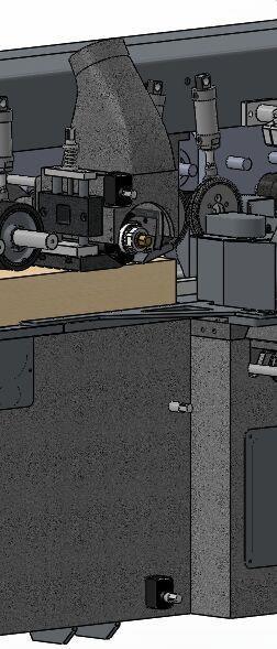
16.8.2 Pressure adjustment of feeding system
The air source triple piece located at the front lower end of the machine tool is provided with a black knob (see Figure 12), and the total feeding pressure and cots pressure can be adjusted by pulling up and rotating the knob. Pay attention to regularly inject lubricating oil into the oil cup, and regularly discharge the water in the water storage cup. Adjust knob 1 in fig. 13 to adjust the pressure of the first and second groups of feeding wheels, and adjust knob 2 in fig. 13 to adjust the pressure of the third, fourth, fifth and sixth groups of feeding wheels. General air pressure is not less than 0.4MPa
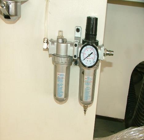
Figure 12
17 lubrication of the machine

Figure 13
17.1 The lower left side of the machine is equipped with a manual lubricating pump, as shown in Figure 14. Manual pump oil can lubricate two countertops.
Figure 14

17.3 Lubrication and Maintenance of Machine Tools
Regularly lubricate the oil filling points according to Table 2. Always keep the appearance of the machine tool clean and the guide rails of all moving parts clean.
Lubrication part
Recommended lubricating oil varieties Lubrication cycle
Outer diameter of each spindle cylinder Engine oil N46 Once in class three
Horizontal shaft lifting screw rod and screw nut Engine oil N46 Once in class three
Horizontal shaft lifting guide rail Engine oil N46 Once in class three
Vertical shaft lifting screw rod and screw nut Engine oil N46 Once a week.
Vertical shaft lifting thrust bearing Calcium grease ZG-3 Once every six months
Screw nut of screw rod after vertical shaft advancing and retreating
Vertical shaft guide rail
Vertical shaft advancing and retreating thrust bearing
Front guide plate connecting rod shaft
Feeding lifting column
Feeding lifting worm gear box
Feeding speed reducer
Pin shaft of feeding roller
Pin shaft of front platen of left vertical knife
Upper horizontal shaft front platen pin shaft
Upper horizontal axis rear platen guide rail
18. Replacement of cutting tools
Engine oil N46 Once a week.
Engine oil N46 Once in class three
Calcium grease ZG-3 March once
Engine oil N46 Once in class three
Engine oil N46 Once in class three
Industrial gear oil N460 Once a year.
Industrial gear oil N460 Once every 4000 hours
Engine oil N46 Twice in one class
Engine oil N46 Once in a class
Engine oil N46 Once in a class
Engine oil N46 Once in a class
18.1 Each cutter shaft is equipped with a shield, which is provided with danger signs and cutter rotation direction. The cutter orientation is installed as indicated schematically on the shield. Appropriate gloves should be worn on both hands when installing the cutter to prevent the hands from being scratched by the cutter.
18.2 Before changing the cutter, press the emergency stop button, and the machine must stop completely before opening the cover door, and lock the switch lock of 5 operation panel in Figure 14.1 to the control circuit. The key should be kept by the operator. Turn the main power switch to the OFF position.
18.3 Check whether the cutter is sharp and remove all dust from the cutter. The machine is equipped with many washers at random. All dust should also be removed before gasket assembly.
18.4 Use special tools equipped with this machine to load and unload cutting tools.
19. machine cleaning
Daily machine cleaning can prolong the service life of the machine and is an
important safety factor. Here are some regulations. We should properly vacuumize and clean every night:
1) Table top, back plate and all cavities (as shown in Figure 17 and Figure 18, table top, back plate, etc.)
2) Clean all movable parts and components exposed to dust every week.
Figure 17

20. Inspection of safety devices
18

-The safety device of the machine should be effective at all times, and the emergency stop button should be checked every two weeks: if any emergency stop button is pressed under normal operation of the machine, all driving devices can be stopped immediately.
-every 2 weeks, check whether the travel switches are effective and whether the push-button switches are effective.
-Regularly check whether the protective devices are effective.
-The technician in charge of inspection shall inform which areas have been inspected and the inspection results.
21. state of emergency
If the room where the machine is installed is flooded, the power should be cut off immediately. Before starting work again, the machine must be tested by skilled technicians.
In case of fire, the power should be cut off immediately, and a fire extinguisher should be used to spray the flame. Before starting work again, the machine must be tested by skilled technicians.
To be precise, the safety regulations are that there are no obstacles in the working
area around the machine, so that even if danger occurs, the operator can leave safely. Machines cannot be used in explosive rooms.
22. belt tension
After the machine is used for one cycle or many working hours, the belt will relax.
At this time, it will be necessary to tighten the belt, which will increase the stopping time of the machine. The best tension is to apply a force of 3kg in the middle of the belt, and you get a bend of about 5 mm.
Tension shall be carried out according to the following items:
1) Stop the machine, turn the main power switch to OFF position, and lock it with a lock. The key is kept by the operator, and the information being maintained is hung here.
The upper shaft and the lower shaft directly loosen the bolts for fixing the motor, tension the belt by the self weight of the motor, and lock the bolts.
2) The left and right vertical shafts are shown in Figure 19. Loosen the nut 1, tighten the bolt with a 17-19 mechanical hand to tighten the belt, and then lock the nut.

23, machine tool common faults and troubleshooting methods
Fault phenomenon
1, can't feed, or the feeding wheel stops halfway
Cause or elimination of failure
A, check the circuit and motor;
B. Check whether the opening and closing pulley of the transmission works normally;
when feeding, or is not smooth.
2. The whole feeding mechanism does not lift.
C, check whether the feeding reducer Ping Jian falls off;
D, check whether the universal joint is bent or broken;
E, check whether the feeding roller pressure and pressing material concentration are correct.
A. check whether the lifting limit switch SQ2 SQ3 SQ4 (down) SQ1 (up) is turned on and whether the motor is out of phase.
B, check whether the lifting reducer Ping Jian falls off;
C, check whether the lifting nut is worn.
D, when the feeding beam touches the limit switch of the upper cutter shaft seat, lower the upper cutter shaft a little.
A, check whether the bearing is damaged
3. Loud noise
4. The motor can't start, and there is a strange sound when starting
5. The power instruction light is not on, and the motor will not start when all the start keys are pressed.
24. Risk analysis
B, check whether the knife is installed correctly
A, motor overload, (eliminate overload reason)
B, motor open phase operation
C, relay failure (check the relay)
A, check whether the main circuit is out of phase
B, check whether the control FUse fu is blown, and whether the output voltage of the control transformer is 220V.
C, check whether the emergency stop buttons SB11 and SB12 are in the closed position and whether the overload indicator HL11 is illuminated.
of injury
ty of injury
Guard in front of the cutter Harm of tool rotation to human body Serious Low 1. a protective cover is installed in front of or above the first cutter, and the machine also has a fully enclosed cover (see fig. 24 and outline drawing)
2. These safety devices must be
Working position Wood chips produced by cutting tools after processing wood fly out and cause harm to human body
Replacing cutter The harm of sharp blade to human body
25. List of Common Components
Table 3 List of Rolling Bearings
Name
Deep groove ball bearing SKF
maintained forever.
Serious Low 1. Full-enclosed outer cover with warning signs affixed at the inlet.
2. Operators should not stand on the track where sawdust flies out when they are aligned with the cutting tools to process wood.
Serious Low Wear overalls, shoes and proper gloves when changing tools
Model
6009-2Z/P5
Deep groove ball bearing SKF 6306-2Z/P5
Deep groove ball bearing SKF 6009-2Z/P5
Deep groove ball bearing SKF 6306-2Z/P5
Deep groove ball bearing SKF 6009-2Z/P5
Deep groove ball bearing SKF 6306-2Z/P5
deep groove ball bearing 6006-2RS
deep groove ball bearing 6006-2RS
deep groove ball bearing 6205-2RS
Thrust ball bearing 51102
Model and installation position
Front end of upper horizontal shaft
Rear end of upper horizontal shaft
Front end of lower horizontal shaft
Rear end of lower horizontal shaft
Upper end of vertical shaft
Lower end of vertical shaft
Front end of feeding roller shaft
Back end of feeding roller shaft
Feeding roller under workbench
Horizontal axis lifting
Thrust ball bearing 51104 Vertical shaft lifting
Thrust ball bearing 51104 joystick
Table 4 List of vulnerable parts
Name Mounting position
Flat belt Lower horizontal axis
Flat belt Upper horizontal axis
Flat belt Right vertical axis
Flat belt Left vertical axis
880×50×2.3
990×50×2.3
1060×50×2.3
1530×50×2.3
Triangle frequency control A900
26, electrical control principle
QF0 is the main switch of machine tool power supply. SB1 and SB2 are emergency stop buttons. The power indicator light indicates that the main power switch is on; Overload instruction light indicates that a motor is overloaded, and the tripping device of the corresponding circuit breaker has cut off the control power supply, and all motors stop running. B3, SB5, SB7, SB9, SB11, respectively, are the start buttons of each cutter shaft with indicator lights. SB4, SB6, SB8, SB10 and SB12 are stop buttons for each cutter shaft. SA is the feed mode selection knob. The knob has two working positions, one is inching feeding and the other is continuous feeding. The edge continuous mode has self-locking function. In continuous mode, the feeding state can only be released by pressing the "Stop Feeding" button. Material returning can only be inched. The lifting of the feeding roller works in inching mode. SB16 and SB17 are buttons for raising and lowering the feeding roller respectively. SQ1, SQ2 and SQ3 at the beginning of the travel are set to ensure that the feeding roller does not exceed the travel and damage the device when it is raised and lowered. please do not arbitrarily adjust its position when using the machine.
27. attached accessories
One copy of product instruction manual
One copy of product certificate
One copy of packing list
Note: 1. If the machine tool does not conform to the instructions due to design
improvement, the machine tool ordered by the user shall prevail.
2. If there is any incomprehension or ambiguity, please ask our company. We will not be responsible for any loss caused by blind operation. The products are continuously improved. When the shape and parameters are changed, the actual samples shall prevail without prior notice.