


In the spirit of ecological restoration, environmental education, and community action, Hermit’s Peak Watershed Alliance, Albuquerque Wildlife Federation, Bill Zeedyk, Quivira Coalition, and Rio Grande Return have come together to create this post-fire watershed restoration guide. It builds on past field guides and adds new structures needed for post-fire watershed recovery. While we believe collaborations between organizations
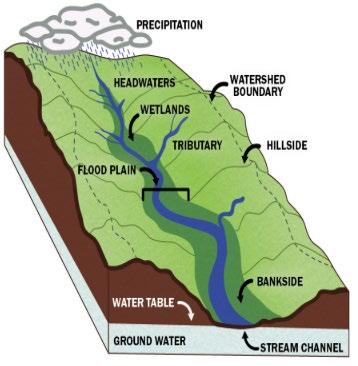
A watershed is an area of land where all the water from rain or snowmelt drains into a common body of water, such as a river, lake, or ocean. Water from precipitation travels in a watershed on the surface or underground, shaping the landscape as it flows and providing a water supply to support the entire area. Watershed encompasses everything within its geographic boundary—soil, terrain, water, air, plants, animals, and people— as an interconnected ecosystem.They play a vital role in distributing water across the landscape, filtering and storing it, and buffering against environmental challenges like fire, floods, and droughts.
like these allow for great impact on the land, we also know that providing educational technical guides for land stewards is imperative to restoring our watersheds; people doing this work on the land is what will make the biggest difference. While these groups have aggregated the information in this guide, these types of techniques have come from land based communities across the Southwest and other regions.
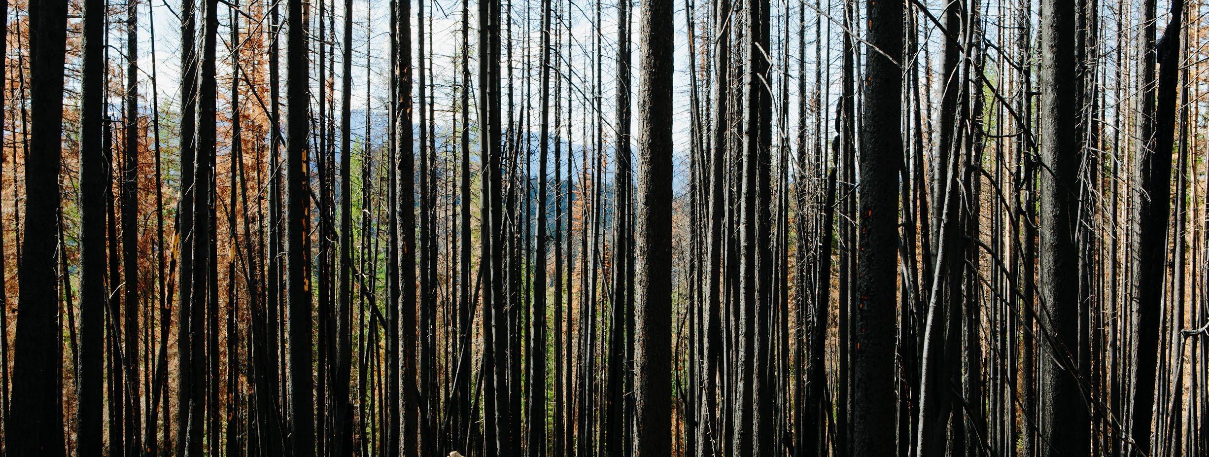
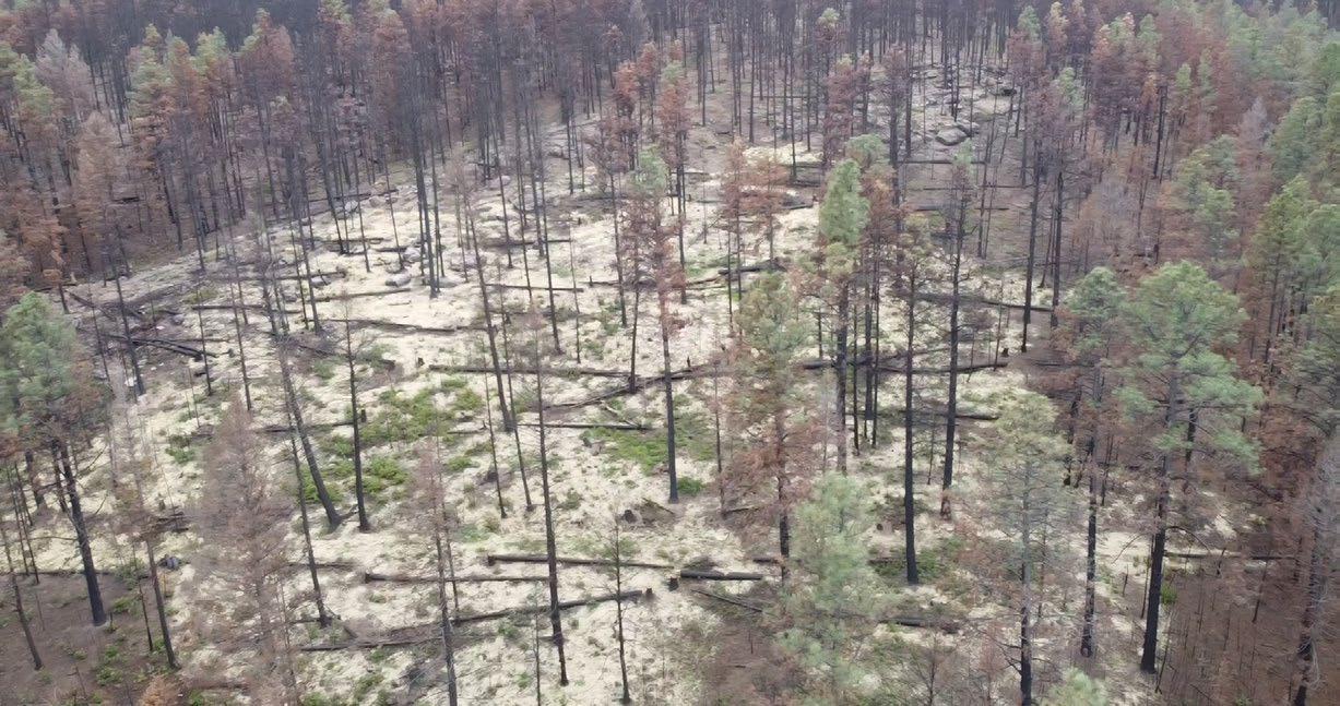
Watershed restoration is the process of repairing and enhancing natural processes and functions damaged by human activities, natural disasters (wildfire), or environmental changes, to improve health and resilience of land and water ecosystems. Wildfires can cause severe and lasting damage to a watershed, disrupting the natural functions and processes crucial to the ecosystem. Plants and trees that stabilize soil and slow water flow are destroyed, leaving the land bare and vulnerable to erosion. Scorching can cause soils to become hydrophobic (water-repellent), reducing water infiltration and increasing surface runoff. Runoff carries loose soil, ash, and debris into streams and rivers, causing sediment build-up and degraded water quality. In cases of increased precipitation, post-fire landscapes are susceptible to flash flooding.
Post-fire watershed restoration is best accomplished with low-tech, nature-based solutions that work with natural processes to repair damaged landscapes and restore ecosystem functions using local materials (rocks, logs, soil, and plants). Local materials mimic features found in nature and align with existing ecological processes, as opposed to synthetic materials (concrete, rebar, etc.) that can have negative long term impacts on the environment. Low-tech nature-based solutions require minimal equipment and can be hand-built in most cases. Over time, these solutions become a part of the natural landscape, making these solutions more sustainable and resilient compared to engineered alternatives.
Some post-fire watershed restoration goals include:
• Reduce surface water flow velocity, spread it across the landscape, and sink it into the soil to increase infiltration rates
• Prevent erosion and degradation in uplands, drainages, wetlands, and other critical areas.
• Protect features from degradation or excessive erosion
• Reconnect drainages to their floodplain
• Aggrade and restore deeply incised channels
• Reestablish flow in abandoned stream channels
• Temporarily store water on floodplains to raise the water table and increase groundwater recharge
• Promote capillary action to draw water upward and sustain vegetation
• Capture and distribute sediment and organic material
• Reduce damage caused by floods and increased water flow by slowing and spreading water
• Promote revegetation of native plants to stabilize soil
• Restore ecological processes that support watershed function
• Add structural complexity and biological diversity
Watershed restoration after fire is particularly critical to prevent or repair significant and long-term impacts to watershed health, water quality, and quantity. Rapid restoration work can save considerable money and effort in the long-run.
This guide is designed to guide restoration of small drainage channels, such as ephemeral or intermittent streams, which flow only during precipitation events, monsoon season, or spring snowmelt. These drainage channels include land features like arroyos and swales, which are vital components of watershed systems.
The guide provides step-by-step instructions for constructing low-tech nature-based restoration structures, explaining their purpose, how they function, and where to build them. It also includes design considerations, adaptations, for each structure. Structures in this guide can be built by hand using onsite or delivered materials, such as rocks and logs. Many of these structures can be built using heavy equipment if their scale is too large for hand work.
These foundational structures in this guide serve as reliable models, however structures should be customized to meet the specific needs of the landscape and water drainage conditions. Customizations may involve modifying the shape, size, or materials used to ensure the structures work effectively for the given situation. This guide emphasizes understanding how these structures function so that they can be thoughtfully adjusted or combined to address unique challenges.
Structures in this guide can be restorative, preventive, or designed to repair degradation, and in some cases perform multiple functions. Restorative structures are designed to reinstate natural functions or processes in the watershed. For example, a baffle may cause some erosion but is intended to restore meander patterns. In contrast, structures like Zuni Bowls are not restorative but are designed to arrest and address headcut erosion. Another example is a One Rock Dam designed to aggrade a channel. Structures like Zuni Bowls are not restorative but are intended to arrest and repair headcut erosion. Both types of structures can be implemented in a stream reach to address various forms of degradation.
While this guide focuses on structural techniques, it is important to recognize the role of other essential restoration practices, such as revegetation, which are covered in other resources. Together, these methods contribute to holistic watershed restoration and long-term ecological resilience.
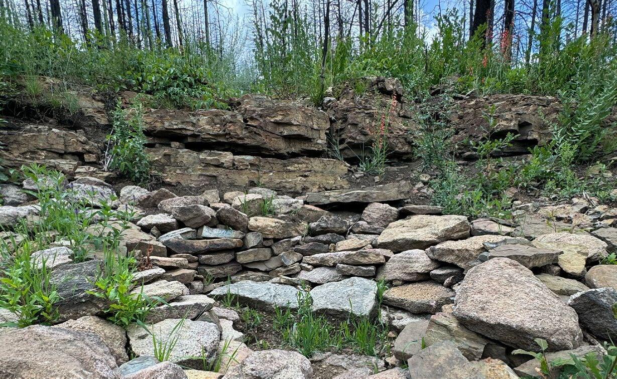
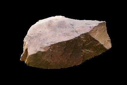
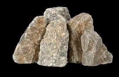
The following structures are constructed by gathering and arranging rocks of various shapes and sizes into interlocking patterns. Using rocks to build restoration structures has several benefits, one being they are plentiful in many remote settings making them readily accessible for projects.
Rocks are also naturally occurring on the landscape (unlike concrete or other man-made materials) and provide a long-term element that doesn’t need to be
SAFETY NOTE:
removed later. Using local rocks reduces the cost of restoration by lowering transportation costs and minimizing the environmental impact associated with moving materials with heavy equipment Larger rocks are typically used as anchors or support, while smaller rocks fill the gaps between larger ones (this process is called "chinking"). Rocks that have relatively flat surfaces are ideal for the foundation of certain structures, providing a solid base for stability and area to absorb the impact of falling water.

When working with rocks, the most common injuries are caused by accidents that occur while handling rocks. For example, a rock falling on your foot or crushing a finger between rocks. Always be aware of your body position and surroundings when moving rocks. Some rocks may be home to wildlife, such as snakes, lizards, or spiders, so avoid disturbing them or placing yourself or others at risk. When rolling large rocks downhill, always call out “rock” so any nearby crew members are aware and be sure no-one is present within the rolling zone.
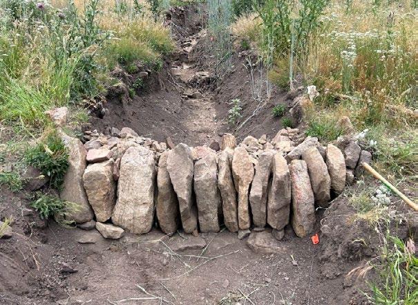
A one rock dam (ORD) is an in-channel grade control structure used for restorative purposes to slow water flow, reduce erosion, and manage sediment. Despite the name, an ORD is composed of multiple rows of rocks arranged in uniform height across the channel or streambed. These rocks interlock to form a barrier that slows water flow, captures sediment, and helps raise the streambed over time. The accumulation of sediment behind the structure raises the channel bed, and may
One rock dams are typically built in ephemeral stream channels experiencing downcutting (entrenchment) or incision. but they can also be applied in intermittent and perennial streams as well. ORDs are typically built in gullies less than 15 feet in width, where the structure can be more easily stabilized and water flow is concentrated.
help connect it to its floodplain (allowing floodwaters to spill out of the channel, dissipating energy and dropping out debris and sediment), and/or help to raise the water table. ORDs stabilize the channel and prevent channel erosion, especially downcutting, by slowing the flow of water, increasing roughness, and capturing sediment. Newly-collected sediment helps establish a seedbed and may collect plant propagation material.
STEP 1
Prepare the site by clearing the area of any loose rocks and debris, and leveling the surface where the structure will be built.
STEP 2
It is best to use natural features like large rocks, tree stumps, or the banks to anchor these structures. Areas with a gentle to moderate slope are preferred, as they allow the structure to control flow without being washed away during high flow events.
Dig a shallow trench (about 6 inches deep) at the downstream edge of the structure, perpendicular to the channel and spanning the entire channel width. Lay large, flat rocks interlocking in the trench so that no rock protrudes more than 2 inches above the bed of the channel. This first layer of rocks is called the footer or splash pad. This first row should extend up the side slopes to prevent water from going around the edge of the structure. The footer helps prevent undermining of the structure during high flows.
STEP 4
Arrange an additional four or more rows of interlocking rocks directly behind the first row (in the upstream direction). Rocks should be placed with their longest sides parallel to the flow of the channel, rather than perpendicular across it. These rows could be book-stacked depending on the thickness of the rock to maximize height per rock. As you approach the final (upstream) row, the rocks may gradually decrease in height.
STEP 5
Test the structure by walking across it. Notice any rocks that may move out of place and need to be adjusted or replaced.
STEP 3
Build the first row of rocks, overlapping 1/3 of the splash pad (footer) rocks across the channel. If necessary, arrange this row in a “book stacking” manner to reach a taller height, depending on rock dimensions
STEP 6 (optional)
Seed the structure with a locally-appropriate native seed mix and/or a sterile non-native cover crop.
STEP 7
Fill buckets with smaller, gravel-like rocks and empty them onto the structure to fill gaps. This process is known as chinking, and has proven to play a role in the stability and effectiveness of the structure. Avoid packing dirt between rocks as this excludes native seeds and organics, reducing growth of native vegetation.
In situations where rocks are scarce, hauling in additional rocks or using alternative materials like sandbags filled with local dirt or clay may be necessary. Sandbags may only last one year depending on the material they are made of, however their longevity can be increased by wrapping them with UV resistant material. An ORD-like structure can also be built with logs (see the log step down and log mat structures in the following pages).
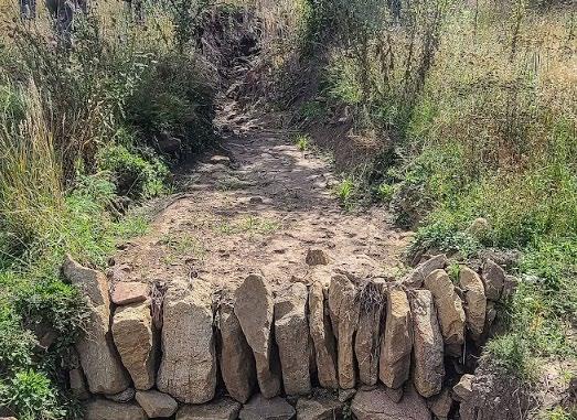
After several high-flow events, sediment should accumulate on top and upstream of the ORD. The goal is that the channel aggrades (builds-up) until flood flows are connected to the floodplain. In more entrenched channels, once the original layer has collected some sediment, another structure can be built starting at the third row of the existing structure. The original ORD becomes the splash pad for the new layer. With high-flow events, rocks may be dislodged from the ORD. In this case, it may be necessary to reposition them or replace them with larger rocks.
Rocks may decrease in size as the structure moves upstream, leveling out with the channel bed, however a One Rock Dam should be one rock in height throughout the entire structure. The splash pad should be large enough to prevent scour from water running over the structure and undermining it. The customary treatment is that all rows extend up the side slopes to prevent water from going around the edges of the structure, however occasional exceptions may be appropriate. ORDs should be placed in straight sections of the channel or the cross over. Many of them can be built in a sequence or paired with other structures (baffles).
The splash pad is a very important element of the ORD if the location site is scarce of subsurface rock. Especially in post-fire scenarios, it should be large enough to prevent scour from high flows running over the structure and missing the splash pad. Making it larger can be accomplished by selecting very large rocks if available or building splash pads with two layers – the first layer dug into the bed and the second layer on top with an alternating layout to prevent water from moving through the interstitial spaces.
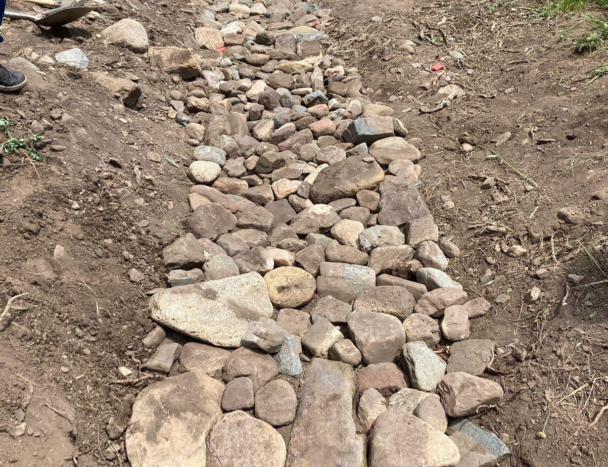
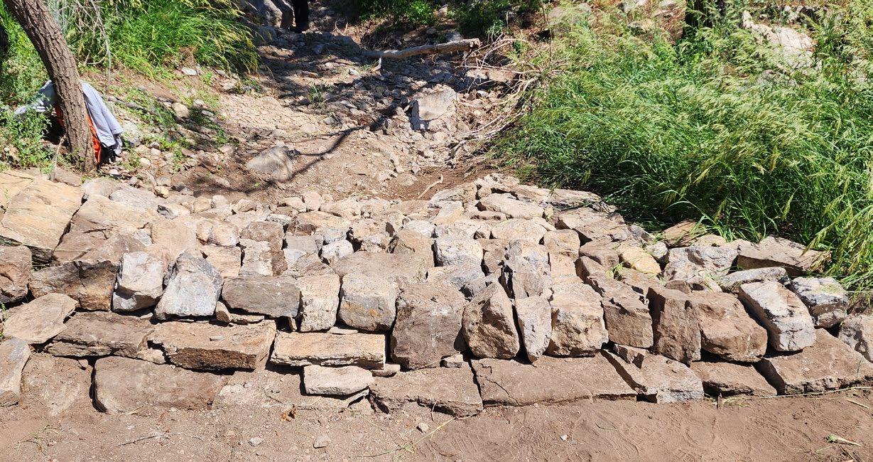
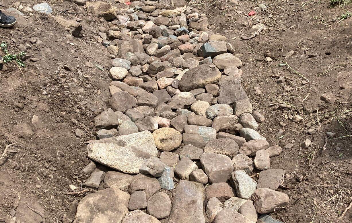
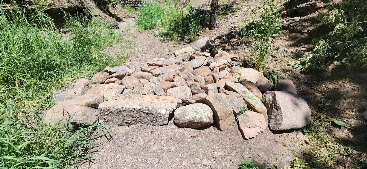
A rock rundown is a low-tech erosion control structure designed to stabilize low-energy headcuts in channels with a gentle to moderate slope and prevent further channel degradation. Rock rundowns reduce erosion by slowing surface water flow, dissipating erosive energy, and trapping sediment and moisture between rocks, which encourages plant growth. A rock rundown works by channeling water down a controlled path lined with rocks, which disrupts the flow of water , which helps to disperse the energy and prevent soil loss. As water flows over the rocks, it slows down, allowing sediment to settle behind the structure. This sediment accumulation helps stabilize the channel bed and establish a medium for plant growth. Over time, these structures contribute to the recovery of degraded channels, improve water infiltration, and support reestablishment of native vegetation.
Rock rundowns are typically used to prevent the formation of headcuts in upland areas and small, ephemeral streams. They are best suited for low-energy headcuts less than 2 feet in height; larger or more active headcuts may require a different structure (ex: Zuni Bowl). Rock rundowns work best when constructed on moderate to gentle slopes where water flow is not too fast.

STEP 1
Prepare the location by clearing the area of any loose rocks and debris, and leveling the surface where the structure will be built. Leave large, flat rocks in place and incorporate them into the structure.
STEP 2
Arrange large, flat rocks on the bed and banks of the channel, flipping and rotating them as needed to achieve an interlocking mosaic pattern. The rocks at the upstream/ uphill end should completely cover the headcut and adjacent bare or eroding surfaces. Continue placing rocks until the desired length is reached.
STEP 3
Fill any gaps between rocks by chinking with smaller rocks.
STEP 4 (optional)
Seed the structure with a locally-appropriate native seed mix and/or a sterile non-native cover crop.
STEP 5
Test the structure's integrity by walking across it. Notice any rocks that may move out of place and need to be adjusted or replaced.
Rock rundowns can be customized to suit various site conditions, even when rocks are scarce. They can be built using sandbags made of biodegradable material such as jute as a short-term solution. Alternatively, logs can be used in place of rocks to make a “log rundown” as long as it is anchored properly. As the structure interacts with surface water flow, rocks, logs, or sandbags may shift out of place and require replacements. Ensure the structure is anchored using large rocks on the edges of the channel.
Rocks used in rock rundowns should be heavy enough to withstand the force of flowing water and remain in place. A common misconception when building these structures is to “just throw rocks in the channel.” Rocks should be placed neatly and interlocked to create a structure capable of withstanding high-flow events.
Using rocks that are angular and various shapes is preferred over rounded river rocks, as their irregular shape allows for interlocking. The lip of the structure should not be higher than the surface surrounding the headcut, as that can redirect water around the structure, potentially causing erosion.
A media luna is a crescent-shape rock structure used in upland situations to prevent erosion and distribute sheet (surface) flow. The structure can be considered as a flow splitter as it redirects sheet flow by moving it away from a newly forming headcut or erosive area. It can also redirect dispersed flow into a defined channel or wetland to keep these areas wet. It can also be considered as a water harvesting structure which means it increases the residence time of surface flow, attenuating the volume and velocity of water that may travel to a headcut.
A media luna has two different purposes depending on how it is assembled. We refer to the two points at both ends of the structure as the tips of the structure when facing upslope. A media luna can have a convex or “tips up” design and it can have a concave or “tips down” design. In a tips up media luna, water enters the short side of the curve and exits through the long side, dispersing over a larger depositional area. A tips down media luna concentrates sheet flow uniformly over a smaller area, preventing developing gullies and rills from eroding upslope.
Flow paths on alluvial fans can become disrupted following the effects of a wildfire, making them an ideal location for these structures. A media luna is commonly used on alluvial fans that have been degraded due to incision and headcut migration. They can be built on slope wetlands, or gentle to moderate upland slopes that are experiencing erosive sheet flow. They need to be built on relatively
flat areas in order to channel water properly and are not applied in a stream channel. In locations with numerous rills, broadscale erosion can be reduced by collecting flow in one channel with a tips down media luna. A media luna can help concentrate dispersed flow across the entire available surface, promoting increased water storage and catchment of smaller sediment and debris.
STEP 1
Choose a relatively flat area with moderate sheet flow to build the structure and determine which variation (tips up or tips down) of the structure to build.
STEP 2
Prepare the site by gathering (staging) building materials and leveling the surface by removing loose rocks or debris. Outline the shape of the media luna in the ground using a shovel or digging bar.
STEP 3
Arrange the first row of the structure by placing large, flat rocks along the outline, with their widest part of the rock facing the same way. Larger rocks should be placed in deeper areas of the channel to achieve the requried height, while smaller rocks should be placed in more shallow areas to reach a uniform surface elevation across the structure.
STEP 4
Continue placing additional rows of rocks to extend the crescent shape until the desired size and shape of the structure is achieved, filling any gaps between rocks with chinking.
STEP 5 (optional)
Spread native seed or a sterile non-native cover crop over the structure.
STEP 6
Test the structure's integrity by walking across it. Notice any rocks that may move out of place and need to be adjusted or replaced.
A media luna can be modified by using sandbags, straw bales, or logs if rocks are scarce or absent at the site, however this affects the longevity of the structure. Sandbags are not expected to last more than one year, depending on the material they are made of. They should be made of natural materials (ex. jute) to reduce environmental
impact and should not be used in places where long-term protection is needed. Straw bales may have to be staked in place if large quantities of water flow are expected. If high flows displace any rocks, use larger rocks and secure them properly.
Rocks used in a media luna should be heavy and stable enough to resist displacement by water. They should be built on relatively flat ground to minimize the risk of further erosion. Both tips of the structure should be at the same elevation to ensure even water distribution and prevent from bypassing the structure. Uneven tips can
lead to unintended channelization or incision Multiple media lunas can be built across an alluvial fan or eroding area to prevent channel incision. Inspect the structure after heavy rainfall or seasonal changes for signs of erosion, displaced rocks, or structural weaknesses.
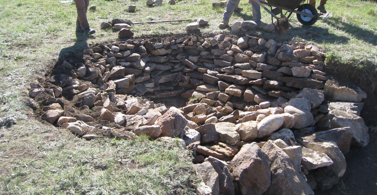
The Zuni bowl is an in-channel, headcut control structure that was developed by Bill Zeedyk, inspired by structures used by the people of the Zuni Pueblo in New Mexico. The Zuni bowl uses the principles of step-pools to create multiple drops that dissipate the energy of water falling from the pour-over of a headcut. By doing so, it stabilizes the headcut by replacing the original, actively eroding fall
with two or more subtle falls. The design of this structure also helps retain moisture in soil surrounding the bowl, promoting vegetation growth. This structure stops headcut migrations up valley rather than restoring channel functions. However, the created pools offer temporary habitat and water supply for plants and wildlife.
Ideal locations for Zuni bowls include areas with eroding headcuts in small to medium-sized channels experiencing headcut migration. They work well in semi-arid regions where controlling water flow is critical to maintaining landscape stability. Zuni bowls can be used in upland situations to treat headcuts under 4 feet in height and can be addressed by a hand-built Zuni bowl. Headcuts
greater than 4 feet in height may require assistance from heavy equipment and large rocks. Locations with accessible rock materials and existing features, such as partially formed pools, reduce construction effort and improve integration into the existing landscape, reducing the need for extensive modifications of the landscape.
STEP 1
Start by selecting an appropriate headcut to address. Shape and lay back the face and lip of the headcut to create a stable surface with sufficient space to accommodate the rocks used in construction of the structure. Level the base by removing loose material.
STEP 2
Gather and stage rocks of varying shapes and sizes, selecting many large, stackable rocks with flatter rather than rounded surfaces.
STEP 3
Line the base (at the downstream end) of the Zuni bowl with large, flatter rocks to create a splash pad for the structure.
STEP 4
Construct the first step of the bowl by placing a row of rocks overlapping about a third of the splash pad. These rocks should be positioned at approximately ½ of the total height of the headcut, if possible. This will form the lower pour-over of the bowl.
STEP 5
Construct the perimeter of the bowl by building the bottom row first and overlapping subsequent rows layered and sloping them into the bank. The top layer should be flush with the upstream channel bed. Add other layers of rock on the left and right banks so that the top layer is higher than the lip of the fall.
STEP 6
Line the bottom of the basin of the structure with rocks to create the plunge pool. Continue laying rocks up to the sides to the height of the bowl perimeter. Rocks should be greater than 6 inches in diameter and gaps should be filled in as much as possible. This forms the bowl.
STEP 7
Construct an ORD downstream from the Zuni bowl. Place the upstream edge of the ORD approximately six to eight times the height of the headcut away from the lower pour-over.
STEP 8
Seed the structure with a native grass mix and/or a sterile non-native cover crop.
While we described the typical shape of a Zuni bowl, the structure can be adapted to fit the unique contours of the landscape. Variation in shape may be necessary in areas that have uneven banks or natural obstructions. Use heavy, angular rocks to build the structure and interlock rocks together. Replace and secure rocks that dislodge
from the structure after high flows. In some cases, logs can be incorporated into the structure as a substitute for rocks or to provide additional stability. Check that the plunge pool is still intact and has not been overly scoured or filled with sediment.
The rocks must be arranged such that water falls off and onto rocks rather than the ground to prevent further erosion. Zuni bowls up to 3 feet in height can be built by hand using 10-50 lb. rocks. However, anything larger may require assistance from heavy equipment. Each layer of rock should lean slightly into the banks and be partially
supported by the rocks below it. Interlocking rocks together distributes the weight evenly and prevents slippage. An uneven lip can cause water to bypass the structure, leading to new erosion and reducing the effectiveness of the Zuni bowl.
A baffle is an in-channel structure designed to restore and protect stream channels. It is often used in a series to encourage the formation of meanders in unusually straightened channels. A baffle series promotes meandering by inducing bank erosion on one side of the channel, while accelerating sediment deposition on the opposite side. This process lengthens and flattens the channel, reducing its gradient, preventing downcutting, and promoting floodplain reconnection. A baffle is usually composed of large rocks arranged in a triangular design, then followed by a one rock dam. These two structures are then repeated downstream to create a series.
A baffle series creates dynamic stability and channel diversity. The new meander pattern has features associated with it like cut banks, pools, point bars, and riffles, all offering different substrates and unique habitat to support diverse plants and animals.
Adding or extending meanders means that water travels a longer distance over the same vertical drop, which slows the flow and reduces its erosive power. A baffle alone can also be used to deflect water flow away from eroding slopes that are jeopardizing important features.
Baffles are most effective in influencing sinuosity in small straightened streams where flow dynamics have been disrupted. Baffles work well in streams with gentle to moderate slopes where flow energy can be effectively
managed to prevent erosion and support sediment deposition. As with other structures, it is best to build a baffle in an area that incorporates natural structural elements, such as large boulders or tree stumps and roots.
STEP 1
Pick an appropriate site for construction.
STEP 2
Prepare the site by gathering (staging) building materials and leveling the surface of the channel by removing loose rocks or debris.
STEP 3
Arrange the first row of rocks at the downstream end of the structure and perpendicular to the bank, extending the row to ½ the channel width. This creates the base and tip of the baffle.
STEP 4
From the base tip of the baffle, move upstream, placing rocks in rows that become narrower the farther upstream you move until only one rock is placed at the apex of the triangle. The structure makes roughly a 60:30:90 degree triangle with the hypotenuse being about two times the length of the base.
STEP 5
Build a One Rock Dam downstream of the apex of the baffle.
STEP 6
Repeat the process above to construct another baffle on the opposite bank followed by another ORD structure downstream to induce a meander pattern. This can be repeated as far downstream as is desirable.
STEP 7
Fill any gaps between rocks by chinking both structures. Seed the structure with a native grass mix and/or cover crop.
STEP 8
Test the structure's integrity by walking across it. Notice any rocks that may move out of place and need to be adjusted or replaced.
In areas where rocks are absent, a baffle can be built using wooden posts staked securely into the ground following the same triangular design. Logs can also be incorporated into a rock baffle to increase stability, and to help maintain the triangular shape. These logs can be placed along the upstream or downstream edge, depending on flow dynamics and site conditions. Replace any washed-out rocks and secure them to the structure.
Though many shapes of baffles have been built, the most effective shape has proven to be a 60:30:90 degree triangle. Rocks used in baffle construction should resist expected flood forces, however, they should be uniformly sized so that the surface of the structure is streamlined. When incorporating logs into the structure, ensure they are anchored securely to prevent displacement. Logs can add roughness elements which can help capture sediment and provide habitat for wildlife. The placement of the baffle and one rock dam series should follow the natural flow path of the stream to maximize their effectiveness.
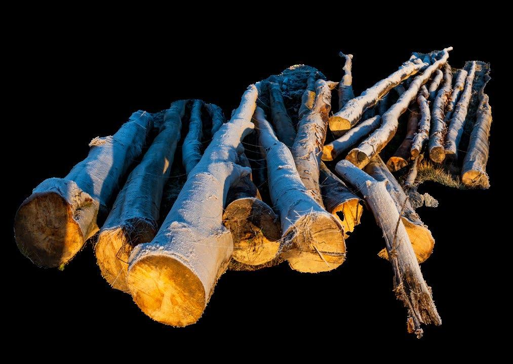
The following structures are created by gathering and arranging logs (and sometimes rocks) of various lengths and diameters to control erosion, sequester sediment, or reduce flow velocities in small channels. Like rocks, there are many benefits to using logs to build restoration structures. Logs are often abundant in most remote settings, especially after a wildfire, making them a practical and accessible resource. Utilizing dead or burned trees for restoration projects gives them a meaningful purpose, repurposing what would’ve gone to waste. Another advantage of using logs is their biodegradability; over time, they decompose and enrich the soil. Additionally, logs are naturally heavy and, when placed correctly, are unlikely to shift out of position.
Some structures will require tree felling, and in these cases, it is best to have an experienced sawyer to cut trees and logs. A sawyer is a trained individual on the crew that handles all the chainsaw work (felling, bucking, cutting, etc.). Always prioritize safety when working near a sawyer. A chainsaw is a powerful and useful tool, but has many hazards associated with its improper use and handling. Be mindful of your overhead and immediate surroundings, as vibrations from chainsaws—or even wind—can cause branches to break and fall unexpectedly. Pay attention to the sawyer's calls, such as "Falling!" or "Back cut!" and stay a safe distance out of the tree's fall path to avoid injury.
A log mat is a low-tech, natural erosion control structure designed to stabilize incised channels, trap sediment, and reduce water flow velocity. It is built by arranging a single layer of logs horizontally across the channel bed or along its edges. By lining the bed of incised channels, log mats create a physical barrier that slows water flow and encourages sediment deposition. Over time, the deposited sediment raises the channel bed, reducing the
Log mats are versatile and can be used in both upland and wetland environments. In uplands, they help stabilize ephemeral or intermittent channels that experience high sediment loads during storm events. In wetlands, they help reconnect water flow with surface slopes and floodplains. Log mats work best in successive cross-over
depth of incision and allowing water to spread across a broader area. Log mats can prevent headcuts from migrating upstream and help maintain the integrity of the landscape and reduce further degradation. They are particularly effective in capturing larger sediment sizes, such as gravel and cobbles, which are often mobilized during high-flow events.
STEP 1
Pick an appropriate site for construction considering cross-over segments of the channel.
STEP 2
Prepare the site by leveling the surface of the channel by removing rocks or debris.
STEP 3
Communicate with the sawyer to fall trees and cut them into logs of a similar length. Use stout logs (8-12” diameter and 6-8’ long) to build a structure that can withstand high flows. Delimb one side of the log that will be the bottom of the log while leaving the limbs on the top. Branches that stick up may catch more material. Leaving some branches on the bottom (6-12 inches) may help anchor the log mat into the ground if rocks are scarce, however ensuring good surface contact is paramount to avoid undercutting of the structure.


segments of an incised channel, just before a curve. This placement allows the structure to anchor securely into the channel banks, reducing the likelihood of displacement during high-flow events. Log mats are most effective in channels where flow velocities are moderate to low, reducing the risk of displacement.
STEP 4
STEP 5
Place logs in a single row across the channel, parallel to the direction of flow. You may need to rotate logs and cut off any sharp edges to make them fit snugly. Fill any gaps between logs by chinking with rocks, gravel, and/or branches.
Armor the sides, upstream, and downstream end of the structure with large rocks for additional support.
STEP 6
Test the structure's integrity by walking across it. Notice any logs that may move out of place and need to be adjusted or replaced.
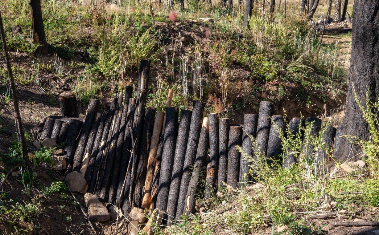
A log step-down is a restoration structure designed to stabilize deeply entrenched headcuts by filling them with stacked logs. This structure mimics the natural formation of step-falls or step-pools in streams (similar to a Zuni bowl), and is designed to break up a single, steep elevation drop into two or more smaller, manageable drops to reduce the energy of falling water. This slows erosion and prevents the headcut from migrating upstream, while promoting
sediment deposition. A log step-down can be used where constructing a Zuni bowl is not appropriate due to a lack of available materials. Log step-downs also serve as an effective solution for restoring hydrological connectivity. By stabilizing the headcut, they help maintain the integrity of slope wetlands and uplands, reducing the risk of further degradation.
Log step-downs can be applied in various settings where headcuts threaten the stability of a landscape. In uplands, log step-downs are effective at stabilizing ephemeral channels with moderate flow velocities or gullies where headcuts are forming, preventing further incision and erosion and reducing sediment transport downstream.
In slope wetlands, they help stabilize headcuts and maintain hydrological connectivity. Similar to Zuni bowls, log step-downs work best when treating headcuts that are 4 feet or less in vertical drop. For larger headcuts, additional logs or heavy equipment may be required to ensure the structure’s success.
Once the logs have captured enough sediment to raise the channel bed elevation, a second layer may be added to the structure. However, the second layer should be offset, upslope, and half the length of the initial log mat. Seeding the structure will help establish a new seed bed. Securing the structure with t-posts and wire is optional in
cases where rocks for armoring the structure are scarce. However, log mats have been proven at scale to function without external hardware allowing the costs to be reduced and alleviating the need to remove hardware once the duration of the structure's function has been reached.
It is important to get as much direct contact between the structure and the ground so water does not pass underneath the logs. Large, heavy logs should be used
for log mats because they are less likely to move, however this depends on the size of the drainage being treated and the anticipated hydrograph.
STEP 1
Pick an appropriate site for construction.
STEP 2
Gather and stage logs for the structure by felling trees and cutting them to the desired size. The logs should be cut into smaller and larger lengths to achieve a cascade effect.
STEP 3
Prepare the site by leveling the surface of the channel by removing rocks, debris, and other irregularities.
STEP 4
Place the first row of logs on the channel bottom at the base of the headcut. These logs should be the largest and longest.
STEP 5
Continue laying rows of logs up to the top of the headcut, decreasing in length of the logs as you reach the top.
STEP 6
Once you have filled the headcut with logs, you should armor the structure by placing large rocks on top of each row and also in any gaps.
STEP 7
Complete chinking with small rocks, gravel, branches, or sod on the structure to prevent undercutting.
Similar to the use of T-posts and wire, it is optional to use geotextile fabric between logs and the face of the headcut in successive layers to capture finer soil particles and retain moisture, however not necessary. Depending on the
quality and characteristics of the logs (e.g. burned vs. live, pine vs. fir), structures can function for 20 years or longer. Seeding the structure will promote plant growth around the sides and edges of the log step-down.
Log step-downs can be built by hand using three to four tiers of logs, and the logs should be about 8-12 inches in diameter. The logs at the bottom of the structures should be the longest and each tier should decrease in length to achieve a step-fall design. The logs in the top tier should
be slightly longer and should overlap the natural surface elevation above the edge of the headcut; this will make sure flood flows are focused toward the structure and do not go around it. Logs can be trimmed to length after the structure is built depending on the desired design.
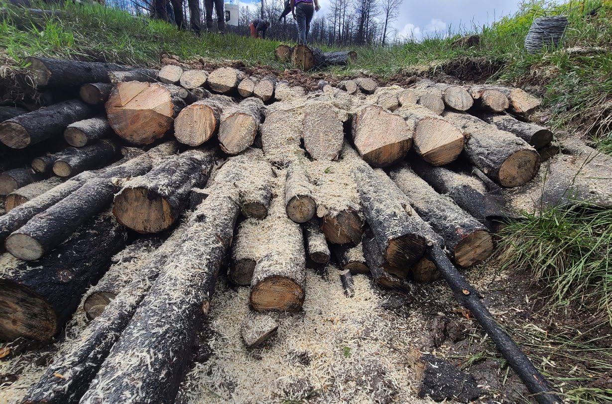
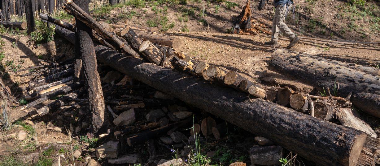
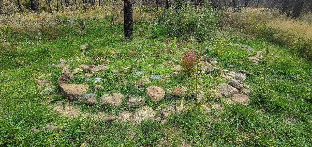
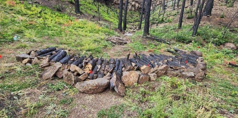
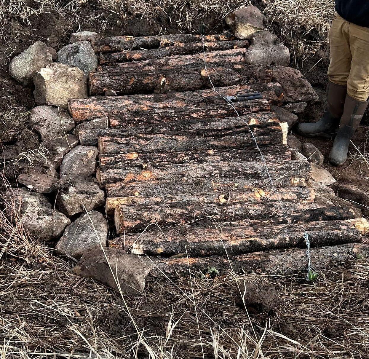
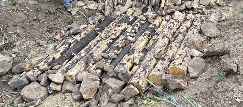
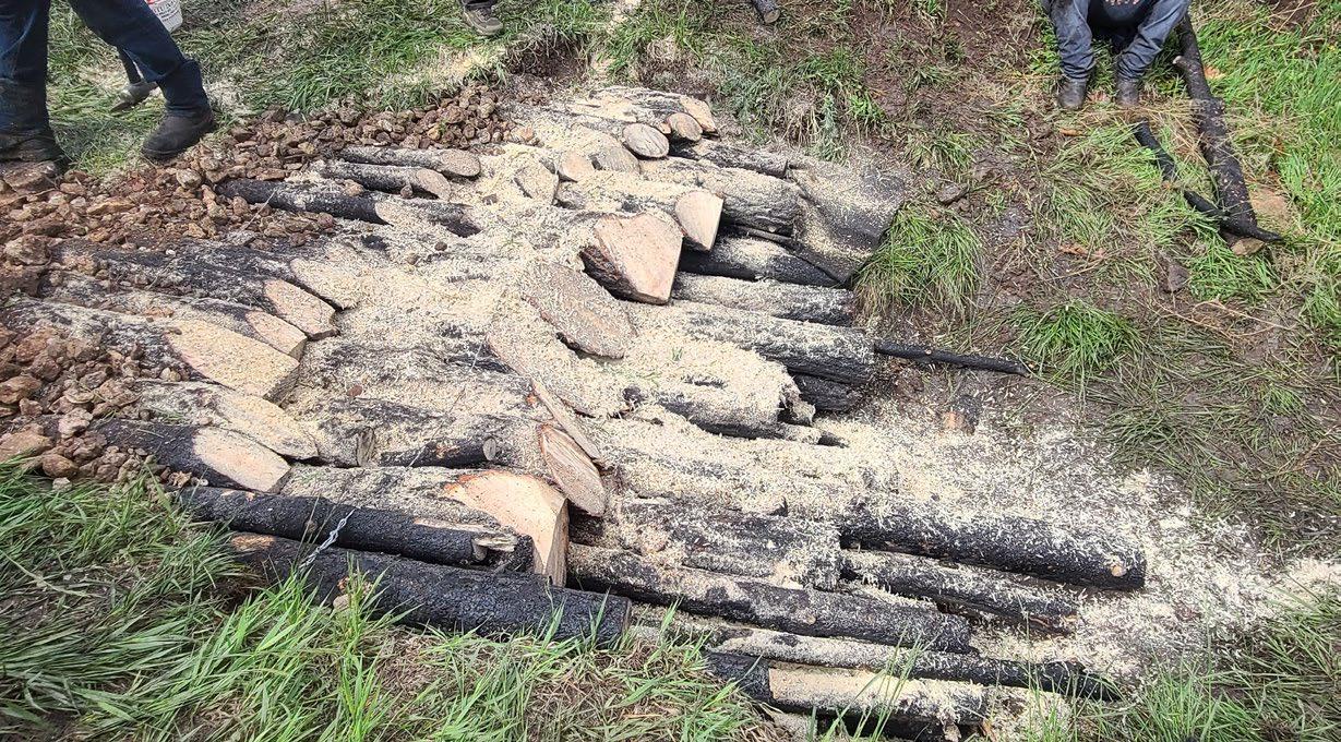
A trash rack is a multi-functional restoration structure designed to collect sediment and debris, control erosion, and mitigate flooding. It is constructed using a combination of logs and large rocks, arranged in a ramp-like or V shape. Trash racks are useful in post-fire landscapes, where erosion and sediment transport are significantly increased due to the loss of vegetation and soil stability. Unlike a dam, a trash rack does not block water flow entirely. Instead, water passes through at a slower rate, creating a more stable and controlled flow regime. This gradual reduction in flow helps protect downstream
areas from flash flooding while allowing sediment deposition upstream. Because water is allowed to pass over and through the structure, incorporating a step-down structure can help mitigate the elevation drop created by the trash rack. The collection of material and aggradation of the channel bed helps reverse effects from previous downcutting, reconnecting the channel to its floodplain. The biodegradable nature of logs and the use of on-site materials make trash racks an eco-friendly and sustainable choice for erosion control and watershed restoration.
STEP 1
Pick an appropriate site for construction.
STEP 2
High cut (leaving about a 2’ stump) a large tree (greater than 10” in diameter) directly across the channel; this will be the crossbeam of the rack. Move the felled tree upstream/uphill of the tree stump to hold the beam in place. Anchor the opposite side with either stumps or large boulders. If no trees are immediately adjacent to the desired site, the crossbeam can be placed in a shallow (1-2’ deep) trench dug perpendicular to the channel.
APPROPRIATE LOCATIONS
Trash racks can be used in various settings, particularly in small ephemeral channels or intermittent streams of post-fire and flood-prone landscapes. In these areas, trash racks mitigate the increased sediment and debris loads caused by burned vegetation and destabilized soils, reducing the risk of downstream flooding and sediment deposition. They can be built in ephemeral or small intermittent channels where downcutting or streambank
erosion is or has occurred. They are also helpful where the side slopes are contributing sediment, logs, debris, or rocks to the stream channel. Trash racks are suitable for channels where aggradation (raising the channel bed) is needed to reconnect the stream with its floodplain. This is particularly important in areas where past downcutting has disconnected surface flows from surrounding wetlands.
STEP 3
Gather and stage logs for the structure by felling additional trees and cutting them to the desired length. The logs should be long enough to rest on the bed of the channel and up to the crossbeam extending 1-2 feet above the crossbeam.
STEP 4
Make a ramp with the logs on the upstream side by arranging the cut logs next to each other with one end on the bed and the other resting on the crossbeam at an approximately 30 degree angle from the channel bed. Irregularities and branches that do not interfere with the placement can be left on some logs to help to entrain more debris and sediment. Rotate them as needed to minimize gaps between the logs at the bottom.
STEP 5
Fill any gaps between logs with smaller brush and branches. Armor the bottom of the ramp with large rocks if available.
STEP 6
Place a row of logs and or rocks behind the structure (downstream end) and underneath it to prevent the formation of scour pools and undermining; this row will act as a splash pad. Fill in any gaps both upstream and downstream with rock chinking or small branches. A log drop structure can be incorporated as well.
Once the structure has collected a significant amount of sediment, another trash rack may be constructed either upstream or downstream from the original. Seeding the structure before sediment collects will
help establish a seed bed. Seeding the collected sediment later will also help stabilize the sediment. Logs may wash away and need to be replaced with heavier logs or at a different angle.
Use a large log (10 inches in diameter or greater) for the crossbeam to add stability. The upright logs should also be large (8-12 inches in diameter) for strength. Upright logs should span the entire channel, closing the gap between the edge of the channel and the rest of the structure. Logs close to the channel edge will be shorter in length. Rocks used should be large enough to withstand displacement by water, except for the chinking.
When arranging the logs onto the crossbeam, keep them at an angle no more than 45 degrees but preferably 30 degrees. In heavily entrenched and actively eroding channels (like conditions found after fire), a series of trash racks (about 20-100 feet apart) can be very useful to sequester large quantities of sediment and reverse incision.
Trash Rack viewed from upstream (left) and downstream (right) in Sapello (Summer 2023).
Contour felling is a hillslope treatment designed to stabilize soils, reduce erosion, and promote recovery in steep, post-disturbance landscapes. This method involves placing downed logs in rows along the contour of the land, while ensuring direct contact with the ground. Contour lines can be better visualized on a topographic map, however the important part is the logs are placed in a line at the same elevation.
The logs act as barriers that slow water movement, trap sediment, and reduce surface runoff. Over time, contour felling promotes water infiltration, stabilizes loose soils, and creates a medium for vegetative growth. Contour-felled logs can be incorporated with other restoration methods such as worm ditches (conveyance swales), discussed in the following pages.
Contour felling is best suited for hillslopes in areas that have experienced moderate to severe burns, resulting in the loss of vegetative cover and leaving soils bare or hydrophobic. As mentioned above, contour felling must occur on the land’s contour. Contour felling is most
effective on slopes ranging between 20-60 percent, anything greater may require a different treatment. It is not as effective in rocky areas or uneven ground because it is hard to place logs in contact with the ground.
STEP 1
Locate a moderately- to severely-burned site to treat.
STEP 2
Determine the slope and identify the land’s contour, outlining the contour with flags. This will help determine the appropriate cross slope alignment of logs.
STEP 3
Fell appropriately-sized trees near the contour line, rolling them downslope if necessary. Leave the stumps about 12 feet high to brace the felled logs.
STEP 4
Remove tree limbs and set them aside to be used above or below the structure.
STEP 5
Place the log along the contour line and secure it so that it lies flat and maintains complete contact with the ground. Backfill with soil and slash to secure the log in place and prevent water from cutting under the log. As an alternative, place the log in a shallow trench long enough for the entire log or parts of it to be placed in. Cuts on the undersurface of the log can also be made to drop the log so it is in contact with the soil.
STEP 6
Use the slash set aside earlier to fill any gaps in the structure to help with sediment deposition.
STEP 7
Continue placing logs in a row following the contour line. As you move downslope, you may arrange the logs in a zigzag or terracing pattern to influence meandering between logs. Build subsequent rows on the slope to cover the area. Log rows can be spaced as far as 100 feet apart. Even one row of logs can be effective.
If successful, the structure will capture a significant amount of sediment, stabilize soil, and establish vegetative growth. If possible, seed the area uphill of the logs to encourage plant growth. Structures typically last one to two years and may require occasional maintenance, such as replacing displaced logs or re-chinking to maintain a tight seal. Functionally chinking the structure using soil, rocks, and slash can help stabilize the structure. Anchoring the log uphill and between two stumps or large boulders may help keep the structure in place.
Maintaining direct contact with the ground is very important when building this structure. Without full ground contact, water will flow under the log creating channelized flow and more erosion. It is highly recommended for a hand crew to work behind the sawyer, digging contour swales, packing brush, or laining the log with rock mulch.
Depending on the treatment site, contour felling can become costly and may require experienced labor. It is important to place the logs appropriately to ensure the structure works properly. Contour felling has been observed to significantly reduce erosion rates significantly, however placing logs inaccurately (2-5 degrees off contour) reduces sediment deposition drastically.
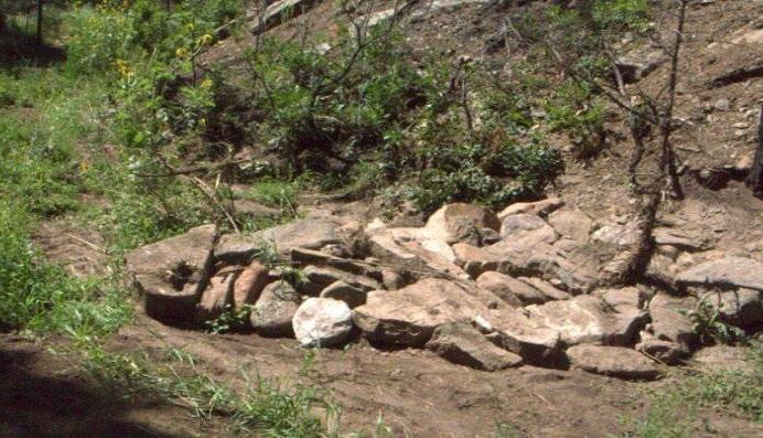
When finishing log structures, there is often material (extra logs, branches, slash, etc.) leftover, but not enough to build an entirely new structure. In these cases, wildlife slash piles may be constructed to provide shelter for wildlife
that has experienced loss of habitat post-fire and establish a medium for seed growth. These structures also protect the soil surface from erosion by providing ground cover on bare ground.
Wildlife slash piles can be built in a variety of settings, including open fields, rangelands, gullies, etc. Disturbed habitats where there is lack of habitat for wildlife are an ideal location for these piles. Areas that have an abundance of woody material are ideal for building
STEP 1
Step 1: Start by arranging the larger materials, such as logs, to form a base for the structure.
STEP 2
Place branches and slash around the structure, piling them onto each other.
STEP 3
Pile woody material until the desired height is reached.
STEP 4
Scatter seed inside and around the structure to promote vegetation.
these structures, however different materials can be used to build these piles. If successful, the structure will provide habitat as well as protection from predators and harsh weather conditions.
Any type of woody material can be used to build wildlife slash piles. These piles can also double as burn piles if at some point in the future it is desirable to do a controlled burn to reduce the risk of future fires.
Different designs of this structure can be made depending on the species you are building them for. If the opening at the bottom of the structure is too big, small prey may be unable to use the structures as protection from predators. A headquarters should normally be 4-6 feet in height when finished. The diameter of the structure should reach at least 15 feet.
A conveyance swale (sometimes referred to as a worm ditch) is a non-linear, shallow hand-dug trench used to transport water to rewet floodplains and wetlands that have been restricted from surface flow. It is also used
to spread water from eroding or downcutting channels across the surface of a wetland. This helps water reach areas where vegetation can utilize it and prevents flooding by providing different outlets.
AGGRADE
ALLUVIAL FAN
Worm ditches are built in areas where surface erosion is occurring and the channel bed cannot reach its floodplain. Digging a worm ditch from areas of confined flow can restore low-gradient sheetflow to dry areas. Worm ditches can also be used to divert water off of dirt roads by excavating to divert the water from the road onto the floodplain. Other purposes for worm ditches include diverting flow around a headcut or reconnecting the channel bed to the floodplain.
STEP 1
Step 1: Dig a trench in a meandering manner away from the channelized flow.
STEP 2
Armour the sides of the trench with rocks to stabilize the surface.
If the trench erodes or is filled with foreign or natural debris, you may have to repair the structure by digging the trench again and removing any debris. The structure can be used to divert water flow away from other structures, lessening the erosive force of the water. Other structures may be used in combination with a worm ditch to help with floodplain connectivity.
STEP 3
Periodically monitor the trench and remove debris that may have fallen in.
BOOK STACKING
To raise the level of a stream bed by the deposition of sediment.
A cone-shaped heap of alluvium (soil, clay, silt, or gravel) deposited by flowing water, as it slows down where the slope becomes gentle. An alluvial fan usually forms where steeply sloped streams reach the valley bottom and the slope becomes less severe.
A method of neatly stacking flat rocks on end next to each other, resulting in increased stability and structure strength.
CHANNEL The physical boundaries of water drainage systems, such as rivers, streams, or arroyos, consisting of a bed and banks.
CHINKING
Filling the space between logs or rocks in a structure with smaller rocks, dirt, or branches.
CROSS OVER The straight section of a stream between two meanders.
DOWNCUTTING
ENTRENCHED
When excavating the trench, try not to remove large rocks embedded in the soil, as this may cause erosion. Make the trench wide enough so that a considerable amount of water can move through the ditch, but beware not to make it too wide. The worm ditch should meander adjacent to the affected area, but may be used to help other structures function. The width of the ditch should be at least 2 feet with a depth of at least 1 foot. To divert flow around a headcut, the width and depth of the structure should be equal to the channel above the headcut.
EPHEMERAL STREAM
FLOODPLAIN
GEOTEXTILE
An erosion process that deepens a channel by removing material from its stream bed or a valley floor.
Describes a downcut channel that is disconnected from its floodplain during storm events, often characterized by vertical banks and narrow, deep channels.
A stream that flows only briefly during and after precipitation events and remains dry the rest of the time.
A flat or gently sloping area adjacent to a river, formed by sediment deposition during periods of high water or flooding.
A strong, permeable fabric used in construction and restoration to separate soil layers, provide infiltration, reinforce soil, and protect against erosion.
GRADE The surface level of the ground.
GRADE CONTROL
GULLY/ARROYO
HEADCUT
Techniques used to manage and stabilize the elevation and slope of the land or streambeds to reduce erosion and sediment transport.
A narrow channel or ravine, often caused by water erosion, typically found on slopes or in arid regions.
A steep vertical drop in a streambed or land surface, often formed by erosion processes. Headcuts tend to migrate upstream/uphill and cause further degradation
INTERMITTENT STREAM A stream that flows with water seasonally (ex: during spring snow melt, during or after monsoons), and remains dry for part of the year.
MITIGATION Actions taken to reduce or minimize adverse impacts (ex: erosion, flooding).
PERENNIAL STREAM A stream with continuous flow throughout the year, sustained by groundwater and consistent precipitation.
POINT BAR A depositional feature on the inner bend of a meandering stream, typically composed of sand, gravel, or sediment.
POUR OVER The section of a structure where water flows over the edge, designed to dissipate energy and control flow.
RESTORATION
The process of returning degraded landscape, habitat, or water body back to a healthier, more functional state.
RILLS Small, shallow, channels formed on the ground surface by running water, often the precursor to more significant erosional features like gullies.
SANDBAG A sturdy bag filled with local dirt, generally used as a substitution for rocks. They should be made of natural materials (ex. jute) and not used in places where long-term protection is needed.
SAWYER A trained individual on the crew that handles all the chainsaw work (felling, bucking, cutting, etc.).
SEDIMENT Particles of soil, sand, and organic matter transported by water, often deposited in riverbeds and floodplains.
SINUOUS
SPLASH PAD
UNDERMINING
WATERSHED
Having a winding or curving path, often used to describe meandering streams.
A protective surface, such as rocks or logs, placed downstream of a structure to absorb energy of falling water and prevent erosion and scouring.
The process of eroding the base or foundation of a structure, causing it to weaken or collapse.
A watershed is an area of land where all the water from rain or snowmelt drains into a common body of water, such as a river, lake, or ocean. Water from precipitation travels in a watershed on the surface or underground, shaping the landscape as it flows and providing a water supply to support the entire area. Watershed encompasses everything within its geographic boundary—soil, terrain, water, air, plants, animals, and people— as an interconnected ecosystem. They play a vital role in distributing water across the landscape, filtering and storing it, and buffering against environmental challenges like fire, floods, and droughts.
Let the Water do the Work: Induced Meandering, an Evolving Method for Restoring Incised Channels, Bill Zeedyk, Van Clothier (Eds.). Quivira Coalition, Santa Fe, NM, USA (2009)
Characterization and Restoration of Slope Wetlands in New Mexico: A Guide for Understanding Slope Wetlands, Causes of Degradation and Treatment Options, 2014
AUTHORS AND EDITORS:
Bill Zeedyk
Estevan Gonzales, Hermit’s Peak Watershed Alliance
Lea Knutson, Hermit’s Peak Watershed Alliance
Kristina Fisher, Albuquerque Wildlife Federation
Cameron Weber, Rio Grande Return and Albuquerque Wildlife Federation
Reid Whittlesey, Rio Grande Return
Anica Wong, Quivira Coalition


This guide is supported by a series of post-fire restoration videos being developed by Hermit’s Peak Watershed Alliance. The first is an introduction to watershed impacts from severe fire with a subsequent video that shows construction of structures in this guide They can be found on the Hermit’s Peak Watershed Alliance website at hermitspeakwatersheds.org under the Learning Together tab. Quivira Coalition also has numerous helpful and related resources on their website.
hermitspeakwatersheds.org quiviracoalition.org
abqwildlifefederation.org riograndereturn.org