7 minute read
Decarbonisation: GEA

GEA’s solution approach to the net-zero strategy
The re-orientation towards more sustainability and awareness of CO2emissions will have a significant impact on the design of e haust gas cleaning reports Dr. Marcel Zillgitt*.
Since it is clear that only a drastic reduction of greenhouse gas emissions can stop global warming, the industry is facing an unprecedented challenge.[1,2] For the glass industry as an emitter of CO2 various approaches to emission reduction are available, which require a reconsideration of the exhaust gas purification section. Due to increased certificate costs [3] as well as national and international pressure to energy savings and emission reduction, the attention for this topic is as high as rarely before. GEA as a partner for emission control systems offers solutions for the long-term and sustainable orientation of a prospective exhaust gas cleaning, heat recovery and a broad range of applications to use CO2.
Adaption to fuel switch
To reduce CO2 emissions, of which 75% are attributable to fuel consumption in the glass manufacturing process,[4] natural gas was used instead of oil for firing. This cost-intensive conversion has an effect on the composition of the process gas but is not sufficient to significantly reduce CO2 emissions. A much-discussed approach is to substitute the fuel with hydrogen if produced climate-neutral. Renewable energies such as wind, biomass or solar energy can therefore be used. With the change of these new input conditions in the combustion process, a conversion of the existing glass plant becomes a prerequisite. This also affects flue gas treatment and purification, which must be considered as a mandatory part of the plant. Special precautions must be taken here with regard to the changed Wobbe index and thus the burner selection, as well as the risk of corrosion due to high flame temperatures. Also, the high proportion of H2O in the flue gas can lead to enormous condensation quantities. This is particularly the case if cooling is necessary for subsequent process steps such as a carbon capturing.
In case of oxyfuel use for compensation of combustion air and thus nitrogen reduction, there is also considerable impact on the exhaust gas treatment. On the one hand, the reduction of the total volume flow means that plant sizes have to be reduced, for instance the
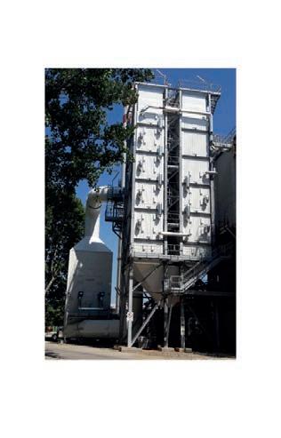
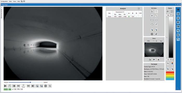
Fig 1. GEA’s vertical heat exchanger together with a SCR in a glass plant in Italy.
filter surface load. On the other hand, the relative proportion of impurities in the flue gas increases. In addition to the higher CO2 content, an uplift for the acid dew point temperature is to be expected. [5] GEA is aware of this problem and offers special material combinations, for example to operate heat exchangers in the critical temperature range.
Energy efficiency
The exhaust gas volume together with the available temperature level offer great potential for utilising thermal energy for various purposes. One example is the application of waste heat integration, which GEA Emission Control provides in its portfolio.
Here, the gas flow is passed through heat exchangers where a heat transfer medium such as water or thermal oil is heated. In principle, heat exchangers can be positioned in the raw gas and/or the clean gas, depending on available thermal power from the furnace and the gas temperature, taking into consideration the needs of the emission control system e.g. for efficient desulfurization reaction. Through special design of the raw gas heat exchangers such as suitable tube pitches high dust loads can be handled without problems in continuous operation. Fig 1 shows an SCR system and a clean gas heat exchanger in vertical gas flow direction.
Options for usage of the recovered heat include the provision of hot water or steam, drying of biomass such as sewage sludge, conversion to electricity or the generation of compressed air. In most cases the available heat is used to generate electricity with the help of an Organic Rankine Cycle (ORC). The transferred heat from the flue gas evaporates an organic medium, followed by the expansion of the organic steam in a turbine which is directly coupled to a generator. The physical properties of the organic media used enable flexible operation that can also compensate very well deviations in the amount of heat provided, e.g. due to different glass production campaigns or pull rates. As well due to the properties
Fig 3. Container-sized mobile CO2 separation unit.
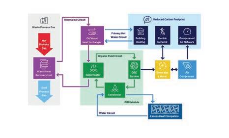
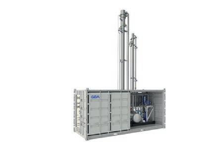
Fig 2. Utilisation of waste heat.
of organic medium the expansion takes place without critical droplet formation, which is why a long running time of the turbine blades is experienced.
Condensation is achieved by recooling, with flexibility for the use of air-cooled condensers (ACC) or water cooling, based on boundary conditions at the respective plant such as available space or availability of water. Fig 2 shows the basic possibilities of waste heat utilisation for different applications as well as the schematic of the ORC cycle for electricity generation.
By increasing the plant efficiency, energy can be converted in a meaningful way, so that the CO2 footprint and OPEX are reduced in the long term. For the future requirements on CO2 savings, which call for early action in view of rising certificate costs, the direct capture of CO2 from the waste gas stream must also be taken into account.
CO2 separation
Chemical absorption by means of amine solution is recognised as a commercially proven tail-end solution for post-combustion carbon dioxide separation.[6, 7]
The technology comprises of several steps: after pre-conditioning of the gas stream by cooling and separation of impurities, the prerequisites for lowmaintenance CO2 separation are fulfilled. The gas then enters an absorber column where it is contacted with a lean amine solution, which is introduced at the top of the column in countercurrent flow.
While passing the column the CO2 is absorbed into the liquid phase. From the sump of the absorber, the rich amine solution is transferred through a heat exchanger to a desorber column. Here, CO2 is released at high temperature by adding thermal energy and then further treated to the desired degree of purity.
The lean amine solution is then conveyed back to the absorber column. A certain proportion of the required heat to regenerate the solvent can be obtained, for example, from the energy recovery of the high temperature processes in the glass industry.
Although direct CO2 capture from the flue gas stream with amine scrubbing is state of the art, widespread application in the glass industry has not yet been implemented. However, the significantly increased costs for fossil fuels and the rising prices for CO2 certificates as well as the new awareness for sustainability could cause a re-evaluation of the use of this technology here. In particular, it is advantageous to specifically separate both process-related and energy-related CO2emissions, regardless of the fuel used.
GEA, as an expert for the entire exhaust gas cleaning line, adapts to this transformation and thus is currently starting up a pilot plant for investigation of specific operation conditions in the glass industry. Fig 3 shows the structure of the modular container of the CO2 pilot plant.
With a capacity of 150 to 200 Nm3/h, up to 500 kg CO2 per day can be captured with GEAs mobile CO2 separation pilot, depending on the feed gas composition. For test operation, campaigns of three to six months should be targeted to demonstrate the functionality, evaluate the stability of the chemistry and to eliminate concerns related to gas contamination. In the near future, plant sizes covering entire glass plants will be engineered for capturing > 90 % of the total CO2 emissions.
This is an essential step towards more sustainability and avoidance of greenhouse gas emissions in the glass industry. For this purpose, GEA offers adequate product solutions with regard to industrial exhaust gas purification to meet an efficient net zero strategy. Continuing the CO2 pathway, this also applies to liquefaction for transportation, conversion to carbonates or other chemicals as well as tailored CO2 utilisation support.
With these reliable and target-oriented approaches, we are focusing on the new importance of waste gas purification in conjunction with its interrelated challenges.
With these reliable approaches and in alignment with sustainability targets of our customers we are focusing on the new importance but also challenges related to waste gas cleaning, heat recovery and CO2 utilisation in glass industry.
References
[1] McKinsey Sustainability, https:// www.mckinsey.com/business-functions/ sustainability/our-insights/how-theeuropean-union-could-achieve-net-zeroemissions-at-net-zero-cost, last accessed on 25 July 2022 [2] E. I. Koytsoumpa; C. Bergins; E. Kakaras, The Journal of Supercritical Fluids, 132, 2018, 3-16. [3] EU Emission Trading System (EU ETS) - Revision for phase 4 (2021-2030), https://ec.europa.eu/clima/eu-action/ eu-emissions-trading-system-eu-ets/ revision-phase-4-2021-2030_en, last accessed on 25 July 2022 [4] Flat glass in climate-neutral Europe, https://glassforeurope.com/wp-content/ uploads/2020/01/flat-glass-climateneutral-europe.pdf, last accessed on 26 July 2022 5 Kather A., Kownatzki, International Journal of Greenhouse Gas Control, 5, 1, 2011, 204-209 [6] P. Loria; M. Bright, The Electricity Journal, 34, 2021, 106998 [7] International Energy Agency - CCUS technology innovation, https://www. iea.org/reports/ccus-in-clean-energytransitions/ccus-technology-innovation, last accessed on 27 July 2022
*Process engineer, GEA Bischoff, Essen, Germany www.gea.com