Product: COMPACT WHEEL LOADER
Model: 910M COMPACT WHEEL LOADER H22
Configuration: 910M Compact Wheel Loader H2200001-UP (MACHINE) POWERED BY C4.4 Engine
Disassembly and Assembly
910M, 914M, 918M, 910K, and 914K Compact Wheel Loaders, Engine Supplement Media
i06721643
Air Cleaner - Remove and Install
SMCS - 1051-010
Removal Procedure
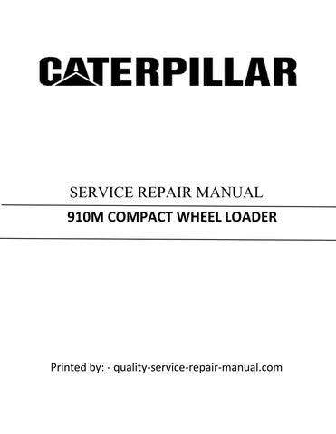
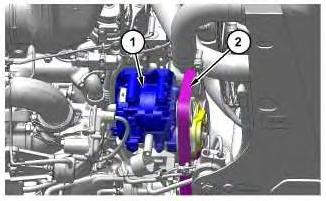
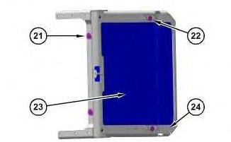
Illustration 1
g06091206
1. Disconnect harness assembly (1) from the temperature sensor and the air cleaner pressure switch (Not Shown) and remove the cable straps connecting harness assembly (1) to the air cleaner.
2. Remove bracket (2) from the air cleaner and set to the side.
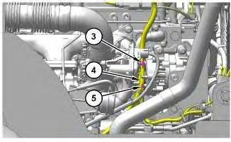
3. Disconnect intake tube (3) from the air cleaner.
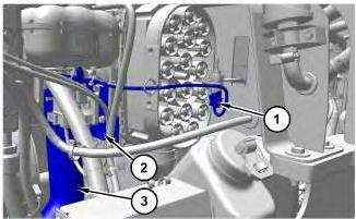
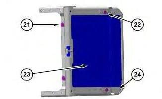
Illustration 2
g06091252
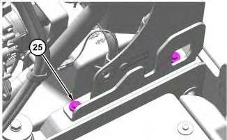
4. Remove bolts and washers (5) located behind air cleaner (4). Remove air cleaner (4).
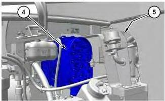
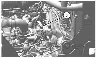
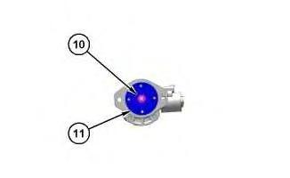
Illustration 3
5. If necessary, remove pressure switch (6).
g06091347
Installation Procedure
1. Install air cleaner (4) in the reverse order of removal.
a. If necessary, tighten pressure switch (6) to a torque of 2.25 ± 0.25 N·m (20 ± 2.0 lb in).
b. Tighten bolts (5) to a torque of 13 ± 3 N·m (115 ± 27 lb in).
c. Tighten clamp for air intake tube (3) to a torque of 5 ± 0.5 N·m (44 ± 4.0 lb in).
Copyright 1993 - 2021 Caterpillar Inc. All Rights Reserved. Private Network For SIS Licensees.
Wed Apr 14 15:42:13 UTC+0530 2021
Product: COMPACT WHEEL LOADER
Model: 910M COMPACT WHEEL LOADER H22
Configuration: 910M Compact Wheel Loader H2200001-UP (MACHINE) POWERED BY C4.4 Engine
Disassembly and Assembly
910M, 914M, 918M, 910K, and 914K Compact Wheel Loaders, Engine Supplement
i06702302
Alternator - Remove and Install
SMCS - 1405-010
Removal Procedure
1. Open left hood
2. Turn battery disconnect switch to the off position.
Illustration 1
3. Remove belt (2) from alternator (1). Refer to Operation and Maintenance Manual, "BeltsInspect/Adjust/Replace" for the correct procedure.
Note: Graphic is for reference only.
g06082532
Illustration 2
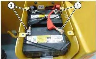
4. Remove nut (3) and (5). Position harness assembly (4) to the side.
Illustration 3
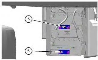
5. Remove four bolts (6) and alternator (1).
g06082694
Note: Graphic is for reference only.
Install Procedure
1. Install alternator (1) in reverse order of removal.
Copyright 1993 - 2021 Caterpillar Inc. All Rights Reserved.
Network For SIS Licensees. Wed Apr 14 15:28:39 UTC+0530 2021
g06082674
This is the sample of the manual click on the download link for complete manual
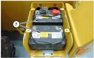
Install Procedure
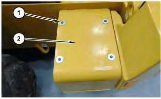
1. Install batteries (7) in reverse order of removal.
a. Tighten bolts (1) to a torque of 20 to 25 N·m (177 to 221 lb in).
Copyright 1993 - 2021 Caterpillar Inc. All Rights Reserved. Private Network For SIS Licensees.
Wed Apr 14 15:27:52 UTC+0530 2021
Product: COMPACT WHEEL LOADER
Model: 910M COMPACT WHEEL LOADER H22
Configuration: 910M Compact Wheel Loader H2200001-UP (MACHINE) POWERED BY C4.4 Engine
Disassembly and Assembly
910M, 914M, 918M, 910K, and 914K Compact Wheel Loaders, Engine Supplement
Breather (Crankcase) - Remove and Install
SMCS - 1317-010
Removal Procedure
1. Open the right rear engine enclosure door.
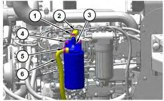
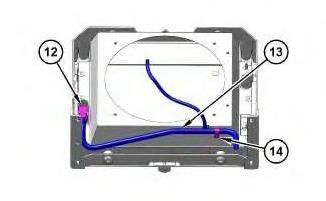
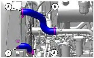
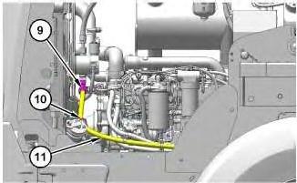
Illustration 1
2. Loosen clamps (1) and (5).
g06118566
3. Disconnect hose assemblies (2) and (6). Position hose assemblies (2) and (6) to the side.
4. Remove bolts (4) and breather (3).
Installation Procedure
1. Install breather (3) in the reverse order of removal.
i06792153
Copyright 1993 - 2021 Caterpillar Inc.
Rights Reserved.
Network For SIS Licensees. Wed Apr 14 15:35:00 UTC+0530 2021
Product: COMPACT WHEEL LOADER
Model: 910M COMPACT WHEEL LOADER H22
Configuration: 910M Compact Wheel Loader H2200001-UP (MACHINE) POWERED BY C4.4 Engine
Disassembly and Assembly
910M, 914M, 918M, 910K, and 914K Compact Wheel Loaders, Engine Supplement
Catalyst (SCR) - Remove and Install
SMCS - 1091-010
S/N - H221-UP
S/N - H241-UP
S/N - H261-UP
Removal Procedure
1
Hot engine components can cause injury from burns. Before performing maintenance on the engine, allow the engine and the components to cool.
1. Remove Left and Right hoods.
2. Remove Exhaust Flex Pipe.
i06736269
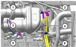
1
3. Remove cable strap (3) and disconnect harness connector (5). Remove temperature sensor (1).
4. Remove clamp (6). Disconnect and set to the side diesel exhaust fluid lines (2) and harness connectors (4).
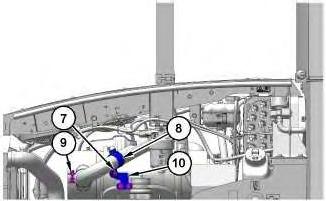
Illustration 2
5. Disconnect clamp (9). Remove three bolts and washers (7). Remove clamp (8) and bracket (10).
Illustration
g06094141
g06090065
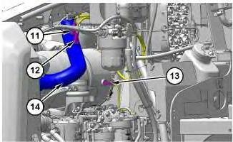
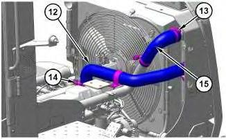
Illustration 3 g06090083
6. Disconnect and remove ammonia sensor (11) and nitrogen oxide sensor ( exhaust pipe out ) (12). Position sensors (11) and (12) to the side.
7. Remove temperature sensor (13). Remove tube assembly (14).
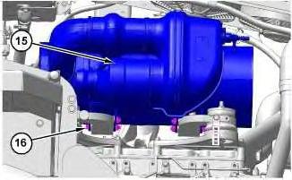
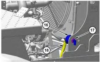
Illustration 4
g06090150
8. Remove four bolts (16) and Catalyst (SCR) (15).
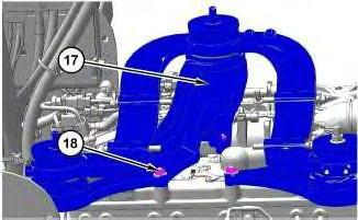
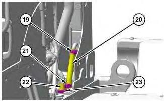
Illustration 5
g06090163
9. If necessary, remove seven nuts (18) and mount assembly (17).
Install Procedure
1. Install catalyst ( SCR ) (15) in reverse order of removal.
a. Apply tooling (A) to the threads of temperature sensor (1) and temperature sensor (13).
b. Apply tooling (A) to the threads of ammonia sensor (11) and nitrogen oxide sensor (12).
c. Tighten temperature sensor (1) and (13) to a torque of 45 ± 5 N·m (33 ± 4 lb ft).
d. Tighten ammonia sensor (11) and nitrogen oxide sensor ( exhaust pipe out ) (12) to a torque of 50 ± 10 N·m (37 ± 7 lb ft).
Copyright 1993 - 2021 Caterpillar Inc. All Rights Reserved. Private Network For SIS Licensees.
Wed Apr 14 15:32:19 UTC+0530 2021
Product: COMPACT WHEEL LOADER
Model: 910M COMPACT WHEEL LOADER H22
Configuration: 910M Compact Wheel Loader H2200001-UP (MACHINE) POWERED BY C4.4 Engine
Disassembly and Assembly
910M, 914M, 918M, 910K, and 914K Compact Wheel Loaders, Engine Supplement
Cooling System Package - Disassemble and Assemble
SMCS - 1063-017; 1353-017; 1805-017
Disassembly Procedure
Start By:
a. Remove Cooling Package.
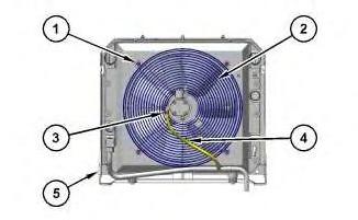
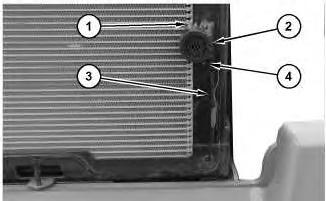
Illustration 1
i06688355
g06078024
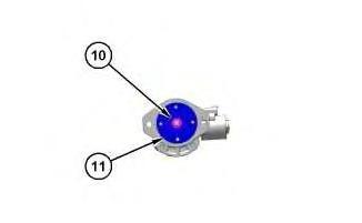
1. Position cooling package (5) on to suitable cribbing. Remove clamp (3) and position hose (4) to the side. Remove bolts (1) and fan motor assembly (2) from cooling package (5).
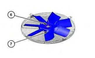
Illustration 2
2. Position fan and motor assembly on to suitable cribbing. Remove bolts (6) and fan (7).
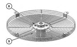
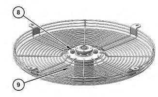
Illustration 3
3. Remove bolts (8) and fan guard (9).
g06071833
Illustration 4
4. Remove nut (10) and adaptor (11).
g06071818
g06071725
Note: If necessary, use suitable puller to remove adaptor (11).
Illustration 5
g06078228
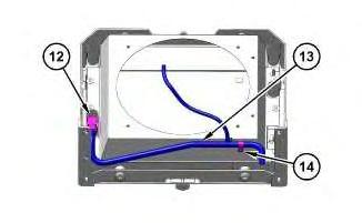
5. Disconnect fitting (12) and remove bolt (14). Remove tube assembly (13).
Illustration 6
g06078230
6. Remove six bolts (15) and fan shroud (16).
Illustration 7
g06078374
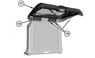
7. Disconnect strut assemblies (18). Remove bolts (19) and rear door (17).
Illustration 8
g06078238
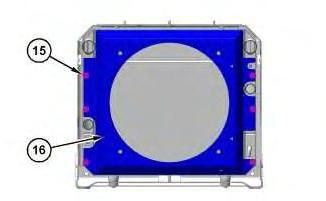
8. Position cooler frame (24) on its side on to suitable cribbing. Remove two bolts (21) and two bolts (22). Remove radiator (23).
Assembly Procedure
Illustration 9
g06078238
1. Position cooler frame (24) on its side on to suitable cribbing. Install radiator (23). Install two bolts (21). Tighten bolts (21) to a torque of 50 ± 10 N·m (37 ± 7 lb ft). Install two bolts (22). Tighten bolts (22) to a torque of 30 ± 7 N·m (266 ± 62 lb in)
Note: Check seals between radiator (23) and cooler frame (24).
10
2. Position rear door (17) and install bolts (19). Tighten bolts (19) to a torque of 15 ± 3 N·m (133 ± 27 lb in). Connect strut assemblies (18).
Illustration 11
3. Install fan shroud (16) and six bolts (15).
Illustration 12
Illustration
g06078374
g06078230
g06078228
4. Position tube assembly (13). Connect fitting (12) and install bolt (14).
Illustration 13
5. Install adaptor (11) and nut (10). Tighten nut (10) to a torque of 40 N·m (30 lb ft).
Illustration 14
6. Install fan guard (9) and bolts (8).
g06071818
g06071833
Illustration 15 g06071725
7. Install fan (7) and four bolts (6).
Illustration 16
g06078024
8. Position fan and motor assembly on to cooling package (5). Install four bolts (1). Connect hose (4) to fan motor and install clamp (3).
End By:
a. Install Cooling Package
Copyright 1993 - 2021 Caterpillar Inc. All Rights Reserved. Private Network For SIS Licensees. Wed Apr 14 15:40:51 UTC+0530 2021
Product: COMPACT WHEEL LOADER
Model: 910M COMPACT WHEEL LOADER H22
Configuration: 910M Compact Wheel Loader H2200001-UP (MACHINE) POWERED BY C4.4 Engine
Disassembly and Assembly
910M, 914M, 918M, 910K, and 914K Compact Wheel Loaders, Engine Supplement
Cooling System Package - Remove and Install
SMCS - 1063-010; 1353-010; 1374-010; 1712-010
Removal Procedure
Table 1
Required Tools
Tool Part Number Part Description Qty
A 439-3938 Link Bracket 2
Start By:
a. Remove Hood.
At operating temperature, the engine coolant is hot and under pressure.
Steam can cause personal injury.
Check the coolant level only after the engine has been stopped and the fill cap is cool enough to touch with your bare hand.
Remove the fill cap slowly to relieve pressure.
Cooling system conditioner contains alkali. Avoid contact with the skin and eyes to prevent personal injury.
i06791224
NOTICE
Care must be taken to ensure that fluids are contained during performance of inspection, maintenance, testing, adjusting, and repair of the product. Be prepared to collect the fluid with suitable containers before opening any compartment or disassembling any component containing fluids.
Refer to Special Publication, NENG2500, "Dealer Service Tool Catalog" for tools and supplies suitable to collect and contain fluids on Cat® products.
Dispose of all fluids according to local regulations and mandates.
1. Drain the cooling system. Refer to Operation and Maintenance Manual, "Cooling System Coolant (ELC) - Change" for the correct draining and filling procedures.
1
2. Disconnect wire harness assembly (3) from terminals (1). Remove bolts (4) from backup alarm (2).
Illustration
g06072968
Illustration 2
3. Remove clamps (5) and hose (6). Remove clamps (7) and hose (8).
Illustration 3
g06116385
4. Remove cable straps (10). Disconnect fitting (9) and place hydraulic line (11) to the side.
Illustration 4
g06116386
g06116384
5
5. Remove clamps (13) and (14). Remove hoses (12) and (15).
6. Disconnect cable assemblies (18) from battery disconnect switch (16). Remove nut (17) and battery disconnect switch (16).
Illustration 6
g06074217
7. Remove cable straps (21) from hydraulic lines (20) and (22). Remove clamps (19) and (23) from hydraulic lines (20) and (22). Position hydraulic lines (20) and (22) to the side.
Illustration
g06116387
Illustration 7
Illustration 8
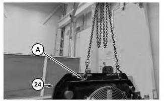
8. Attach tooling (A) and a suitable lifting device to Cooling Package (24). The weight of cooling package (24) is approximately 180 kg (400 lb).
9. Remove bolts (25) from cooling package (24).
10. Remove cooling package (24).
Installation Procedure
1. Install cooling system package (24) in reverse order of removal.
a. Tighten clamps (5), (7), (13), and (14) to a torque of 6 ± 1 N·m (53 ± 9 lb in).
b. Retighten clamps (5), (7), (13), and (14) to a static torque of 4.5 N·m (40 lb in) after no less than 10 minutes.
c. Tighten clamps (19) and (23) to a torque of 4 ± 1 N·m (31 ± 6 lb in).
d. Retighten clamps (19) and (23) to a static torque of 2 N·m (20 lb in) after no less than 10 minutes.
g06076728
g06074805
This is the sample of the manual click on the download link for complete manual