DOWNLOAD LINK
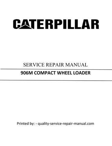
Illustration 6 g01471777
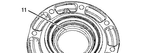
9. Remove seal (14).
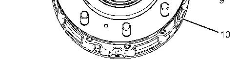
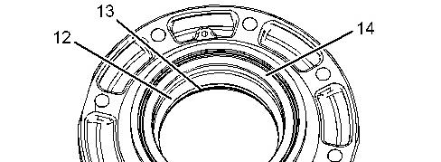
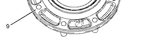
10. Use Tooling (A) and (B) in order to remove bearing cups (12) and (13) from the flange assembly (9).
Note: The springs are under pressure.
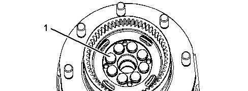
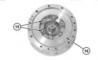
Illustration 7 g01507939
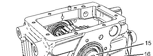
11. Remove six brake adjust kits (15). Remove brake piston (16).
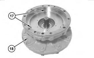
Illustration 8
g01507962
12. Remove three pins (17) from the brake housing (18).
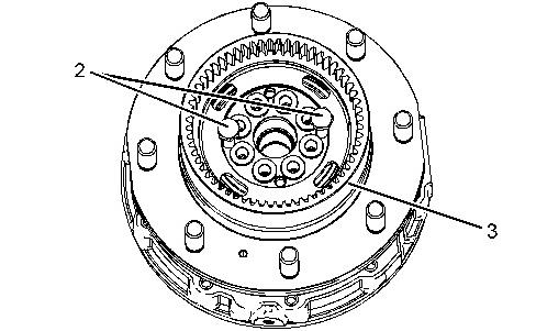
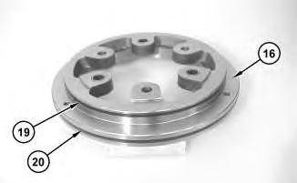
Illustration 9
g01507987
13. Remove seal (19) and (20) from the brake piston (16).
14. Repeat Step 1 through 13 for the other side.
Rights Reserved.
Product: COMPACT WHEEL LOADER
Model: 906M COMPACT WHEEL LOADER H66
Configuration: 906M Compact Wheel Loader H6600001-UP (MACHINE) POWERED BY C3.3B Engine
Disassembly and Assembly
906, 907 and 908 Compact Wheel Loaders Power Train
Transfer Drive Group (Hydrostatic) (High Speed) - Assemble
SMCS - 3159-016-H7; 4350-016-HZ
Assembly Procedure
Table 1 Required Tools
F 4C-9506 Retaining Compound
G - Loctite 401 Bonder AdhesiveH 6V-2012 Depth Micrometer
J 6V-6640 Sealant
K 1P-0510 Driver Gp
M - Loctite 567
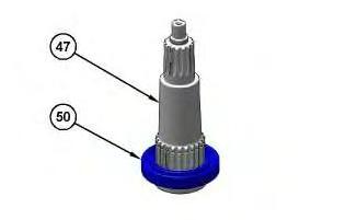
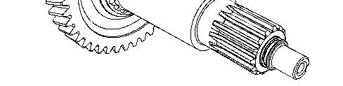
Illustration 1
g06159976
1. Raise the temperature of bearing (50) and install bearing (50) on shaft assembly (47).
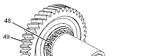
Illustration 2 g01662932
2. Install gear (49) and retaining ring (48).
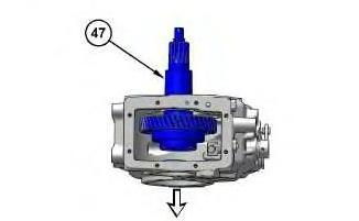
Illustration 3
3. Install shaft assembly (47) through the top of the housing and position the bearing end through the correct opening.
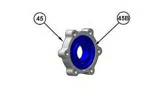
Illustration 4
4. Install bearing (45B) in cover (45).
g06159323
Illustration 5
g06159305
g06159993
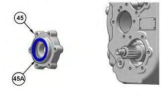
5. Use Tooling (K) to install seal (45A) in cover (45).
Illustration 6
g01662927
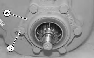
6. Apply Tooling (J) to cover (45). Apply Tooling (M) to bolts (46). Position cover (45). Install bolts (46). Tighten bolts (46) to a torque of 50 N·m (37 lb ft).
Illustration 7
g06160431
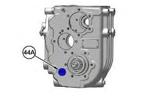
7. Install plug (44A). Tighten plug (44A) to a torque of 60 N·m (44 lb ft).
Illustration 8 g06160420
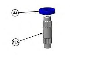
8. Raise the temperature of bearing (43) and install bearing (43) on shaft assembly (43A).
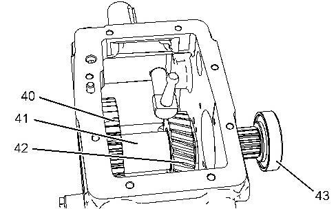
Illustration 9 g01662923
9. As you install shaft assembly (43), install gear (42), spacer (41), gear (40) onto shaft assembly (43).
Illustration 10 g06160489
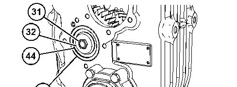
10. Raise the temperature of bearing (44) and install bearing (44). Install race (33). Apply Tooling (E) to bolt (31). Install washer (32) and bolt (31) . Tighten bolt (31) to a torque of 139 N·m (103 lb ft).
Illustration 11
g01662917
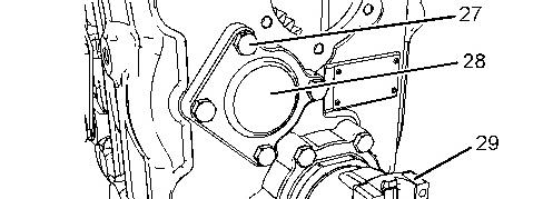
11. Apply Tooling (J) to cover (28). Apply Tooling (M) to bolts (27). Position cover (28) and install bolts (27). Tighten bolts (27) to a torque of 50 N·m (37 lb ft). Install yoke (29). Install the O-ring seals that are on the centering ring. Install the centering ring and ring nut (30). Tighten ring nut (30) to a torque of 190 N·m (140 lb ft).
Illustration 12 g06160765
Illustration 13
g02364559
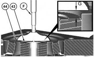
Illustration 14
Cutaway view showing Distance (G).
g02364636
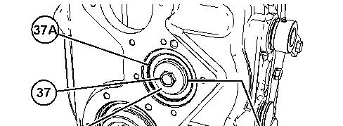
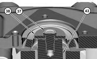
12. Install race (37A). Install bolt (37) and washer (38). Tighten bolt (37) to a torque of 139 N·m (103 lb ft).
13. Remove bolt (37) and washer (38).
14. This step determines the correct shaft preload adjustment for shaft assembly (43). Use Tooling (H) to measure Distance (G). Distance (G) is the measurement from the face of the inner bearing race (44) to the face of shaft assembly (43). The correct shim thickness is determined by subtracting 0.1 mm (0.004 inch) from Distance (G).
15. Apply Tooling (E) to bolt (37). Position shims (39) (not shown), washer (38), and install bolt (37). Tighten bolt (37) to a torque of 139 N·m (103 lb ft).
Illustration 15 g02366796
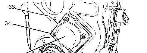
16. Install shims (36) as required to achieve an end play of 0.0508 mm (0.002 inch) on the shaft assembly.
17. Apply Tooling (J) to cover (35). Apply Tooling (M) to bolts (34). Install bolts (34). Tighten bolts (34) to a torque of 23 N·m (16 lb ft).
Illustration 16 g01662916
18. Install bearing (26).
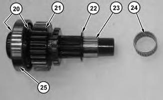
17
19. Install bearing (25). Install retaining rings (20). Install gear (21). Install washer (22). Install bearing race (23). Install needle bearing (24).
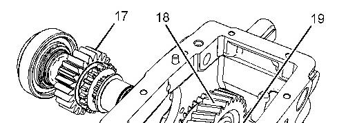
Illustration 18
20. Install gear (18) and spacer (19). Install shaft assembly (17).
Illustration
g01662915
g01662914
Illustration 19 g02367338
Illustration 20 g02367137
Illustration 21 g01662873
21. Install washer (15) and bolt (16). Tighten bolt (16) to a torque of 139 N·m (103 lb ft). Remove washer (15) and bolt (16).
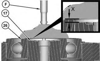
22. This step determines the correct preload adjustment for shaft assembly (17). Use Tooling (H) to measure Distance (X). Distance (X) is the measurement from the face of the inner bearing race to the face of shaft assembly (17). The correct shim thickness is determined by subtracting 0.1 mm (0.004 inch) from Distance (X).
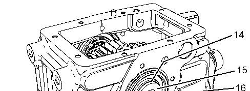
23. Install shims (14) and washer (15). Apply Tooling (E) to bolt (16). Install bolt (16). Tighten bolt (16) to a torque of 139 N·m (103 lb ft).
Illustration 22 g01662913
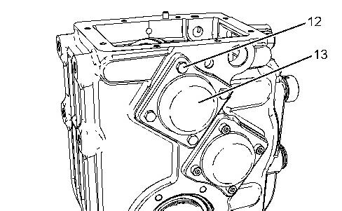
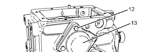
24. Apply Tooling (J) to cover (13). Apply Tooling (M) to bolts (12). Position cover (13). Install bolts (12). Tighten bolt (12) to a torque of 23 N·m (17 lb ft).
Illustration 23
g01620653
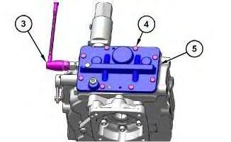
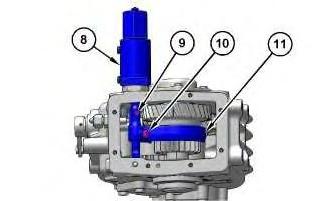
Note: Install shift cylinder (8) with the three detent grooves facing upward.
25. Position fork (11). Apply Tooling (J) to shift cylinder (8). Install shift cylinder (8). Apply Tooling (E) to bolt (10). Install bolt (10). Tighten bolt (10) to a torque of 32 N·m (24 lb ft). Install Tooling (E) to bolt (9). Install the bushing and bolt (9). Tighten bolt (9) to a torque of 5.0 N·m (44.25 lb in).
Illustration 24
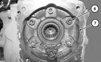
g01662853
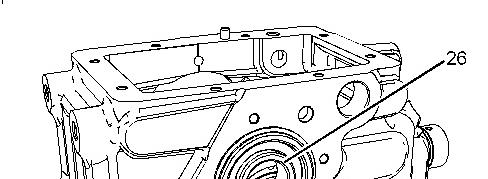
26. Apply Tooling (J) to flange (7). Apply Tooling (M) to bolts (6). Position flange (7). Install bolts (6). Tighten bolt (37) to a torque of 50 N·m (37 lb ft).
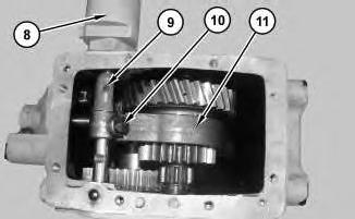
25
27. Apply Tooling (J) to cover (5). Install cover (5). Install bolts (4). Apply Tooling (M) to switch assembly (3). Install switch assembly (3).
Illustration 26
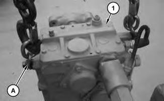
g01620410
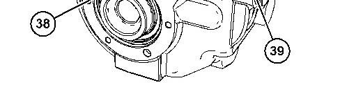
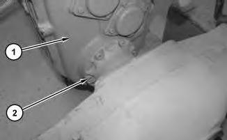
28. Install Tooling (A) to hydrostatic transfer drive (1).
Illustration 27
g01620418
Illustration
g06158367
29. Position hydrostatic transfer drive (1). Install bolts (2).
Copyright 1993 - 2021 Caterpillar Inc. All Rights Reserved. Private Network For SIS Licensees.
Wed Mar 17 11:32:49 UTC+0530 2021
Product: COMPACT WHEEL LOADER
Model: 906M COMPACT WHEEL LOADER H66
Configuration: 906M Compact Wheel Loader H6600001-UP (MACHINE) POWERED BY C3.3B Engine
Disassembly and Assembly 906, 907 and 908 Compact Wheel Loaders Power Train
Transfer Drive Group (Hydrostatic) (High Speed)Disassemble
Disassembly Procedure Table 1
Start By:
a. Remove the Drive Shaft. Refer to Disassembly and Assembly Manual, "Drive Shaft - Remove and Install".
b. Remove the Piston Motor. Refer to Disassembly and Assembly Manual, "Piston Motor (Hydrostatic) - Remove".
NOTICE
Care must be taken to ensure that fluids are contained during performance of inspection, maintenance, testing, adjusting, and repair of the product. Be prepared to collect the fluid with suitable containers before opening any compartment or disassembling any component containing fluids.
Refer to Special Publication, NENG2500, "Dealer Service Tool Catalog" for tools and supplies suitable to collect and contain fluids on Cat® products.
Dispose of all fluids according to local regulations and mandates.
Personal injury can result from hydraulic oil pressure and hot oil.
Hydraulic oil pressure can remain in the hydraulic system after the engine has been stopped. Serious injury can be caused if this pressure is not released before any service is done on the hydraulic system.
Make sure all of the work tools have been lowered to the ground, and the oil is cool before removing any components or lines. Remove the oil filler cap only when the engine is stopped, and the filler cap is cool enough to touch with your bare hand.
1. Drain the transfer drive oil into a suitable container. The capacity of the transfer drive is 1.3 L (0.3 US gal).
Illustration 1
g01620410
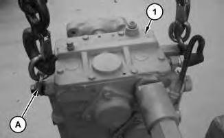
2. Install Tooling (A) to transfer drive group (1).
Illustration 2
g01620418
3. Remove bolts (2) to remove transfer drive group (1).
Illustration 3
g06158367
4. Remove switch assembly (3). Remove bolts (4). Use bolts (4) in pusher holes to remove cover (5).
Illustration 4
5. Remove bolts (6). Remove flange (7).
g01662853
Illustration 5
g06158377
6. Remove bolt (9) and the bushing. Remove bolt (10). Remove shift cylinder (8). Remove fork (11).
Illustration 6 g01662913
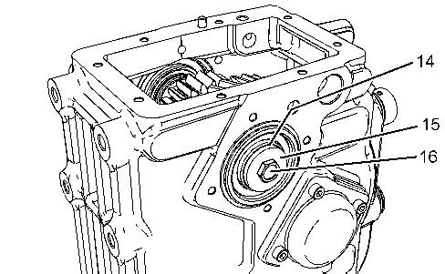
7. Remove bolts (12). Remove cover (13).
7 g01662873
8. Remove bolt (16). Remove washer (15). Remove shims (14).
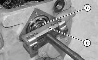
Illustration
Illustration 8
9. Install Tooling (C) and Tooling (B).
g01621043
Illustration 9 g01662914
10. Remove shaft assembly (17). Remove gear (18) and spacer (19).
This is the sample of the manual click on the download link for complete manual