

Product: BACKHOE LOADER
Model: 430F BACKHOE LOADER RGS
Configuration: 430F Backhoe Loaders RGS00001-UP (MACHINE) POWERED BY C4.4 Engine
Operation and Maintenance Manual 416F, 420F and 430F Backhoe Loaders
Foreword
Literature Information
s00037320
Product: BACKHOE LOADER
Model: 430F BACKHOE LOADER RGS
Configuration: 430F Backhoe Loaders RGS00001-UP (MACHINE) POWERED BY C4.4 Engine
Operation and Maintenance Manual 416F, 420F and 430F Backhoe Loaders
Foreword

This is the sample of the manual Click on the download link for complete Manual

Product: BACKHOE LOADER
Model: 430F BACKHOE LOADER RGS
Configuration: 430F Backhoe Loaders RGS00001-UP (MACHINE) POWERED BY C4.4 Engine
Operation and Maintenance Manual
416F, 420F and 430F Backhoe Loaders
Media Number -SEBU8715-05
Publication Date -01/07/2013
SMCS - 3278-070-BRE; 3278-510-BRE
Date Updated -22/04/2016
i02436158
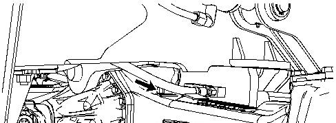

Illustration 1 g01216797
The front axle breather is located on the top right side of the differential housing.
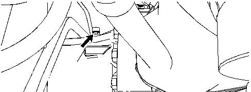
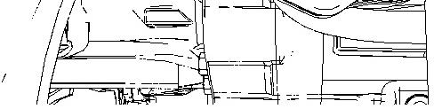
Illustration 2 g01216798
The rear axle breather is located to the left of the differential housing.
1. Clean the area around the breathers. Remove the breather from the front axle.
2. Wash the breather in clean nonflammable solvent. Wipe the breather dry and check the breather for damage.
3. Install the clean breather back into the axle. Replace the breather if the breather is damaged.
Note: Make sure that the slot in the breather is parallel to the axle housing.
Product: BACKHOE LOADER
Model: 430F BACKHOE LOADER RGS
Configuration: 430F Backhoe Loaders RGS00001-UP (MACHINE) POWERED BY C4.4 Engine
Operation and Maintenance Manual
416F, 420F and 430F Backhoe Loaders
Media Number -SEBU8715-05 Publication Date -01/07/2013 Date Updated -22/04/2016
SMCS - 6501-086-BD; 6502-086-BD; 6503-086-BD; 6511-086-BD; 6512-086-BD; 6533-086BD; 7562-086-BD
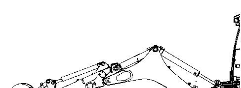

Illustration 1 g01194613
Position the backhoe into the service position that is shown above. Lower the bucket to the ground. Relieve the hydraulic pressure.


2 g01194615
Apply lubricant to the grease fitting (1) for the rod end of the stick cylinder.
Apply lubricant to the grease fitting (2) for the head end of the boom cylinder and the head end of the stick cylinder.
Apply lubricant to the grease fitting (3) for the rod end of the boom cylinder.
Apply lubricant to the grease fitting (4) for the boom pivot. There is one grease fitting on each side of the machine.
3 g01194617
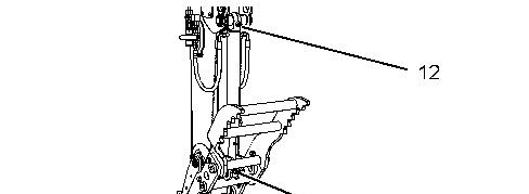
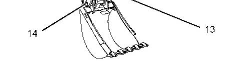
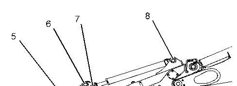
Illustration 4 g01491621
Apply lubricant to the grease fitting (5) for the bucket pivot pin.
Apply lubricant to the grease fitting (6) for the link.
Apply lubricant to the grease fitting (7) for the rod end of the bucket cylinder.
Apply lubricant to the grease fitting (8) for the head end of the bucket cylinder.
Apply lubricant to the grease fitting (9) for the pivot pin for the stick.
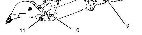
Apply lubricant to the grease fitting (10) for the pivot pin. There is one grease fitting on each side of the machine.
Apply lubricant to the grease fitting (11) for the pivot pin.
Apply lubricant to the grease fitting (12) for the head end of the thumb cylinder.
Apply lubricant to the grease fitting (13) for the rod end of the thumb cylinder.
Apply lubricant to the grease fitting (14) for the pivot pin on each side of the thumb.
There is a total of 21 grease fittings. Copyright 1993 - 2023 Caterpillar Inc.
Product: BACKHOE LOADER
Model: 430F BACKHOE LOADER RGS
Configuration: 430F Backhoe Loaders RGS00001-UP (MACHINE) POWERED BY C4.4 Engine
Operation and Maintenance Manual
416F, 420F and 430F Backhoe Loaders
Media Number -SEBU8715-05
Publication Date -01/07/2013
SMCS - 5258-086-LX
Date Updated -22/04/2016
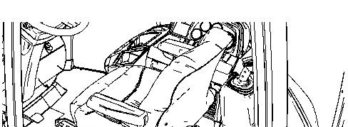
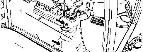

Illustration 1 g01450004
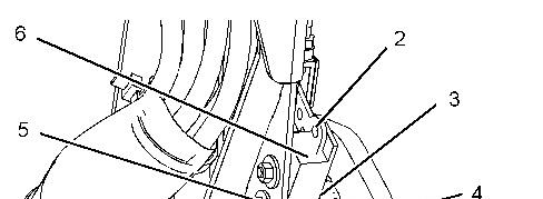
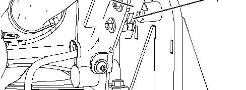
Illustration 2 g01450005
1. Remove the three bolts and remove the console (1).
2. Place the latch in the closed position.
3. Apply 242-6990 Lubricant onto the following:
Pivot for the release lever (2)
Axle for the catch (3)
Rotor axle (4)
Notches and catch for the rotor (5)
Contact for the release lever (6)
4. Cycle the latch two times.
5. Repeat steps 1 through 4.
Product: BACKHOE LOADER
Model: 430F BACKHOE LOADER RGS
Configuration: 430F Backhoe Loaders RGS00001-UP (MACHINE) POWERED BY C4.4 Engine
Operation and Maintenance Manual
416F, 420F and 430F Backhoe Loaders
Media Number -SEBU8715-05
Publication Date -01/07/2013
SMCS - 7406-081
Turn the engine start switch key to ON in order to perform the test.
Date Updated -22/04/2016
Apply the service brake. Move the transmission direction control lever to REVERSE position.
The backup alarm should immediately sound. The backup alarm will continue to sound until the transmission direction control lever is moved to the NEUTRAL position or to the FORWARD position.
Copyright 1993 - 2023 Caterpillar Inc. All Rights Reserved. Private Network For SIS Licensees. Sat Feb 18 21:31:18 UTC+0530 2023
Product: BACKHOE LOADER
Model: 430F BACKHOE LOADER RGS
Configuration: 430F Backhoe Loaders RGS00001-UP (MACHINE) POWERED BY C4.4 Engine
Operation and Maintenance Manual
416F, 420F and 430F Backhoe Loaders
Media Number -SEBU8715-05
SMCS - 1401-040; 1401-510; 1402-040; 1402-510
-22/04/2016
i01833495
1. Turn the engine start switch to the OFF position. Turn all switches to the OFF position.
2. Disconnect the negative battery cable from the frame.
Note: Do not allow the disconnected battery cable to contact the frame of the machine.
3. Disconnect the negative battery cable at the battery.
4. Inspect the battery terminals and inspect the battery cables. Keep the terminals clean and keep the terminals coated with petroleum jelly.
5. Perform the necessary repairs. Replace the cable or the battery, as needed.
6. Connect the negative battery cable at the battery.
7. Connect the battery cable to the frame of the machine.
8. Install the engine start switch key.
Copyright 1993 - 2023 Caterpillar Inc. All Rights Reserved. Private Network For SIS Licensees. Sat Feb 18 21:32:42 UTC+0530 2023
Product: BACKHOE LOADER
Model: 430F BACKHOE LOADER RGS
Configuration: 430F Backhoe Loaders RGS00001-UP (MACHINE) POWERED BY C4.4 Engine
Operation and Maintenance Manual
416F, 420F and 430F Backhoe Loaders
Media Number -SEBU8715-05
Publication Date -01/07/2013
SMCS - 1357-510; 1357-025; 1357-040
Date Updated -22/04/2016
i06899518


Illustration 1 g03507446
Belt Routing Film: Machines with A/C


2 g03518922
Belt Routing Film: Machines without A/C
If new belts are installed, check belt adjustment after 30 minutes of operation. For multiple belt drive applications, always replace the belts in matched sets. Replacing only one belt of a matched set will cause the new belt to carry more load because the older belts are stretched. The additional load on the new belt could cause the new belt to break.
1. Install the lift cylinder brace. Refer to Operation and Maintenance Manual, "Lift Cylinder Brace - Connect and Disconnect" for more information.
2. Remove the engine access panel on the left side of the machine.
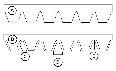
3 g06114636
3. Inspect the condition of the serpentine belt. Over time the belt ribs will lose material (C). The space between the ribs will increase (D). The loss of material will cause the pulley sheave to contact the belt valley. This will lead to belt slippage and accelerated wear (E). Replace the belt if the belt is worn or frayed.
Note: The serpentine belt is the self-adjusting type. There is no adjustment of the tension.
4. Close the engine access door. Copyright 1993 - 2023 Caterpillar Inc. All Rights Reserved. Private Network For SIS Licensees. Sat Feb 18 21:32:58 UTC+0530 2023
Product: BACKHOE LOADER
Model: 430F BACKHOE LOADER RGS
Configuration: 430F Backhoe Loaders RGS00001-UP (MACHINE) POWERED BY C4.4 Engine
Operation and Maintenance Manual
416F, 420F and 430F Backhoe Loaders
Media Number -SEBU8715-05
SMCS - 4251-081; 4267-081
Date -01/07/2013 Date Updated -22/04/2016
Check the area around the machine. Make sure that the machine is clear of personnel and clear of obstacles.
Test the brakes on a dry, level surface.
Fasten the seat belt before you test the brakes.
The following test is used to determine if the service brake is functional. This test is not intended to measure the maximum brake holding effort. The brake holding effort that is required to sustain a machine at a specific engine rpm varies depending on the machine. The variations are the differences in the engine setting, in the power train efficiency, and in the brake holding ability, etc.
1. Start the engine. Raise the bucket slightly.
2. Apply the service brake. Release the parking brake.
3. Move the transmission control lever to THIRD SPEED FORWARD.
4. Gradually increase the engine speed to high idle. The machine should not move.
If the machine begins to move, reduce the engine speed immediately and engage the parking brake.
5. Reduce the engine speed to low idle. Move the transmission to NEUTRAL. Engage the parking brake. Lower the bucket to the ground. Stop the engine.
If the machine moved while testing the brakes, contact your Caterpillar dealer. Have the dealer inspect and, if necessary, repair the service brake before returning the machine to operation.
Check the area around the machine. Make sure that the machine is clear of personnel and clear of obstacles.
Test the brakes on a dry, level surface.
Fasten the seat belt before you test the brakes.
The following tests are used to determine if the parking brake is functional. These tests are not intended to measure the maximum brake holding effort. The brake holding effort that is required to sustain a machine at a specific engine rpm varies depending on the machine. The variations are the differences in the engine setting, in the power train efficiency, and in the brake holding ability, etc.
1. Start the engine. Raise the bucket slightly.
2. Engage the parking brake.
3. Move the transmission control lever to THIRD SPEED FORWARD, then to NEUTRAL, then back to THIRD SPEED FORWARD.
Note: The parking brake indicator light should come on and the parking brake alarm should sound if machine ground speed is above 6 km/h (3.7 mph) with the secondary brake still engaged.
4. Gradually increase the engine speed to high idle. The machine should not move.
If the machine begins to move, reduce the engine speed immediately and apply the service brake pedal.
5. Reduce the engine speed. Move the transmission to NEUTRAL. Lower the bucket to the ground. Stop the engine.
If the machine moved while testing the brakes, contact your Caterpillar dealer.
Have the dealer inspect and, if necessary, repair the parking brakes before returning the machine to operation.
Copyright 1993 - 2023 Caterpillar Inc. All Rights Reserved. Private Network For SIS Licensees. Sat Feb 18 21:33:10 UTC+0530 2023
Product: BACKHOE LOADER
Model: 430F BACKHOE LOADER RGS
Configuration: 430F Backhoe Loaders RGS00001-UP (MACHINE) POWERED BY C4.4 Engine
Operation and Maintenance Manual
416F, 420F and 430F Backhoe Loaders
Media Number -SEBU8715-05 Publication Date -01/07/2013 Date Updated -22/04/2016
SMCS - 6801-040; 6801-510
Personal injury or death can result from bucket falling.
Block the bucket before changing bucket cutting edges.
1. Raise the bucket. Place a block under the bucket.
2. Lower the bucket to the blocking.
Do not block up the bucket too high. Block up the bucket so that the bucket is high enough to remove the cutting edges and the end bits.
3. Remove the bolts. Remove the cutting edge and the end bits.
4. Clean the contact surfaces.
5. Use the opposite side of the cutting edge, if this side is not worn.
6. Install a new cutting edge, if both edges are worn.
7. Install the bolts. Tighten the bolts to the specified torque.
8. Raise the bucket. Remove the blocks.
9. Lower the bucket to the ground.
10. After a few hours of operation, check the bolts for proper torque.
Product: BACKHOE LOADER
Model: 430F BACKHOE LOADER RGS
Configuration: 430F Backhoe Loaders RGS00001-UP (MACHINE) POWERED BY C4.4 Engine
Operation and Maintenance Manual
416F, 420F and 430F Backhoe Loaders
Media Number -SEBU8715-05
Publication Date -01/07/2013
SMCS - 6805-040; 6805-510
Date Updated -22/04/2016
Personal injury or death can result from the bucket falling.
Block the bucket before changing bucket tips.


Illustration 1 g00101352
(1) This tip is usable. (2) This tip should be replaced. (3) This tip has been overworn.
Check the bucket tips for wear. If the bucket tip has a hole, replace the bucket tip.
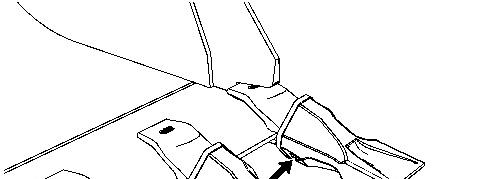
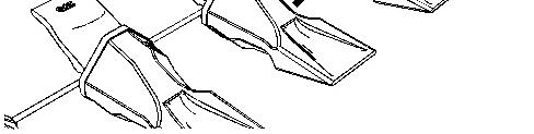
Illustration 2 g01272671
1. Drive the pin out of the bucket tip from the retainer side of the bucket tip. Remove the bucket tip and the retainer.
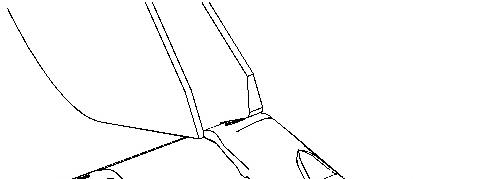
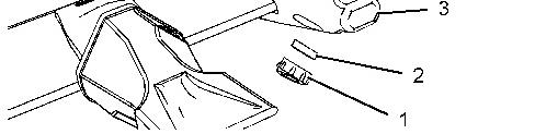
Illustration 3 g01272854
(1) Retaining washer (2) Retainer (3) Adapter
2. Clean the adapter and the pin.
3. Fit retainer (2) into retaining washer (1). Install this assembly into the groove that is in the side of adapter (3).
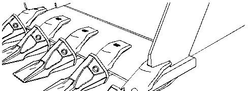

Illustration 4 g01272859
4. Install the new bucket tip or the rotated bucket tip onto the adapter. To allow greater penetration or less penetration, the bucket tip may be rotated by 180 degrees.
5. From the other side of the retainer, drive the pin through the bucket tip, the adapter, and the retainer.
6. After you drive the pin, make sure that the retainer fits snugly into the pin groove.
2023
This is the sample of the manual Click on the download link for complete Manual