

Product: BACKHOE LOADER
Model: 428D BACKHOE LOADER BMT
Configuration: 428D Backhoe Loader BMT01618-03227 (MACHINE) POWERED BY 3054 Engine
Operation and Maintenance Manual 424D, 428D and 438D Backhoe Loaders
Media Number -SEBU7400-02
Foreword
Literature Information

This is the sample of the manual Click on the download link for complete Manual

Product: BACKHOE LOADER
Model: 428D BACKHOE LOADER BMT
Configuration: 428D Backhoe Loader BMT01618-03227 (MACHINE) POWERED BY 3054 Engine
Operation and Maintenance Manual
424D, 428D and 438D Backhoe Loaders
Media Number -SEBU7400-02
Publication Date -01/06/2006
Accelerator Control
SMCS - 1265; 1276
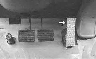
Illustration 1
Date Updated -28/06/2006
i01453312
g00732046
Accelerator Pedal - Push down the pedal in order to increase travel speed. Release the pedal in order to decrease travel speed. The accelerator pedal will return to the low idle setting.
Use the pedal to reduce engine rpm for directional shifts when you use the loader.
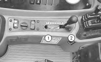
Illustration 2 g00730721
Accelerator Lever - This lever controls the engine speed for backhoe operation.
Operate the machine in the green operating range on the tachometer.

High Idle - Move the lever to position (1) for a faster idle speed.

Low Idle - Move the lever to position (2) for a lower idle speed.
For roading or loader operation, keep the lever in the position (2). Use the accelerator pedal to change the engine speed.
Note: The maximum recommended operating engine speed is 2100 rpm. Copyright 1993 - 2022 Caterpillar Inc. All Rights Reserved. Private Network For SIS Licensees.
Mon Aug 1 16:42:44 UTC+0530 2022
Product: BACKHOE LOADER
Model: 428D BACKHOE LOADER BMT
Configuration: 428D Backhoe Loader BMT01618-03227 (MACHINE) POWERED BY 3054 Engine
Operation and Maintenance Manual
424D, 428D and 438D Backhoe Loaders
Media Number -SEBU7400-02
Publication Date -01/06/2006
Date Updated -28/06/2006
Alert Indicators
SMCS - 7450; 7451
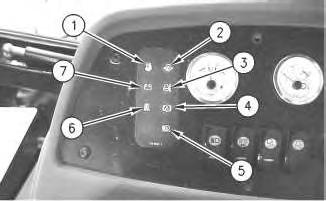
Illustration 1
g00731962

Fuel System Water Separator (1) (If Equipped) - The alert indicator indicates a plugged fuel/water separator. If this alert indicator comes on during operation, stop the machine immediately and engage the parking brake. Stop the engine and investigate the cause of the fault.

Engine Oil Pressure (2) - The alert indicator will light when the engine oil pressure is low. If this alert indicator comes on, stop the machine immediately. Stop the engine and investigate the cause.

Engine Coolant (3) - The alert indicator will light and an audible alarm will sound when the engine coolant temperature is too high. If this alert indicator comes on, stop the machine immediately. Stop the engine and investigate the cause.

Brake Oil Level (4) - The alert indicator will light and an audible alarm will sound when the brake reservoir oil is low. If this alert indicator comes on, stop the machine immediately. Investigate the cause and add oil to the correct level. Do not operate the machine if the indicator light stays on.

Air Filter Indicator (5) (If Equipped) - The alert indicator will light when the air filter becomes clogged. If this alert indicator comes on, stop the machine and investigate the cause.

Hydraulic Oil Filter (6) (If Equipped) - The alert indicator indicates a plugged hydraulic oil filter. If this alert indicator flashes during operation, stop the machine immediately and engage the parking brake. Stop the engine and investigate the cause of the fault.

Charging System (7) - The alert indicator comes on if there is a malfunction in the electrical system. If this alert indicator comes on, the system voltage is too high for normal machine operation or too low for normal machine operation.
If electrical loads (air conditioning and/or lighting) are high and the engine speed is near idle, increase the engine speed to high idle. This will generate more output from the alternator. If the alert indicator for the electrical system turns off within one minute, the electrical system is probably operating in a normal manner. However, the electrical system may be overloaded during periods of low engine speeds.
Modify the operating cycle in order to prevent overloading the electrical system and discharging the batteries.
Low idle must be set correctly. Adjust for the high side of the Low Idle specification while the most often used electrical loads are turned on. In order to reduce the loads, use the Medium fan speed instead of the High fan speed.
If this procedure does not cause the alert indicator to turn off, move to a convenient location. Investigate the cause (loose alternator belt, broken alternator belt, faulty batteries, etc).
If the engine speed is near operating speeds and if the electrical loads are light, the alert indicator may remain on. If the alert indicator remains on, move to a convenient location. Investigate the cause (loose alternator belt, broken alternator belt, faulty batteries, etc).
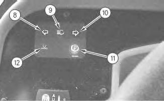

Left Turn Signal (8) - The alert indicator will flash when the left turn signal is activated.

High Beams (9) - The alert indicator will light when you press the top of the dimmer switch. The alert indicator should go out when you press the bottom of the dimmer switch.

Right Turn Signal (10) - The alert indicator will flash when the right turn signal is activated.

Parking Brake (11) - The alert indicator will light and an audible alarm will sound when the parking brake is engaged and the transmission is put into forward or reverse. The
alert indicator should come on during start-up. The alert indicator should go out when the parking brake is released.

Ride Control (12) - The alert indicator will light when the ride control is activated.
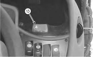
Illustration 3

g00735342
Hazard (13) - The alert indicator will flash and the turn signals will flash when the hazard flashers are activated.
Copyright 1993 - 2022 Caterpillar Inc. All Rights Reserved. Private Network For SIS Licensees.
Mon Aug 1 16:38:37 UTC+0530 2022
Product: BACKHOE LOADER
Model: 428D BACKHOE LOADER BMT
Configuration: 428D Backhoe Loader BMT01618-03227 (MACHINE) POWERED BY 3054 Engine
Operation and Maintenance Manual 424D, 428D and 438D Backhoe Loaders
Media Number -SEBU7400-02
Publication Date -01/06/2006
Date Updated -28/06/2006
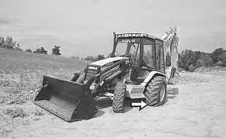
All Wheel Drive and All Wheel Braking Control - If Equipped
SMCS - 4250; 4810
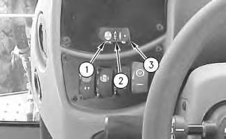
Illustration 1

g00729756
All Wheel Drive (1) - Push the left side of the switch to the ON position in order to activate all wheel drive.
All Wheel Drive can be activated anytime when additional traction is desired.
All Wheel Drive should always be activated when you are operating the machine on a slope.

All Wheel Drive Braking (2) - Place the switch in the middle position in order to enable the All Wheel Drive Braking. The machine will operate in two-wheel drive until you push on the brake pedals. Pushing on the brake
pedals will activate the All Wheel Drive.
Note: For machines that are equipped with two-wheel steer, you must press on both of the brake pedals at the same time in order to enable the All Wheel Drive Braking. Steering using the brakes is still possible for two-wheel steer machines, when you press one brake pedal.
All Wheel Drive Braking should always be activated when you are roading the machine.

OFF (3) - Push the right side of the switch to the OFF position for twowheel drive. The All Wheel Drive Braking is deactivated when the switch is in this position.
Copyright 1993 - 2022 Caterpillar Inc.
Rights Reserved.
Network For SIS Licensees. Mon Aug 1 16:44:18 UTC+0530 2022
Product: BACKHOE LOADER
Model: 428D BACKHOE LOADER BMT
Configuration: 428D Backhoe Loader BMT01618-03227 (MACHINE) POWERED BY 3054 Engine
Operation and Maintenance Manual 424D, 428D and 438D Backhoe Loaders
Media Number -SEBU7400-02
Publication Date -01/06/2006
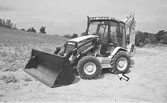
All Wheel Drive Control - If Equipped
SMCS - 4810
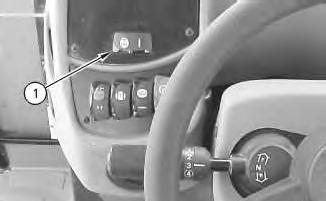
Illustration 1 g00731986
All Wheel Drive (1) - Push the left side of the switch in order to activate all wheel drive. Push the right side of the switch for two-wheel drive mode.
Date Updated -28/06/2006
All Wheel Drive can be activated anytime when additional traction is desired.
All Wheel Drive should always be activated when you are operating the machine on a slope.
Copyright 1993 - 2022 Caterpillar Inc. All Rights Reserved. Private Network For SIS Licensees.
Mon Aug 1 16:44:07 UTC+0530 2022
Product: BACKHOE LOADER
Model: 428D BACKHOE LOADER BMT
Configuration: 428D Backhoe Loader BMT01618-03227 (MACHINE) POWERED BY 3054 Engine
Operation and Maintenance Manual
424D, 428D and 438D Backhoe Loaders
Media Number -SEBU7400-02
Publication Date -01/06/2006
All Wheel Steer Control - If Equipped
SMCS - 7332
Date Updated -28/06/2006
Personal injury or death can result if the machine is roaded in any mode other than front wheel steer.
Always road the machine with the rear wheels centered and the machine in the front wheel steer mode.
The All Wheel Steer (AWS) has three steering modes: All Wheel Steer, Two-Wheel Steer and an Independent Rear Maneuvering mode. When you operate the machine for the first time, become familiar with the three modes by trying each one. This should be done in an area that is clear of personnel and of obstacles.
2
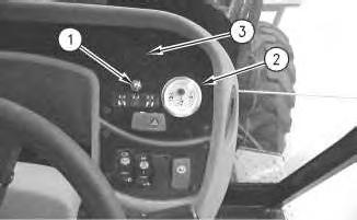
g00756061
The All Wheel Steer mode consists of the following components:
• an All Wheel Steer switch (1) that allows the operator to choose from the three modes
• a rear axle position gauge (2)
• an alert indicator (3)
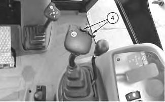
• an independent rear maneuvering switch (4)
Three modes provide maximum machine performance under various conditions at the job site.
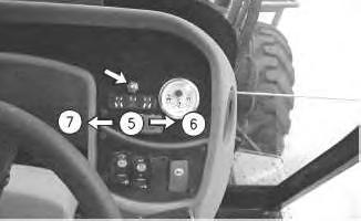
Illustration 3

g00756058
Two-Wheel Steer - The Two-Wheel Steer mode (5) offers the capability to operate the machine on the road. The Two-Wheel Steer mode is used when additional maneuvering capability is not needed. Only the front axle is used to steer the machine. Use this mode when you are roading the machine.

When you are operating the machine in this mode the indicator light (3) will not be on.
All Wheel Steer - The All Wheel Steer mode (6) allows the operator to choose independent rear maneuvering for positioning the rear axle and for controlling the rear axle. The switch that is located on the loader control lever is used for positioning and for controlling the rear axle. When you are operating the machine in the All Wheel Steer mode, the indicator light (3) will be on.
4
Pull the independent rear maneuvering switch (4) to the right. The wheels will move the back of the machine to the left when the machine is moving in a forward direction.
5
Pull the independent rear maneuvering switch (4) to the left. The wheels will move the back of the machine to the right when the machine is moving in a forward direction.


Illustration 6 g00282686
Position the front wheels and back wheels in opposite directions in order to maneuver around a very tight corner.
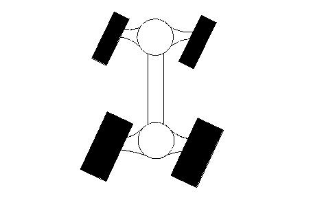
Illustration 7 g00282687
Position the front wheels and back wheels in the same direction for crab steering.

Circle Steer Mode - The Circle Steer Mode (7) provides reduced turning radii and tighter operation in confined spaces. The front and rear axles are used to steer the machine. When you are operating the machine in the Circle Steer mode, the indicator light (3) will come on.
NOTICE
Before changing from one steering mode to another, always center both the front and rear wheels.
Before you return to the Two-Wheel Steer mode or to the Circle Steer mode, the front wheels and rear wheels must be centered. Observe the rear axle position gauge (2) on the front console. Use the independent rear maneuvering switch (4) to center the rear wheels until the zero position is obtained. Then, move the All Wheel Steer switch to the desired mode.
Copyright 1993 - 2022 Caterpillar Inc. All Rights Reserved. Private Network For SIS Licensees.
Mon Aug 1 16:45:04 UTC+0530 2022
Product: BACKHOE LOADER
Model: 428D BACKHOE LOADER BMT
Configuration: 428D Backhoe Loader BMT01618-03227 (MACHINE) POWERED BY 3054 Engine
Operation and Maintenance Manual
424D, 428D and 438D Backhoe Loaders
Media Number -SEBU7400-02
Publication Date -01/06/2006
Alternate
Exit
SMCS - 7310
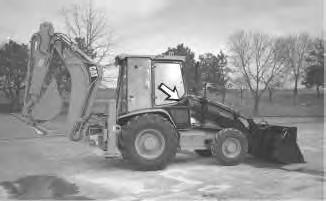
Illustration 1
Date Updated -28/06/2006
i01441067
g00754767
The cab door on the right side of the machine serves as an alternate exit. The cab door can be opened from the inside or from the outside. Pull the door latch on the outside of the cab door in order to open the cab door from the outside.
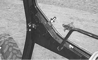
Illustration 2
Move the lever on the inside of cab door in order to unlatch the cab door and open the cab door from the inside.
Copyright 1993 - 2022 Caterpillar Inc.
All Rights Reserved.
Private Network For SIS Licensees.
Mon Aug 1 16:42:10 UTC+0530 2022
Product: BACKHOE LOADER
Model: 428D BACKHOE LOADER BMT
Configuration: 428D Backhoe Loader BMT01618-03227 (MACHINE) POWERED BY 3054 Engine
Operation and Maintenance Manual
424D, 428D and 438D Backhoe Loaders
Media Number -SEBU7400-02
Publication Date -01/06/2006
Autoshift Control - If Equipped
SMCS - 1408; 3168; 4800; 7451-ZS
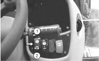
Illustration 1 g00733821
(1) Automatic Mode
(2) Manual Mode
Automatic Mode (1) - Push the top of the switch for the autoshift function in the automatic mode. Push the top of the switch prior to shifting the transmission into forward or reverse in order to activate the autoshift function. The operator selects the highest desired gear for the transmission with the transmission shift lever. The
Date Updated -28/06/2006
control will then select the proper transmission gear according to the ground speed of the machine. Third gear may be skipped in the automatic mode under certain circumstances.
Manual Mode (2) - Press the bottom of the switch in order to prevent the transmission from automatically shifting into fifth gear when the transmission is in fourth gear. The position is also used for the manual mode of the transmission control.
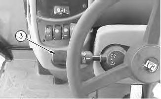
2
g00755953
The manual mode allows the operator to select the desired speed and the desired direction of the machine with the transmission shift lever (3).
Copyright 1993 - 2022 Caterpillar Inc. All Rights Reserved. Private Network For SIS Licensees.
Mon Aug 1 16:43:22 UTC+0530 2022
Product: BACKHOE LOADER
Model: 428D BACKHOE LOADER BMT
Configuration: 428D Backhoe Loader BMT01618-03227 (MACHINE) POWERED BY 3054 Engine
Operation and Maintenance Manual
424D, 428D and 438D Backhoe Loaders
Media Number -SEBU7400-02
Publication Date -01/06/2006
Date Updated -28/06/2006
Backhoe Auxiliary Control (Foot Operated) - If Equipped
SMCS - 5063
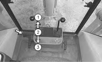
Illustration 1
g00733499
The auxiliary pedal is located on the left side of the console.
Use the auxiliary pedal in order to pressurize the hydraulic lines of a work tool.
Push down on the toe end of the pedal to position (1) in order to pressurize the hydraulic line on the right side of the stick.
HOLD (2) - The pedal will return to the HOLD position when the pedal is released from position (1) or released from position (3) .
Push down on the heel end of the pedal to position (3) in order to pressurize the hydraulic line on the left side of the stick.
Copyright 1993 - 2022 Caterpillar Inc. All Rights Reserved.
Private Network For SIS Licensees.
Mon Aug 1 16:46:03 UTC+0530 2022
Product: BACKHOE LOADER
Model: 428D BACKHOE LOADER BMT
Configuration: 428D Backhoe Loader BMT01618-03227 (MACHINE) POWERED BY 3054 Engine
Operation and Maintenance Manual
424D, 428D and 438D Backhoe Loaders
Media Number -SEBU7400-02
Publication Date -01/06/2006
Date Updated -28/06/2006
Backhoe Extendable Stick Control (Foot Operated)
SMCS - 5063; 5474
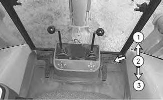
Illustration 1
g00733497
The pedal for the extendable stick is located on the right side of the console.

STICK EXTEND (1) - Push down on the toe end of the pedal in order to extend the stick. Push down on the toe end of the pedal for additional reach with the stick.
HOLD (2) - The pedal will return to the HOLD position when the pedal is released from the STICK EXTEND position or from the STICK RETRACT position. Stick movement will stop.

STICK RETRACT (3) - Push down on the heel of the pedal in order to retract the stick.
This is the sample of the manual Click on the download link for complete Manual