

Product: BACKHOE LOADER
Model: 424D BACKHOE LOADER RXA
Configuration: 424D Backhoe Loader RXA00001-UP (MACHINE) POWERED BY 3054C Engine
Operation and Maintenance Manual
416D, 420D, 424D, 428D, 430D, 432D and 442D Backhoe Loaders
Axle Breathers - Clean/Replace
SMCS - 3278-070-BRE; 3278-510-BRE
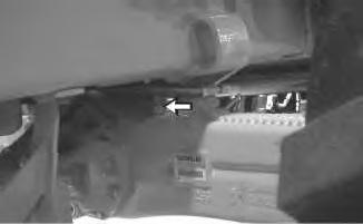
Illustration 1 g00833319
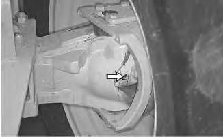
The front axle breather is located on the top right side of the differential housing.
1. Clean the area around the breathers. Remove the breather from the front axle.
Note: Do not turn the adapter when you remove the breather.
i01981945
2. Wash the breather in clean nonflammable solvent. Wipe the breather dry and check the breather for damage.
3. Install the clean breather back into the axle. Replace the breather if the breather is damaged.
Note: If the adapter is turned make sure that the slot in the adapter is parallel to the axle housing.
Copyright 1993 - 2022 Caterpillar Inc. All Rights Reserved.
Private Network For SIS Licensees.
Thu Jun 30 15:56:49 UTC+0530 2022
Product: BACKHOE LOADER
Model: 424D BACKHOE LOADER RXA
Configuration: 424D Backhoe Loader RXA00001-UP (MACHINE) POWERED BY 3054C Engine
Operation and Maintenance Manual
416D, 420D, 424D, 428D, 430D, 432D and 442D Backhoe Loaders Media Number -SEBU7821-06
Axle Universal Joint (Rear) - Lubricate - All Wheel Steer
SMCS - 3251
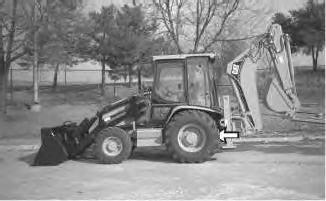
Illustration 1
g00753030
i01437649
This is the sample of the manual Click on the download link for complete Manual
2
Apply lubricant to the grease fittings for the universal joints of each drive shaft to the final drives. There are two grease fittings for each universal joint.
Copyright 1993 - 2022 Caterpillar Inc. All Rights Reserved. Private Network For SIS Licensees. Thu Jun 30 15:57:37 UTC+0530 2022
Product: BACKHOE LOADER
Model: 424D BACKHOE LOADER RXA
Configuration: 424D Backhoe Loader RXA00001-UP (MACHINE) POWERED BY 3054C Engine
Operation and Maintenance Manual
416D, 420D, 424D, 428D, 430D, 432D and 442D Backhoe Loaders
Backhoe Boom, Stick, Bucket, and Cylinder BearingsLubricate
SMCS - 6501; 6502; 6503; 6510; 6511; 6512; 6513; 6533
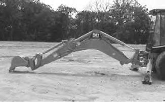
Illustration 1
g00723263
Position the backhoe into the service position that is shown above.
i01877901
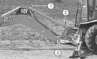
Illustration 2
g00287247
Apply lubricant to the grease fitting (1) for the head end of the boom cylinder. Apply lubricant to the grease fitting (2) for the rod end of the boom cylinder.
Apply lubricant to the grease fitting (3) for the boom pivot. There is one grease fitting on each side of the machine.
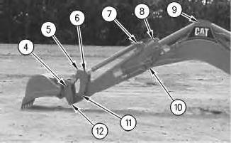
Illustration 3
g00723265
Apply lubricant to the grease fitting (9) for the head end of the stick cylinder. Apply lubricant to the grease fitting (8) for the rod end of the stick cylinder.
Apply lubricant to the grease fitting (10) for the pivot pin for the stick.
Apply lubricant to the grease fitting (7) for the head end of the bucket cylinder. Apply lubricant to the grease fitting (6) for the rod end of the bucket cylinder.
Apply lubricant to the grease fitting (11) for the pivot pin. There is one grease fitting on each side of the machine.
Apply lubricant to the grease fitting (4) for the bucket pivot pin.
Apply lubricant to the grease fitting (5) for the link.
Apply lubricant to the grease fitting (12) for the pivot pin.
There is a total of thirteen grease fittings.
Copyright 1993 - 2022 Caterpillar Inc. All Rights Reserved. Private Network For SIS Licensees. Thu Jun 30 15:59:44 UTC+0530 2022
Product: BACKHOE LOADER
Model: 424D BACKHOE LOADER RXA
Configuration: 424D Backhoe Loader RXA00001-UP (MACHINE) POWERED BY 3054C Engine
Operation and Maintenance Manual
416D, 420D, 424D, 428D, 430D, 432D and 442D Backhoe Loaders
Media Number -SEBU7821-06
Date -01/02/2015 Date Updated -26/02/2015
Backup Alarm - Test
SMCS - 7406
Turn the engine start switch key to ON in order to perform the test.
Apply the service brake. Move the transmission direction control lever to REVERSE position.
i00080741
The backup alarm should immediately sound. The backup alarm will continue to sound until the transmission direction control lever is moved to the NEUTRAL position or to the FORWARD position.
Copyright 1993 - 2022 Caterpillar Inc. All Rights Reserved. Private Network For SIS Licensees. Thu Jun 30 16:00:22 UTC+0530 2022
Product: BACKHOE LOADER
Model: 424D BACKHOE LOADER RXA
Configuration: 424D Backhoe Loader RXA00001-UP (MACHINE) POWERED BY 3054C Engine
Operation and Maintenance Manual
416D, 420D, 424D, 428D, 430D, 432D and 442D Backhoe Loaders
Battery or Battery Cable - Inspect/Replace
SMCS - 1401
1. Turn the engine start switch to the OFF position. Turn all switches to the OFF position.
2. Disconnect the negative battery cable from the frame.
Note: Do not allow the disconnected battery cable to contact the frame of the machine.
3. Disconnect the negative battery cable at the battery.
i01833495
4. Inspect the battery terminals and inspect the battery cables. Keep the terminals clean and keep the terminals coated with petroleum jelly.
5. Perform the necessary repairs. Replace the cable or the battery, as needed.
6. Connect the negative battery cable at the battery.
7. Connect the battery cable to the frame of the machine.
8. Install the engine start switch key.
Copyright 1993 - 2022 Caterpillar Inc. All Rights Reserved. Private Network For SIS Licensees. Thu Jun 30 16:00:58 UTC+0530 2022
Product: BACKHOE LOADER
Model: 424D BACKHOE LOADER RXA
Configuration: 424D Backhoe Loader RXA00001-UP (MACHINE) POWERED BY 3054C Engine
Operation and Maintenance
Manual
416D, 420D, 424D, 428D, 430D, 432D and 442D Backhoe Loaders
Belts - Inspect/Adjust/Replace
SMCS - 1357-025; 1357-040; 1357-510
If new belts are installed, check belt adjustment after 30 minutes of operation. For multiple belt drive applications, always replace the belts in matched sets. Replacing only one belt of a matched set will cause the new belt to carry more load because the older belts are stretched. The additional load on the new belt could cause the new belt to break.
1. Empty the bucket. Remove the pin that secures the brace for the loader lift arm to the left loader lift arm. Raise the loader arm to the maximum height.
2. Position the brace for the loader lift arm over the left lift cylinder rod with the flat end against the cylinder end.
3. Push the pin through the holes of the brace for the loader lift arm and install the cotter pin.
4. Slowly lower the loader arms until the brace for the loader lift arm contacts the top of the lift cylinder and the bosses on the loader arm.
5. Stop the engine in order to inspect the belts.
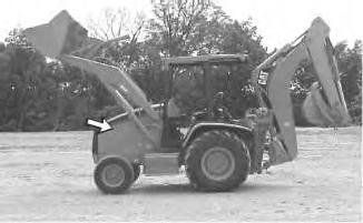
Illustration 1
6. Remove the engine access panel on the left side of the machine.
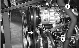
Illustration 2
7. Inspect the condition of the air conditioner belt and the adjustment of the air conditioner belt. The air conditioner belt should deflect 10 mm (0.38 inch) under 110 N (25 lb) of force.
8. Loosen the adjusting locknut (1). Loosen the compressor bracket mounting bolt (2) .
9. Move the compressor until the correct belt tension is reached.
10. Tighten the adjusting locknut (1). Tighten the compressor bracket mounting bolt (2) .
11. Recheck the belt deflection. If the amount of deflection is incorrect, repeat Step 8 to Step 10.
12. Install the engine access panel.
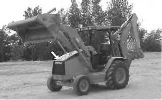
Illustration 3
13. Remove the engine access panel on the right side of the machine.
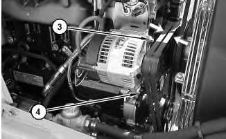
Illustration 4
14. Inspect the condition of the alternator belts and the adjustment of the alternator belts. The alternator belts should deflect 10 mm (0.38 inch) under 110 N (25 lb) of force.
15. Loosen the mounting bolt (3). Loosen the adjusting locknut (4) .
16. Move the alternator until the correct tension is reached.
17. Tighten the adjusting locknut (4). Tighten the mounting bolt (3) .
18. Recheck the belt deflection. If the amount of deflection is incorrect, repeat Step 15 to Step 17.
19. Install the engine access panel.
20. Start the engine. Raise the loader arms to the maximum height.
21. Remove the pin and replace the brace for the loader lift arm to the stored position on the loader lift arm.
22. Lower the bucket to the ground.
Copyright 1993 - 2022 Caterpillar Inc. All Rights Reserved. Private Network For SIS Licensees. Thu Jun 30 16:01:41 UTC+0530 2022
Product: BACKHOE LOADER
Model: 424D BACKHOE LOADER RXA
Configuration: 424D Backhoe Loader RXA00001-UP (MACHINE) POWERED BY 3054C Engine
Operation and Maintenance Manual
416D, 420D, 424D, 428D, 430D, 432D and 442D Backhoe Loaders Media Number -SEBU7821-06
Brake Reservoir Oil Level - Check
SMCS - 4291-535
Open the engine access door on the top of the machine.
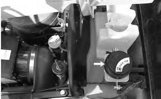
Illustration 1
i01991706
g01031571
Maintain the oil level between the "MIN" mark and "MAX" mark on the brake reservoir. Add oil, if necessary.
Copyright 1993 - 2022 Caterpillar Inc.
All Rights Reserved. Private Network For SIS Licensees. Thu Jun 30 16:02:22 UTC+0530 2022
Product: BACKHOE LOADER
Model: 424D BACKHOE LOADER RXA
Configuration: 424D Backhoe Loader RXA00001-UP (MACHINE) POWERED BY 3054C Engine
Operation and Maintenance Manual
416D, 420D, 424D, 428D, 430D, 432D and 442D Backhoe Loaders
Braking System - Test
SMCS - 4251; 4267; 7000
Service Brake Holding Ability Test
i02291147
Check the area around the machine. Make sure that the machine is clear of personnel and clear of obstacles.
Test the brakes on a dry, level surface.
Fasten the seat belt before you test the brakes.
The following tests are used to determine if the service brake is functional. These tests are not intended to measure the maximum brake holding effort. The brake holding effort that is required to sustain a machine at a specific engine rpm varies depending on the machine. The variations are the differences in the engine setting, in the power train efficiency, and in the brake holding ability, etc.
1. Start the engine. Raise the bucket slightly.
2. Apply the service brake. Release the parking brake.
3. If the machine is equipped with the standard transmission, move the transmission speed shift lever to THIRD gear. Move the transmission direction control lever to FORWARD, to NEUTRAL, and back to FORWARD. If the machine is equipped with a power shift transmission move the transmission control lever to FOURTH SPEED FORWARD, to NEUTRAL, and back to FOURTH SPEED FORWARD. This is done in order to override the transmission neutralizer for this test.
Note: Place machines that are equipped with all wheel drive into two-wheel drive mode.
4. Gradually increase the engine speed to high idle. The machine should not move.
If the machine begins to move, reduce the engine speed immediately and engage the parking brake.
5. Reduce the engine speed to low idle. Move the transmission to NEUTRAL. Engage the parking brake. Lower the bucket to the ground. Stop the engine.
NOTICE
If the machine moved while testing the brakes, contact your Caterpillar dealer. Have the dealer inspect and, if necessary, repair the service brake before returning the machine to operation.
Secondary Brake Holding Ability Test
Check the area around the machine. Make sure that the machine is clear of personnel and clear of obstacles.
Test the brakes on a dry, level surface.
Fasten the seat belt before you test the brakes.
The following tests are used to determine if the parking brake is functional. These tests are not intended to measure the maximum brake holding effort. The brake holding effort that is required to sustain a machine at a specific engine rpm varies depending on the machine. The variations are the differences in the engine setting, in the power train efficiency, and in the brake holding ability, etc.
1. Start the engine. Raise the bucket slightly.
2. Engage the parking brake.
3. If the machine is equipped with the standard transmission, move the transmission speed shift lever to THIRD gear. Move the transmission direction control lever to FORWARD, to NEUTRAL, and back to FORWARD. If the machine is equipped with a power shift transmission move the transmission control lever to FOURTH SPEED FORWARD, to NEUTRAL, and back to FOURTH SPEED FORWARD. This is done in order to override the transmission neutralizer for this test.
Note: Place machines that are equipped with all wheel drive into two-wheel drive mode.
Note: The parking brake indicator light should come on and the parking brake alarm should sound.
4. Gradually increase the engine speed to high idle. The machine should not move.
If the machine begins to move, reduce the engine speed immediately and apply the service brake pedal.
5. Reduce the engine speed. Move the transmission to NEUTRAL. Lower the bucket to the ground. Stop the engine.
NOTICE
If the machine moved while testing the brakes, contact your Caterpillar dealer.
Have the dealer inspect and, if necessary, repair the parking brakes before returning the machine to operation.
Product: BACKHOE LOADER
Model: 424D BACKHOE LOADER RXA
Configuration: 424D Backhoe Loader RXA00001-UP (MACHINE) POWERED BY 3054C Engine
Operation and Maintenance Manual
416D, 420D, 424D, 428D, 430D, 432D and 442D Backhoe Loaders
Bucket Cutting Edges - Inspect/Replace
SMCS - 6801
i01920076
Personal injury or death can result from bucket falling.
Block the bucket before changing bucket cutting edges.
1. Raise the bucket. Place a block under the bucket.
2. Lower the bucket to the blocking.
Do not block up the bucket too high. Block up the bucket so that the bucket is high enough to remove the cutting edges and the end bits.
3. Remove the bolts. Remove the cutting edge and the end bits.
4. Clean the contact surfaces.
5. Use the opposite side of the cutting edge, if this side is not worn.
6. Install a new cutting edge, if both edges are worn.
7. Install the bolts. Tighten the bolts to the specified torque.
8. Raise the bucket. Remove the blocks.
9. Lower the bucket to the ground.
10. After a few hours of operation, check the bolts for proper torque.
Copyright 1993 - 2022 Caterpillar Inc. All Rights Reserved. Private Network For SIS Licensees.
Thu Jun 30 16:04:06 UTC+0530 2022
Product: BACKHOE LOADER
Model: 424D BACKHOE LOADER RXA
Configuration: 424D Backhoe Loader RXA00001-UP (MACHINE) POWERED BY 3054C Engine
Operation and Maintenance Manual
416D, 420D, 424D, 428D, 430D, 432D and 442D Backhoe Loaders Media Number -SEBU7821-06
Bucket Tips - Inspect/Replace
SMCS - 6805
Personal injury or death can result from the bucket falling. Block the bucket before changing bucket tips.
Bucket Tips
i03657242


Illustration 1 g00101352
(1) Usable
(2) Replace the tip.
(3) Replace the tip.
Check the bucket tips for wear. If the bucket tip has a hole, replace the bucket tip.
1. Remove the pin from the bucket tip. The pin can be removed by one of the following methods.
Use a hammer and a punch from the retainer side of the bucket to drive out the pin.
Use a Pin-Master. Follow Step 1.a through Step 1.c for the procedure.
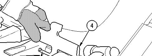

Illustration 2 g00590670 (4) Back of Pin-Master (5) Extractor
a. Place the Pin-Master on the bucket tooth.
b. Align extractor (5) with the pin.
c. Strike the Pin-Master at the back of the tool (4) and remove the pin.
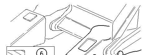
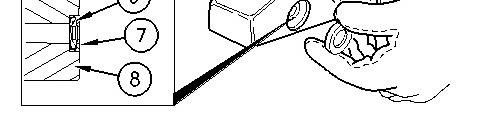
Illustration 3 g00590819 (6) Retainer (7) Retaining washer (8) Adapter
2. Clean the adapter and the pin.
3. Fit retainer (6) into retaining washer (7). Install this assembly into the groove that is in the side of adapter (8).
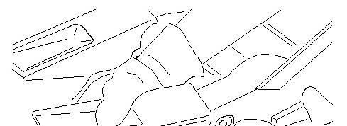

Illustration 4 g00101359
4. Install the new bucket tip onto the adapter.
Note: The bucket tip can be rotated by 180 degrees in order to allow greater penetration or less penetration.
5. Drive the pin through the bucket tip. The pin can be installed by using one of the following methods:
From the other side of the retainer, drive the pin through the bucket tip, the adapter, and the retainer.
Use a Pin-Master. Follow Step 5.a through Step 5.e for the procedure.
Note: To correctly install the pin into the retainer, the pin must be driven in from the right side of the tooth. Improper installation of the pin can result in the loss of the bucket tip.
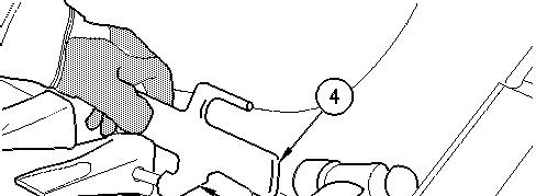

Illustration 5 g00590666 (4) Back of Pin-Master (9) Pin setter (10) Pin holder
a. Insert the pin through the bucket tooth.
b. Place the Pin-Master over the bucket tooth and locate the pin in the hole of holder (10).
c. Strike the tool with a hammer at the back of the tool (4) in order to start the pin.
d. Slide pin holder (10) away from the pin and rotate the tool slightly in order to align pin setter (9) with the pin.
e. Strike the end of the tool until the pin is fully inserted.
6. After you drive the pin, make sure that the retainer fits snugly into the pin groove.
This is the sample of the manual Click on the download link for complete Manual