

Product: BACKHOE LOADER
Model: 422E BACKHOE LOADER HBE
Configuration: 422E Backhoe Loader Single Tilt Side Shift Boom HBE00001-UP (MACHINE) POWERED BY 3054C Engine
Operation and Maintenance Manual 416E, 422E and 428E Backhoe Loaders
Media Number -SEBU7970-16 Publication Date -01/02/2015 Date Updated -08/04/2019
Foreword
California Proposition 65 Warning
Diesel engine exhaust and some of its constituents are known to the State of California to cause cancer, birth defects, and other reproductive harm.

WARNING - This product can expose you to chemicals including ethylene glycol, which is known to the State of California to cause birth defects or other reproductive harm. For more information go to:
www.P65Warnings.ca.gov
Do not ingest this chemical. Wash hands after handling to avoid incidental ingestion.
WARNING - This product can expose you to chemicals including lead and lead compounds, which are known to the State of California to cause cancer, birth defects, or other reproductive harm. For more information go to:
www.P65Warnings.ca.gov
Wash hands after handling components that may contain lead.
Literature Information
This manual should be stored in the operator's compartment in the literature holder or seat back literature storage area.
This manual contains safety information, operation instructions, transportation information, lubrication information, and maintenance information.
Some photographs or illustrations in this publication show details or attachments that can be different from your machine. Guards and covers might have been removed for illustrative purposes.
Continuing improvement and advancement of product design might have caused changes to your machine which are not included in this publication. Read, study, and keep this manual with the machine.
Whenever a question arises regarding your machine, or this publication, please consult your Cat dealer for the latest available information.
Safety
The safety section lists basic safety precautions. In addition, this section identifies the text and locations of warning signs and labels used on the machine.
Read and understand the basic precautions listed in the safety section before operating or performing lubrication, maintenance, and repair on this machine.
Operation
The operation section is a reference for the new operator and a refresher for the experienced operator. This section includes a discussion of gauges, switches, machine controls, attachment controls, transportation, and towing information.
Photographs and illustrations guide the operator through correct procedures of checking, starting, operating, and stopping the machine.
Operating techniques outlined in this publication are basic. Skill and techniques develop as the operator gains knowledge of the machine and its capabilities.
Maintenance
The maintenance section is a guide to equipment care. The Maintenance Interval Schedule (MIS) lists the items to be maintained at a specific service interval. Items without specific intervals are listed under the "When Required" service interval. The Maintenance Interval Schedule lists the page number for the step-by-step instructions required to accomplish the scheduled maintenance. Use the Maintenance Interval Schedule as an index or "one safe source" for all maintenance procedures.
Maintenance Intervals
Use the service hour meter to determine servicing intervals. Calendar intervals shown (daily, weekly, monthly, etc.) can be used instead of service hour meter intervals if the calendar intervals
provide more convenient servicing schedules and approximate the indicated service hour meter reading. Perform the recommended service at the interval that occurs first.
Under severe, dusty, or wet operating conditions, more frequent lubrication than is specified in the maintenance intervals chart might be necessary.
Perform service on items at multiples of the original requirement. For example, at every 500 service hours or 3 months, also service those items listed under every 250 service hours or monthly and every 10 service hours or daily.
Certified Engine Maintenance
Proper maintenance and repair are essential to keep the engine and machine systems operating correctly. As the heavy-duty off-road diesel engine owner, you are responsible for the performance of the required maintenance listed in the Owner Manual, Operation and Maintenance Manual, and Service Manual.
It is prohibited for any person engaged in the business of repairing, servicing, selling, leasing, or trading engines or machines to remove, alter, or to render inoperative, any emission-related device or element of design installed on or in an engine or machine that is in compliance with all applicable regulations of the intended country to which it has been shipped. Certain elements of the machine and engine such as the exhaust system, fuel system, electrical system, intake air system, and cooling system may be emission-related and should not be altered unless approved by Caterpillar.
Machine Capacity
Additional attachments or modifications may exceed machine design capacity which can adversely affect performance characteristics. Included would be stability and system certifications such as brakes, steering, and rollover protective structures (ROPS). Contact your Cat dealer for further information.
Product Identification Number
Effective First Quarter 2001 the Product Identification Number (PIN) has changed from 8 to 17 characters. To provide uniform equipment identification, construction equipment manufacturers are moving to comply with the latest version of the product identification numbering standard. Non-road machine PINs are defined by ISO 10261. The new PIN format will apply to all machines and generator sets. The PIN plates and frame marking will display the 17 character PIN. The new format will look like the following:
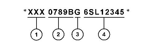
Illustration 1 g03891925
Where:
1. World Manufacturing Code (characters 1-3)
2. Machine Descriptor (characters 4-8)
3. Check Character (character 9)
4. Machine Indicator Section (MIS) or Product Sequence Number (characters 10-17). These were previously referred to as the Serial Number.
Machines and generator sets produced before First Quarter 2001 will maintain their 8 character PIN format.
Components such as engines, transmissions, axles, and work tools will continue to use an 8 character Serial Number (S/N).
Copyright 1993 - 2023 Caterpillar Inc. All Rights Reserved.
Private Network For SIS Licensees. Tue Mar 7 16:23:01 UTC+0530 2023
This is the sample of the manual Click on the download link for complete Manual

Product: BACKHOE LOADER
Model: 422E BACKHOE LOADER HBE
Configuration: 422E Backhoe Loader Single Tilt Side Shift Boom HBE00001-UP (MACHINE) POWERED BY 3054C Engine
Operation and Maintenance Manual
416E, 422E and 428E Backhoe Loaders
Media Number -SEBU7970-16
Publication Date -01/02/2015 Date Updated -08/04/2019
Axle Breathers - Clean/Replace
SMCS - 3278-070-BRE; 3278-510-BRE
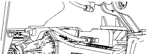
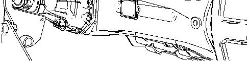
Illustration 1 g01216797
The front axle breather is located on the top right side of the differential housing.
i02436158
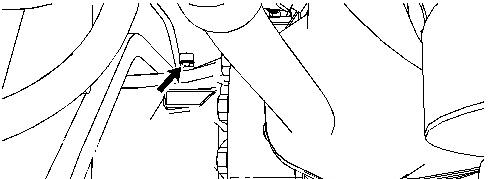
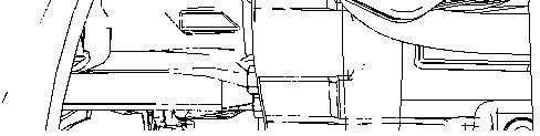
Illustration 2 g01216798
The rear axle breather is located to the left of the differential housing.
1. Clean the area around the breathers. Remove the breather from the front axle.
2. Wash the breather in clean nonflammable solvent. Wipe the breather dry and check the breather for damage.
3. Install the clean breather back into the axle. Replace the breather if the breather is damaged.
Note: Make sure that the slot in the breather is parallel to the axle housing.
1993 - 2023 Caterpillar Inc.
Product: BACKHOE LOADER
Model: 422E BACKHOE LOADER HBE
Configuration: 422E Backhoe Loader Single Tilt Side Shift Boom HBE00001-UP (MACHINE) POWERED BY 3054C Engine
Operation and Maintenance Manual
416E, 422E and 428E Backhoe Loaders
Media Number -SEBU7970-16 Publication Date -01/02/2015 Date Updated -08/04/2019
Backhoe Boom, Stick, Bucket, and Cylinder BearingsLubricate
SMCS - 6501-086-BD; 6502-086-BD; 6503-086-BD; 6511-086-BD; 6512-086-BD; 6533-086BD; 7562-086-BD
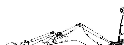
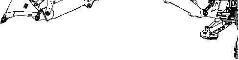
Illustration 1 g01194613
Position the backhoe into the service position that is shown above. Lower the bucket to the ground. Relieve the hydraulic pressure.
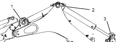

2 g01194615
Apply lubricant to the grease fitting (1) for the rod end of the stick cylinder.
Apply lubricant to the grease fitting (2) for the head end of the boom cylinder and the head end of the stick cylinder.
Apply lubricant to the grease fitting (3) for the rod end of the boom cylinder.
Apply lubricant to the grease fitting (4) for the boom pivot. There is one grease fitting on each side of the machine.
3 g01194617
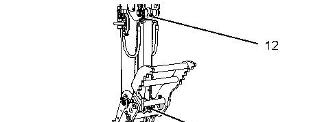
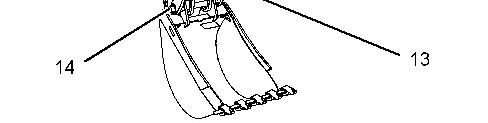
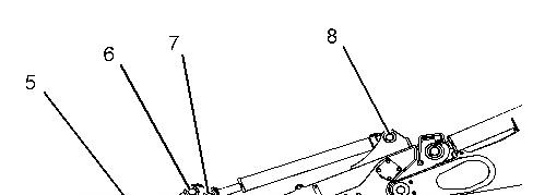
Illustration 4 g01491621
Apply lubricant to the grease fitting (5) for the bucket pivot pin.
Apply lubricant to the grease fitting (6) for the link.
Apply lubricant to the grease fitting (7) for the rod end of the bucket cylinder.
Apply lubricant to the grease fitting (8) for the head end of the bucket cylinder.
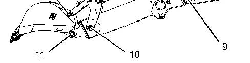
Apply lubricant to the grease fitting (9) for the pivot pin for the stick.
Apply lubricant to the grease fitting (10) for the pivot pin. There is one grease fitting on each side of the machine.
Apply lubricant to the grease fitting (11) for the pivot pin.
Apply lubricant to the grease fitting (12) for the head end of the thumb cylinder.
Apply lubricant to the grease fitting (13) for the rod end of the thumb cylinder.
Apply lubricant to the grease fitting (14) for the pivot pin on each side of the thumb.
There is a total of 21 grease fittings. Copyright 1993 - 2023 Caterpillar Inc.
Product: BACKHOE LOADER
Model: 422E BACKHOE LOADER HBE
Configuration: 422E Backhoe Loader Single Tilt Side Shift Boom HBE00001-UP (MACHINE) POWERED BY 3054C Engine
Operation and Maintenance Manual
416E, 422E and 428E Backhoe Loaders
Media Number -SEBU7970-16
Publication Date -01/02/2015 Date Updated -08/04/2019
Backup Alarm - Test
SMCS - 7406
Turn the engine start switch key to ON in order to perform the test.
Apply the service brake. Move the transmission direction control lever to REVERSE position.
The backup alarm should immediately sound. The backup alarm will continue to sound until the transmission direction control lever is moved to the NEUTRAL position or to the FORWARD position.
Copyright 1993 - 2023 Caterpillar Inc. All Rights Reserved. Private Network For SIS Licensees.
Tue Mar 7 16:28:08 UTC+0530 2023
Product: BACKHOE LOADER
Model: 422E BACKHOE LOADER HBE
Configuration: 422E Backhoe Loader Single Tilt Side Shift Boom HBE00001-UP (MACHINE) POWERED BY 3054C Engine
Operation and Maintenance Manual
416E, 422E and 428E Backhoe Loaders
Media Number -SEBU7970-16
Publication Date -01/02/2015 Date Updated -08/04/2019
Battery - Recycle
SMCS - 1401-561
Always recycle a battery. Never discard a battery.
Always return used batteries to one of the following locations:
• A battery supplier
• An authorized battery collection facility
• Recycling facility
Copyright 1993 - 2023 Caterpillar Inc. All Rights Reserved. Private Network For SIS Licensees.
i07746330
Tue Mar 7 16:28:25 UTC+0530 2023
Product: BACKHOE LOADER
Model: 422E BACKHOE LOADER HBE
Configuration: 422E Backhoe Loader Single Tilt Side Shift Boom HBE00001-UP (MACHINE) POWERED BY 3054C Engine
Operation and Maintenance Manual
416E, 422E and 428E Backhoe Loaders
Media Number -SEBU7970-16 Publication Date -01/02/2015 Date Updated -08/04/2019
Battery or Battery Cable - Inspect/Replace
SMCS - 1401
i01833495
1. Turn the engine start switch to the OFF position. Turn all switches to the OFF position.
2. Disconnect the negative battery cable from the frame.
Note: Do not allow the disconnected battery cable to contact the frame of the machine.
3. Disconnect the negative battery cable at the battery.
4. Inspect the battery terminals and inspect the battery cables. Keep the terminals clean and keep the terminals coated with petroleum jelly.
5. Perform the necessary repairs. Replace the cable or the battery, as needed.
6. Connect the negative battery cable at the battery.
7. Connect the battery cable to the frame of the machine.
8. Install the engine start switch key.
Copyright 1993 - 2023 Caterpillar Inc. All Rights Reserved. Private Network For SIS Licensees. Tue Mar 7 16:28:39 UTC+0530 2023
Product: BACKHOE LOADER
Model: 422E BACKHOE LOADER HBE
Configuration: 422E Backhoe Loader Single Tilt Side Shift Boom HBE00001-UP (MACHINE) POWERED BY 3054C Engine
Operation and Maintenance Manual
416E, 422E and 428E Backhoe Loaders
Media Number -SEBU7970-16 Publication Date -01/02/2015 Date Updated -08/04/2019
Belts - Inspect/Adjust/Replace
SMCS - 1357-040; 1357-510; 1357-025
If new belts are installed, check belt adjustment after 30 minutes of operation. For multiple belt drive applications, always replace the belts in matched sets. Replacing only one belt of a matched set will cause the new belt to carry more load because the older belts are stretched. The additional load on the new belt could cause the new belt to break.
1. Install the lift cylinder brace. Refer to Operation and Maintenance Manual, "Lift Cylinder Brace - Connect and Disconnect" for more information.
2. Remove the engine access panel on the left side of the machine.
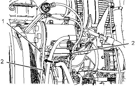
3. Inspect the condition of the air conditioner belt and the adjustment of the air conditioner belt. The air conditioner belt should deflect 10 mm (0.38 inch) under 110 N (25 lb) of force.
4. Loosen the adjusting locknut (1) . Loosen the two compressor bracket mounting bolts (2) .
5. Move the compressor until the correct belt tension is reached.
6. Tighten the adjusting locknut (1) . Tighten the two compressor bracket mounting bolts (2) .
7. Recheck the belt deflection. If the amount of deflection is incorrect, repeat Step 4 to Step 6.
8. Install the engine access panel.
9. Remove the engine access panel on the right side of the machine.
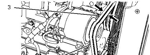
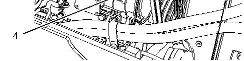
Illustration 2
g01178833
10. Inspect the condition of the alternator belts and the adjustment of the alternator belts. The alternator belts should deflect 10 mm (0.38 inch) under 110 N (25 lb) of force.
11. Loosen the mounting bolt (3) . Loosen the adjusting locknut (4) .
12. Move the alternator until the correct tension is reached.
13. Tighten the adjusting locknut (4) . Tighten the mounting bolt (3) .
14. Recheck the belt deflection. If the amount of deflection is incorrect, repeat Step 11 to Step 13.
15. Install the engine access panel.
16. Start the engine. Raise the loader arms to the maximum height.
17. Remove the pin and replace the brace for the loader lift arm to the stored position on the loader lift arm.
18. Lower the bucket to the ground.
Copyright 1993 - 2023 Caterpillar Inc. All Rights Reserved. Private Network For SIS Licensees.
Tue Mar 7 16:28:57 UTC+0530 2023
Product: BACKHOE LOADER
Model: 422E BACKHOE LOADER HBE
Configuration: 422E Backhoe Loader Single Tilt Side Shift Boom HBE00001-UP (MACHINE) POWERED BY 3054C Engine
Operation and Maintenance Manual
416E, 422E and 428E Backhoe Loaders
Media Number -SEBU7970-16
Publication Date -01/02/2015 Date Updated -08/04/2019
Brake Reservoir Oil Level - Check
SMCS - 4291-535
Open the engine access door on the top of the machine.
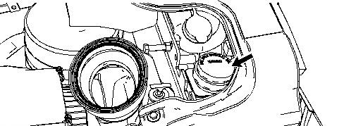
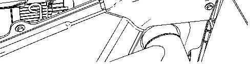
Illustration 1 g01203566
The use of a pressure washer on the engine compartment can force water into the brake reservoir. Water that enters the brake reservoir
can result in a reduced braking ability. A reduced braking ability could result in personal injury or death. Do not use a pressure washer to wash the brake reservoir.
Maintain the oil level between the "MIN" mark and "MAX" mark on the brake reservoir. Add oil, if necessary.
Note: Ensure that the filler cap is clean before removing the cap from the reservoir.
Note: Do not clean the area near the brake reservoir with high pressure water. If water entered the reservoir contact your local Caterpillar dealer.
Copyright 1993 - 2023 Caterpillar Inc. All Rights Reserved. Private Network For SIS Licensees. Tue Mar 7 16:29:12 UTC+0530 2023
Product: BACKHOE LOADER
Model: 422E BACKHOE LOADER HBE
Configuration: 422E Backhoe Loader Single Tilt Side Shift Boom HBE00001-UP (MACHINE) POWERED BY 3054C Engine
Operation and Maintenance Manual
416E, 422E and 428E Backhoe Loaders
Media Number -SEBU7970-16
Braking System - Test
SMCS - 4251; 4267; 7000
S/N - HBE1-UP
S/N - SNL1-UP
Date -01/02/2015 Date Updated -08/04/2019
Service Brake Holding Ability Test
Check the area around the machine. Make sure that the machine is clear of personnel and clear of obstacles.
Test the brakes on a dry, level surface.
Fasten the seat belt before you test the brakes.
The following tests are used to determine if the service brake is functional. These tests are not intended to measure the maximum brake holding effort. The brake holding effort that is required to sustain a machine at a specific engine rpm varies depending on the machine. The variations are the differences in the engine setting, in the power train efficiency, and in the brake holding ability, etc.
1. Start the engine. Raise the bucket slightly.
2. Apply the service brake. Release the parking brake.
3. Move the transmission control lever to THIRD SPEED FORWARD.
4. Gradually increase the engine speed to high idle. The machine should not move.
If the machine begins to move, reduce the engine speed immediately and engage the parking brake.
5. Reduce the engine speed to low idle. Move the transmission to NEUTRAL. Engage the parking brake. Lower the bucket to the ground. Stop the engine.
NOTICE
If the machine moved while testing the brakes, contact your Caterpillar dealer. Have the dealer inspect and, if necessary, repair the service brake before returning the machine to operation.
Secondary Brake Holding Ability Test
Check the area around the machine. Make sure that the machine is clear of personnel and clear of obstacles.
Test the brakes on a dry, level surface.
Fasten the seat belt before you test the brakes.
The following tests are used to determine if the parking brake is functional. These tests are not intended to measure the maximum brake holding effort. The brake holding effort that is required to sustain a machine at a specific engine rpm varies depending on the machine. The variations are the differences in the engine setting, in the power train efficiency, and in the brake holding ability, etc.
1. Start the engine. Raise the bucket slightly.
2. Engage the parking brake.
3. Move the transmission control lever to THIRD SPEED FORWARD, then to NEUTRAL, then back to THIRD SPEED FORWARD.
Note: The parking brake indicator light should come on and the parking brake alarm should sound.
4. Gradually increase the engine speed to high idle. The machine should not move.
If the machine begins to move, reduce the engine speed immediately and apply the service brake pedal.
5. Reduce the engine speed. Move the transmission to NEUTRAL. Lower the bucket to the ground. Stop the engine.
NOTICE
If the machine moved while testing the brakes, contact your Caterpillar dealer.
Have the dealer inspect and, if necessary, repair the parking brakes before returning the machine to operation.
1993 - 2023 Caterpillar Inc.
Rights Reserved.
Network For SIS Licensees. Tue Mar 7 16:29:32 UTC+0530 2023
Product: BACKHOE LOADER
Model: 422E BACKHOE LOADER HBE
Configuration: 422E Backhoe Loader Single Tilt Side Shift Boom HBE00001-UP (MACHINE) POWERED BY 3054C Engine
Operation and Maintenance Manual
416E, 422E and 428E Backhoe Loaders
Media Number -SEBU7970-16 Publication Date -01/02/2015 Date Updated -08/04/2019
Bucket Cutting Edges - Inspect/Replace
SMCS - 6801
Personal injury or death can result from bucket falling. Block the bucket before changing bucket cutting edges.
1. Raise the bucket. Place a block under the bucket.
2. Lower the bucket to the blocking.
Do not block up the bucket too high. Block up the bucket so that the bucket is high enough to remove the cutting edges and the end bits.
3. Remove the bolts. Remove the cutting edge and the end bits.
4. Clean the contact surfaces.
5. Use the opposite side of the cutting edge, if this side is not worn.
6. Install a new cutting edge, if both edges are worn.
7. Install the bolts. Tighten the bolts to the specified torque.
8. Raise the bucket. Remove the blocks.
9. Lower the bucket to the ground.
10. After a few hours of operation, check the bolts for proper torque.
Product: BACKHOE LOADER
Model: 422E BACKHOE LOADER HBE
Configuration: 422E Backhoe Loader Single Tilt Side Shift Boom HBE00001-UP (MACHINE) POWERED BY 3054C Engine
Operation and Maintenance Manual
416E, 422E and 428E Backhoe Loaders
Media Number -SEBU7970-16
Publication Date -01/02/2015 Date Updated -08/04/2019
Bucket Tips - Inspect/Replace
SMCS - 6805
Personal injury or death can result from the bucket falling.
Block the bucket before changing bucket tips.


Illustration 1 g00101352
(1) This tip is usable. (2) This tip should be replaced. (3) This tip has been overworn.
Check the bucket tips for wear. If the bucket tip has a hole, replace the bucket tip.
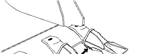
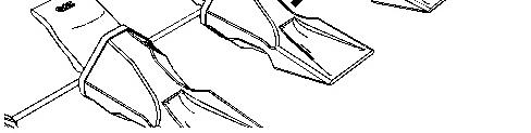
Illustration 2 g01272671
1. Drive the pin out of the bucket tip from the retainer side of the bucket tip. Remove the bucket tip and the retainer.

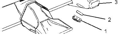
Illustration 3 g01272854
(1) Retaining washer (2) Retainer (3) Adapter
2. Clean the adapter and the pin.
3. Fit retainer (2) into retaining washer (1). Install this assembly into the groove that is in the side of adapter (3).
This is the sample of the manual Click on the download link for complete Manual