

Product: MULTI TERRAIN LOADER
Model: 297D MULTI TERRAIN LOADER BE7
Configuration: 297D/297D XHP Multi Terrain Loader BE700001-UP (MACHINE) POWERED BY C3.8 Engine
Disassembly and Assembly
C3.8 Engines for Caterpillar Built Machines Media Number -UENR0129-08
i04770500
Air Inlet Heater - Remove and Install
SMCS - 1090-010
Removal Procedure
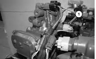
Illustration 1
1. Disconnect harnessassemblies(1).
g02870556
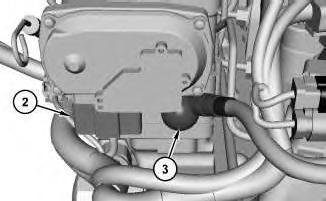
Illustration 2
g02870616
2. Disconnect harnessassembly (2) and cable assembly (3).
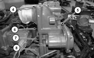
Illustration 3
g02870576
3. Remove bolts (4) and bolts(5). Remove flange (6), valve assembly (7), air inlet heater (8), and the gaskets.
Installation Procedure
1. Install newgaskets, air inlet heater (8), valve assembly (7), and flange (6) in the reverse order of removal.
a. Tighten the nut for cable assembly (3) to a torque of 4.4 ± 0.9 N·m (38.9 ±8.0 lb in).
Copyright 1993 - 2020 Caterpillar Inc. All Rights Reserved. Private Network For SIS Licensees. Tue Jun 16 15:32:51 UTC+0530 2020
Product: MULTI TERRAIN LOADER
Model: 297D MULTI TERRAIN LOADER BE7
Configuration: 297D/297D XHP Multi Terrain Loader BE700001-UP (MACHINE) POWERED BY C3.8 Engine
Disassembly and Assembly
C3.8 Engines for Caterpillar Built Machines
i06621882
Alternator - Remove and Install
SMCS - 1405-010
Removal Procedure
1. Refer to Operation and Maintenance Manual, "Radiator Tilting".
2. Refer to Operation and Maintenance Manual, "Belts - Inspect/Adjust/Replace".
3. Refer to Operation and Maintenance Manual, "Battery or Battery Cable - Inspect/Replace".
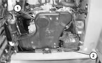
Illustration 1 g06050364 SSL, MTL, andCTLmodels.
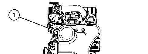
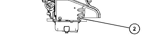
Illustration 2 g06050387 CWLmodels.
4. For SSL, MTL, and CTL models refer to illustration 1. Loosen quarter turn fasteners (2) and remove guard (1).
For the CWL models, refer to illustration 2. Remove bolts(2) and guard (1).
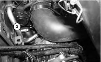
Illustration 3 g06050407
5. For the SSL, MTL, and CTL models, remove hose (3). For the CWL (910K/914K) go to Step 6.
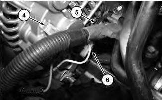
Illustration 4
g06050414
6. Disconnect wire assembly (4), cable assembly (5), and wire assembly (6).
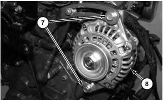
Illustration 5
7. Remove bolts (7). Remove alternator (8).
Installation Procedure
g06050420
1. Install alternator (8) in the reverse order of removal.
a. Tighten bolts (7) to a torque of 69 N·m ± 10 N·m (51 ± 7 lb ft).
Copyright 1993 - 2020 Caterpillar Inc. All Rights Reserved. Private Network For SIS Licensees. Tue Jun 16 15:47:31 UTC+0530 2020
Product: MULTI TERRAIN LOADER
Model: 297D MULTI TERRAIN LOADER BE7
Configuration: 297D/297D XHP Multi Terrain Loader BE700001-UP (MACHINE) POWERED BY C3.8 Engine
Disassembly and Assembly
C3.8 Engines for Caterpillar Built Machines Media Number -UENR0129-08
i06621308
Boost Pressure Sensor - Remove and Install
SMCS - 1917-010
Removal Procedure
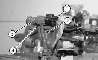
Illustration 1
g02893620
1. Disconnect harnessassembly (1). Remove hose (2). Remove bolts(3) to remove boost pressure sensor (4).
Installation Procedure
1. Install boost pressure sensor (4) in the reverse order of removal.
a. Tighten bolts (3) to a torque of 4 N·m to 5 N·m (35 ±44 lb in).
Tue Jun 16 15:46:54 UTC+0530 2020
This is the sample of the manual
Click on the download link for complete Manual
Product: MULTI TERRAIN LOADER
Model: 297D MULTI TERRAIN LOADER BE7
Configuration: 297D/297D XHP Multi Terrain Loader BE700001-UP (MACHINE) POWERED BY C3.8 Engine
Disassembly and Assembly
C3.8 Engines for Caterpillar Built Machines
i04663730
Camshaft - Remove and Install
SMCS - 1210-010
Removal Procedure
Start By:
a. Remove the front housing.
b. Remove the rocker shaft and pushrods.
1. Refer to SystemsOperation, Testing and Adjusting, "Finding Top Center Position for No.4 Piston".
1
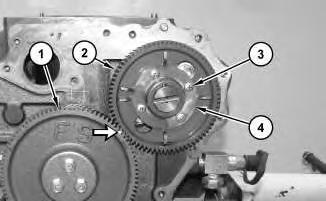
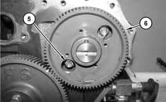
2. Mark the alignment of gear (1) and gear (2) for installation purposes.
3. Remove bolts (3) and pulsar gear (4).
2
g02863959
4. Remove bolts (5). Remove camshaft assembly (6).
Installation Procedure
1. Lubricate the camshaft assembly with clean engine oil prior to installation.
2. Ensure that the camshaft assembly isclean and free from wear or damage.
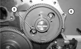
Illustration 3
g02863959
NOTICE
Do not damage the lobesor the bearingswhen the camshaft is removed or installed.
3. Install camshaft assembly (6). Install bolts (5). Tighten bolts(5) to a torque of 25.5 ± 1.5 N·m (18.8 ± 1.1 lb ft).
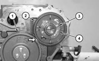
Illustration 4 g02864436
4. Install pulsar gear (4) and screws(3). Tighten screws (3) to a torque of 5.2 ±0.5 N·m (45.6 ± 4.0 lb in)Ensure that gear (1) and gear (2) are aligned.
5. Lubricate the teeth of the gearswith clean engine oil.
6. Refer to Specifications, "Camshaft" for more information.
End By:
a. Install the front housing.
b. Install the rocker shaft and pushrods.
Product: MULTI TERRAIN LOADER
Model: 297D MULTI TERRAIN LOADER BE7
Configuration: 297D/297D XHP Multi Terrain Loader BE700001-UP (MACHINE) POWERED BY C3.8 Engine
Disassembly and Assembly
C3.8 Engines for Caterpillar Built Machines
Media Number -UENR0129-08 Publication Date -01/09/2015 Date Updated -19/05/2016
i04663712
Camshaft Gear - Remove and Install
SMCS - 1210-010-GE
Removal Procedure
Start By:
a. Remove the camshaft assembly from the engine.
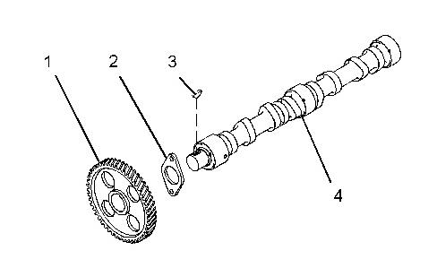
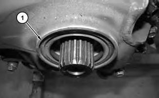
Illustration 1 g01350917
1. Place the camshaft assembly on a suitable support. Use a pressto remove camshaft gear (1) from camshaft (4).
2. Remove thrust plate (2) and woodruff key (3) from camshaft (4). Note the orientation of the thrust plate for installation.
Installation Procedure
1. Ensure that all components of the camshaft assembly are clean and free from damage.
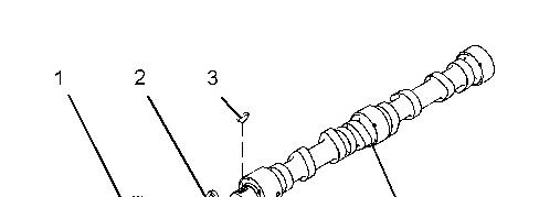

Illustration 2
2. Install woodruff key (3) and thrust plate (2) to camshaft (4).
g01350917
Note: Ensure that the machined face of the thrust plate istoward the camshaft.
Alwayswear protective gloves whenhandling partsthat have been heated.
3. Raise the temperature of camshaft gear (1). Align the camshaft gear with woodruff key (3) and install the camshaft gear to camshaft (4).
4. Refer to Specifications, "Camshaft" for more information.
End By:
a. Install the camshaft assembly to the engine. Copyright 1993 - 2020 Caterpillar Inc. All Rights Reserved. Private Network For SIS Licensees.
Tue Jun 16 15:43:00 UTC+0530 2020
Product: MULTI TERRAIN LOADER
Model: 297D MULTI TERRAIN LOADER BE7
Configuration: 297D/297D XHP Multi Terrain Loader BE700001-UP (MACHINE) POWERED BY C3.8 Engine
Disassembly and Assembly
C3.8 Engines for Caterpillar Built Machines Media Number -UENR0129-08
-19/05/2016
i04783390
Camshaft Position Sensor - Remove and Install
SMCS - 1912-010
Removal Procedure
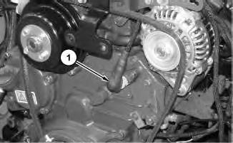
Illustration 1
1. Disconnect harnessassembly (1).
g02893160
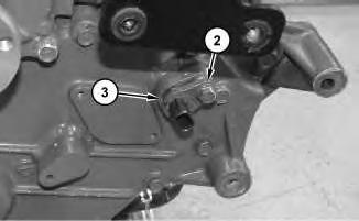
Illustration 2
2. Remove bolt (2) to remove position sensor (3) and the O-ring seal.
Installation Procedure
1. Install camshaft position sensor (3) and a new O-ring seal in the reverse order of removal.
a. Tighten bolt (2) to a torque of 4.5 ± 0.5 N·m (39.8 ± 4.4 lb in).
Copyright 1993 - 2020 Caterpillar Inc. All Rights Reserved. Private Network For SIS Licensees. Tue Jun 16 15:45:52 UTC+0530 2020
Product: MULTI TERRAIN LOADER
Model: 297D MULTI TERRAIN LOADER BE7
Configuration: 297D/297D XHP Multi Terrain Loader BE700001-UP (MACHINE) POWERED BY C3.8 Engine
Disassembly and Assembly
C3.8 Engines for Caterpillar Built Machines
Coolant Temperature Sensor - Remove and Install
SMCS - 1906-010
Removal Procedure
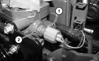
Illustration 1 g02851436
1. Disconnect harnessassembly (1) .
2. Remove coolant temperature sensor (2) .
Installation Procedure
1. Install coolant temperature sensor (2) in the reverse order of removal.
a. Tighten temperature sensor (2) to a torque of 17.5 ± 5.5 N·m (155 ± 49 lb in).
i04815979
Copyright 1993 - 2020 Caterpillar Inc.
Tue Jun 16 15:46:20 UTC+0530 2020
Product: MULTI TERRAIN LOADER
Model: 297D MULTI TERRAIN LOADER BE7
Configuration: 297D/297D XHP Multi Terrain Loader BE700001-UP (MACHINE) POWERED BY C3.8 Engine
Disassembly and Assembly
C3.8 Engines for Caterpillar Built Machines
i06620851
Crankshaft - Install
SMCS - 1202-012
Installation Procedure Table 1
- Three Bond 1217D -
1. Refer to Specifications, "Crankshaft" for more information. If necessary, replace the crankshaft or recondition the crankshaft.
2. Ensure that the parent bores for the crankshaft bearings in the cylinder block are clean. Ensure that the threads for the bearing bolts in the cylinder block are clean and free from damage.
3. Clean the crankshaft bearings and the thrust washers. Inspect the bearings and the thrust washers for wear or damage. If necessary, replace the bearingsand the thrust washers.
Note: If the crankshaft bearings are replaced, check whether oversize bearingswere previously installed. If the thrust washers are replaced, check whether oversize thrust washers were previously installed.
4. Ensure that all of the lubrication passages are clean and free of debris.
1
g02861383
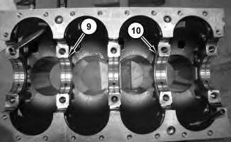
5. Install the upper thrust bearing (10) and the upper main bearings (9).
Note: The upper thrust bearing (10) is installed at the Number (4) bearing cap with the oil groove facing outward.
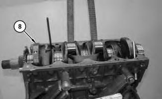
Illustration 2
g02861360
6. Use a suitable lifting device to install crankshaft (8). The weight of crankshaft (8) is approximately 32 kg (70 lb).
Note: Do not damage the finished surfaces on the crankshaft.
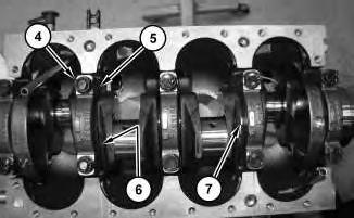
Illustration 3
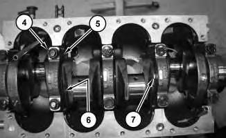
7. Apply clean engine oil onto bolts (4). Install bearing caps(5) and install bolts(4).Tighten bolts (4) to a torque of 142.5 ± 4.5 N·m (105.1 ± 3.3 lb ft).
8. Install the lower thrust bearing (7) and the lower main bearings (6).
Note: The lower thrust bearing (7) is installed at the Number (4) bearing cap with the oil groove facing outward.
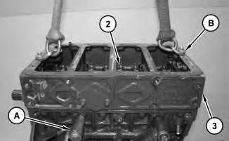
Illustration 4
9. Apply Tooling (C) onto the mating surface of crankcase (3). Use Tooling (B) and a suitable lifting device to install crankcase (3). Install bolts(2). Tighten bolts (2) to a torque of 52 ± 3 N·m (38.4 ± 2.2 lb ft).
10. Rotate engine (1) to the upright position.
11. Check the crankshaft end play, side clearance, and oil clearance. Refer to Specifications, "Crankshaft" for more information.
12. If the crankshaft has been reground or if the crankshaft has been replaced, the height of the piston above the cylinder block must be inspected to determine the correct head gasket
thickness. Refer to Specification, "Cylinder Head" and the section on Selecting the Correct Cylinder Head Gasket.
13. Remove engine (1) from Tooling (A).
End By:
a. Install the pistons and connecting rods.
b. Install the front housing.
c. Install the flywheel housing.
d. Install the oil strainer.
e. Install the cylinder head Copyright 1993 - 2020 Caterpillar Inc.
Product: MULTI TERRAIN LOADER
Model: 297D MULTI TERRAIN LOADER BE7
Configuration: 297D/297D XHP Multi Terrain Loader BE700001-UP (MACHINE) POWERED BY C3.8 Engine
Disassembly and Assembly
C3.8 Engines for Caterpillar Built Machines
Crankshaft - Remove
SMCS - 1202-011
Removal Procedure
Table 1
Start By:
a. Remove the cylinder head
b. Remove the oil strainer.
c. Remove the flywheel housing.
d. Remove the front housing.
e. Remove the pistons and connecting rods.
NOTICE
If the crankshaft hasbeenreground or if the crankshaft hasbeen replaced, the height of the piston above the cylinder block must be
i06620815
inspected to determine the correct head gasket thickness. Refer to Specification, "Cylinder Head" and the sectionon Selecting the Correct Cylinder HeadGasket.
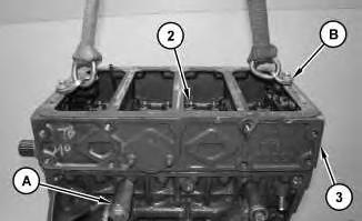
Illustration 1
g02861239
a. Install engine (1) onto Tooling (A) and rotate to the inverted position.
b. Remove bolts (2). Use Tooling (B) and a suitable lifting device to remove crankcase (3).
2
c. Remove bolts (4) to remove bearing caps(5). Remove the lower main bearings (6) and the lower thrust bearing (7).
Note: Note the location and orientation of bearing caps (5) for installation purposes.
Note: Keep the lower main bearingsand the lower thrust bearing with the respective main bearing caps
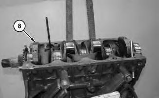
Illustration 3
g02861360
d. Use a suitable lifting device to remove crankshaft (8). The weight of crankshaft (8) is approximately 32 kg (70 lb).
Note: Do not damage the finished surfaces on the crankshaft.
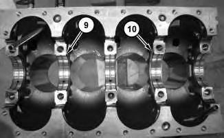
Illustration 4
g02861383
e. Remove the upper main bearings (9) and the upper thrust bearing (10). Keep the upper main bearings and the upper thrust bearing with the respective main bearing caps.
Copyright 1993 - 2020 Caterpillar Inc. All Rights Reserved. Private Network For SIS Licensees. Tue Jun 16 15:44:22 UTC+0530 2020
Product: MULTI TERRAIN LOADER
Model: 297D MULTI TERRAIN LOADER BE7
Configuration: 297D/297D XHP Multi Terrain Loader BE700001-UP (MACHINE) POWERED BY C3.8 Engine
Disassembly and Assembly
C3.8 Engines for Caterpillar Built Machines
Crankshaft Front Seal - Remove and Install
SMCS - 1160-010
Removal Procedure
Table 1 Required Tools
Start By:
a. Remove the crankshaft pulley.
NOTICE
Ensure that the mainlip is used in order to remove the crankshaft front seal. Do not damage the edge of the housing for the crankshaft front seal.
i04664010
This is the sample of the manual
Click on the download link for complete Manual
1
1. Use Tooling (A) to drill three evenly spaced holes in crankshaft front seal (1).
2. Use Tooling (B) to carefully remove crankshaft front seal (1). Alternate the position of Tooling (B) from one hole to another hole to allow the crankshaft front seal to be removed.
Installation Procedure
2