

Product: MULTI TERRAIN LOADER
Model: 297D2 MULTI TERRAIN LOADER BL7
Configuration: 297D2 & 297D2 XHP Multi Terrain Loader BL700001-UP (MACHINE) POWERED BY C3.8 Engine
Disassembly and Assembly
C3.8 Engines for Caterpillar Built Machines
i04770500
Air Inlet Heater - Remove and Install
SMCS - 1090-010
Removal Procedure
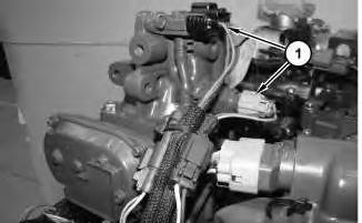
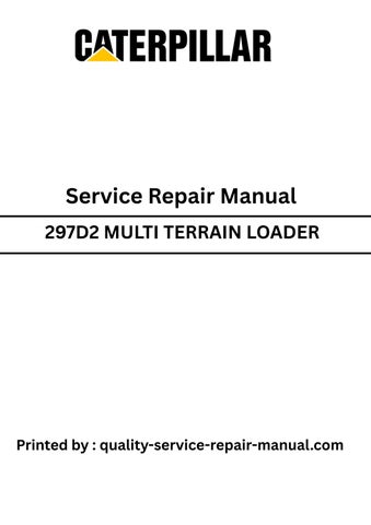
Illustration 1 g02870556 1. Disconnect harness assemblies (1).
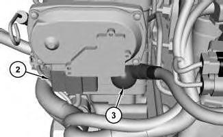
Illustration 2
g02870616
2. Disconnect harness assembly (2) and cable assembly (3).
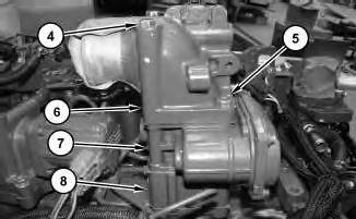
Illustration 3
g02870576
3. Remove bolts (4) and bolts (5). Remove flange (6), valve assembly (7), air inlet heater (8), and the gaskets.
Installation Procedure
1. Install new gaskets, air inlet heater (8), valve assembly (7), and flange (6) in the reverse order of removal.
a. Tighten the nut for cable assembly (3) to a torque of 4.4 ± 0.9 N·m (38.9 ± 8.0 lb in).
Copyright 1993 - 2020 Caterpillar Inc. All Rights Reserved. Private Network For SIS Licensees. Thu Jun 18 12:49:41 UTC+0530 2020
Product: MULTI TERRAIN LOADER
Model: 297D2 MULTI TERRAIN LOADER BL7
Configuration: 297D2 & 297D2 XHP Multi Terrain Loader BL700001-UP (MACHINE) POWERED BY C3.8 Engine
Disassembly and Assembly
C3.8 Engines for Caterpillar Built Machines
i06621882
Alternator - Remove and Install
SMCS - 1405-010
Removal Procedure
1. Refer to Operation and Maintenance Manual, "Radiator Tilting".
2. Refer to Operation and Maintenance Manual, "Belts - Inspect/Adjust/Replace".
3. Refer to Operation and Maintenance Manual, "Battery or Battery Cable - Inspect/Replace".
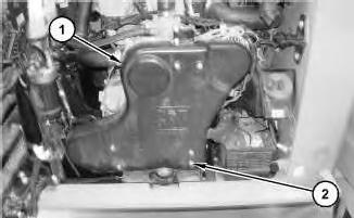
Illustration 1 g06050364 SSL, MTL, and CTL models.
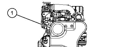
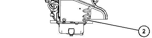
Illustration 2 g06050387 CWL models.
4. For SSL, MTL, and CTL models refer to illustration 1. Loosen quarter turn fasteners (2) and remove guard (1).
For the CWL models, refer to illustration 2. Remove bolts (2) and guard (1).
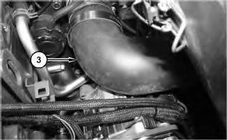
Illustration 3 g06050407
5. For the SSL, MTL, and CTL models, remove hose (3). For the CWL (910K/914K) go to Step 6.
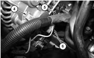
Illustration 4
g06050414
6. Disconnect wire assembly (4), cable assembly (5), and wire assembly (6).
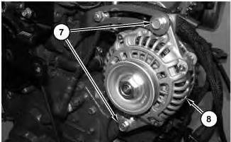
Illustration 5
7. Remove bolts (7). Remove alternator (8).
g06050420
Installation Procedure
1. Install alternator (8) in the reverse order of removal.
a. Tighten bolts (7) to a torque of 69 N·m ± 10 N·m (51 ± 7 lb ft). Copyright 1993 - 2020 Caterpillar Inc.
Product: MULTI TERRAIN LOADER
Model: 297D2 MULTI TERRAIN LOADER BL7
Configuration: 297D2 & 297D2 XHP Multi Terrain Loader BL700001-UP (MACHINE) POWERED BY C3.8 Engine
Disassembly and Assembly
C3.8 Engines for Caterpillar Built Machines
i06621308
Boost Pressure Sensor - Remove and Install
SMCS - 1917-010
Removal Procedure
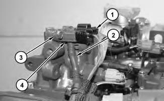
Illustration 1
g02893620
1. Disconnect harness assembly (1). Remove hose (2). Remove bolts (3) to remove boost pressure sensor (4).
Installation Procedure
1. Install boost pressure sensor (4) in the reverse order of removal.
a. Tighten bolts (3) to a torque of 4 N·m to 5 N·m (35 ± 44 lb in).
Thu Jun 18 13:14:22 UTC+0530 2020
This is the sample of the manual
Click on the download link for complete Manual

Product: MULTI TERRAIN LOADER
Model: 297D2 MULTI TERRAIN LOADER BL7
Configuration: 297D2 & 297D2 XHP Multi Terrain Loader BL700001-UP (MACHINE) POWERED BY C3.8 Engine
Disassembly and Assembly
C3.8 Engines for Caterpillar Built Machines Media Number -UENR0129-08 Publication Date -01/09/2015 Date Updated -19/05/2016
i04663730
Camshaft - Remove and Install
SMCS - 1210-010
Removal Procedure
Start By:
a. Remove the front housing.
b. Remove the rocker shaft and pushrods.
1. Refer to SystemsOperation, Testing and Adjusting, "Finding Top Center Position for No.4 Piston".
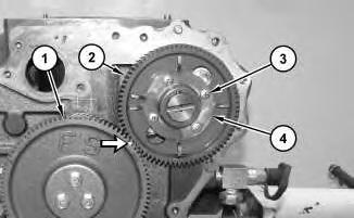
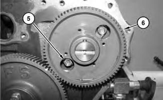
Illustration 1
2. Mark the alignment of gear (1) and gear (2) for installation purposes.
3. Remove bolts (3) and pulsar gear (4).
2
g02863959
4. Remove bolts (5). Remove camshaft assembly (6).
Installation Procedure
1. Lubricate the camshaft assembly with clean engine oil prior to installation.
2. Ensure that the camshaft assembly isclean and free from wear or damage.
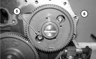
Illustration 3
g02863959
NOTICE
Do not damage the lobesor the bearingswhen the camshaft is removed or installed.
3. Install camshaft assembly (6). Install bolts (5). Tighten bolts(5) to a torque of 25.5 ± 1.5 N·m (18.8 ± 1.1 lb ft).
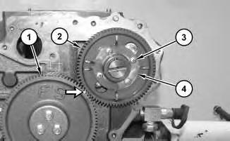
Illustration 4 g02864436
4. Install pulsar gear (4) and screws(3). Tighten screws (3) to a torque of 5.2 ±0.5 N·m (45.6 ± 4.0 lb in)Ensure that gear (1) and gear (2) are aligned.
5. Lubricate the teeth of the gearswith clean engine oil.
6. Refer to Specifications, "Camshaft" for more information.
End By:
a. Install the front housing.
b. Install the rocker shaft and pushrods.
Product: MULTI TERRAIN LOADER
Model: 297D2 MULTI TERRAIN LOADER BL7
Configuration: 297D2 & 297D2 XHP Multi Terrain Loader BL700001-UP (MACHINE) POWERED BY C3.8 Engine
Disassembly and Assembly
C3.8 Engines for Caterpillar Built Machines
Media Number -UENR0129-08 Publication Date -01/09/2015 Date Updated -19/05/2016
i04663712
Camshaft Gear - Remove and Install
SMCS - 1210-010-GE
Removal Procedure
Start By:
a. Remove the camshaft assembly from the engine.
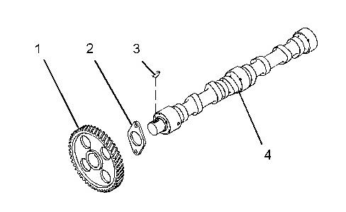
Illustration 1 g01350917
1. Place the camshaft assembly on a suitable support. Use a pressto remove camshaft gear (1) from camshaft (4).
2. Remove thrust plate (2) and woodruff key (3) from camshaft (4). Note the orientation of the thrust plate for installation.
Installation Procedure
1. Ensure that all components of the camshaft assembly are clean and free from damage.
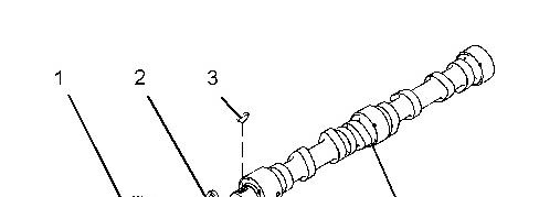

Illustration 2
2. Install woodruff key (3) and thrust plate (2) to camshaft (4).
g01350917
Note: Ensure that the machined face of the thrust plate istoward the camshaft.
Alwayswear protective gloves whenhandling partsthat have been heated.
3. Raise the temperature of camshaft gear (1). Align the camshaft gear with woodruff key (3) and install the camshaft gear to camshaft (4).
4. Refer to Specifications, "Camshaft" for more information.
End By:
a. Install the camshaft assembly to the engine. Copyright 1993 - 2020 Caterpillar Inc. All Rights Reserved.
Network For SIS Licensees. Thu Jun 18 13:08:56 UTC+0530 2020
Product: MULTI TERRAIN LOADER
Model: 297D2 MULTI TERRAIN LOADER BL7
Configuration: 297D2 & 297D2 XHP Multi Terrain Loader BL700001-UP (MACHINE) POWERED BY C3.8 Engine
Disassembly and Assembly
C3.8 Engines for Caterpillar Built Machines
Media Number -UENR0129-08 Publication Date -01/09/2015 Date Updated -19/05/2016
i04783390
Camshaft Position Sensor - Remove and Install
SMCS - 1912-010
Removal Procedure
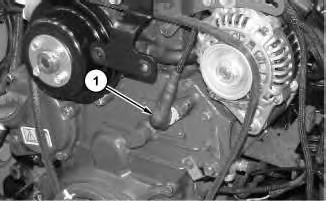
Illustration 1
g02893160 1. Disconnect harnessassembly (1).
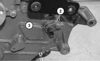
Illustration 2
2. Remove bolt (2) to remove position sensor (3) and the O-ring seal.
Installation Procedure
1. Install camshaft position sensor (3) and a new O-ring seal in the reverse order of removal.
a. Tighten bolt (2) to a torque of 4.5 ± 0.5 N·m (39.8 ± 4.4 lb in).
Copyright 1993 - 2020 Caterpillar Inc. All Rights Reserved. Private Network For SIS Licensees. Thu Jun 18 13:11:34 UTC+0530 2020
Product: MULTI TERRAIN LOADER
Model: 297D2 MULTI TERRAIN LOADER BL7
Configuration: 297D2 & 297D2 XHP Multi Terrain Loader BL700001-UP (MACHINE) POWERED BY C3.8 Engine
Disassembly and Assembly
C3.8 Engines for Caterpillar Built Machines
Catalyst (SCR) - Remove and Install
SMCS - 1091-010
S/N - BL21-UP
S/N - BL71-UP
S/N - BY41-UP
S/N - DX21-UP
S/N - DX91-UP
S/N - FD21-UP
S/N - HP21-UP
S/N - MD21-UP
Removal Procedure
Start By:
a. Remove radiator.
b. Remove air cooler.
c. Remove hydraulic oil cooler.
d. Remove DEF injector.
i06256854
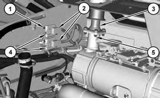
1
1. Disconnect harness assemblies (4). Remove bolts (1) and reposition sensors (2).
Note: The two NOx sensors have different color coded cables. The outlet NOx temperature sensor is gray and the inlet NOx sensor is black. Mark harness assemblies (4) to ensure that they are installed to the correct NOx sensor during reassembly.
2. Remove bolts (5) and exhaust extension (3).
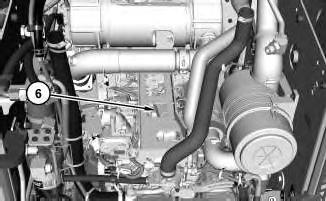
Illustration 2
3. Disconnect harness assembly (6) for the Pre NOx sensor, Post NOx Sensor, and SCR Inlet Temperature Sensor.
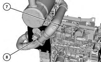
Illustration 3
4. Remove bolts (7) and bolts (8).
g03874298
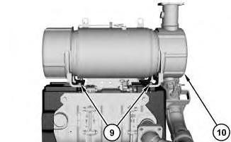
Illustration 4
g03874500
5. Use a suitable lifting device to remove catalyst assembly (10). The weight of catalyst assembly (10) is approximately ().
6. Remove bolts (9) and catalyst assembly (10).
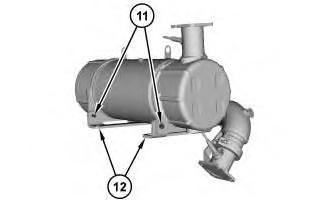
Illustration 5
7. Remove bolts (11) and brackets (12).
g03874645
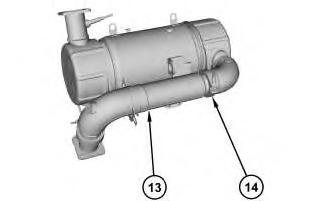
Illustration 6
g03874675
8. Remove clamp assembly (14) and pipe assembly (13).
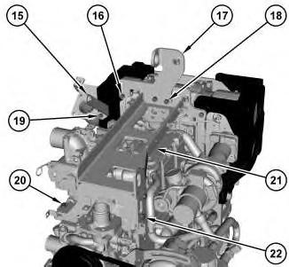
Illustration 7
g03874689
9. Remove bolts (18) and engine lifting eye (17).
10. Remove bolt (19) and bracket (15).
11. Remove bolts (16), bolt (20), bolts (22), and bracket assembly (21).
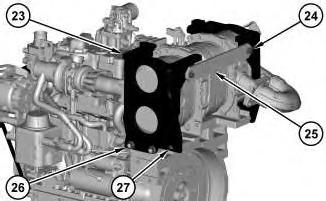
Illustration 8
12. Remove bolts (24) and bracket (25).
g03875070
13. Remove nuts (26), bolt (27), and base bracket (23).
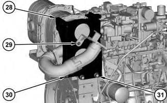
Illustration 9
g03875085
14. Remove bolt (29), bolt (30), nuts (31), and base bracket (28).
Installation Procedure
1. Install catalyst assembly (10) in the reverse order of removal.
a. Tighten nuts (31), bolt (30), bolt (29), bolt (27), nuts (26) to a torque of 124 - 147 N·m (91 - 108 lb ft).
b. Tighten bolts (22), bolts (20), bolt (19), bolts (16), and bolts (18) to a torque of 49 - 55 N·m (36 - 41 lb ft).
c. Tighten clamp assembly (14) and clamp assembly (13) to a torque of 15 ± 2 N·m (133 ± 18 lb in).
d. Tighten bolts (11), bolts (9), bolts (8), and bolts (7) to a torque of 49 - 55 N·m (36 - 41 lb ft).
Copyright 1993 - 2020 Caterpillar Inc. All Rights Reserved. Private Network For SIS Licensees.
Thu Jun 18 12:48:46 UTC+0530 2020
Product: MULTI TERRAIN LOADER
Model: 297D2 MULTI TERRAIN LOADER BL7
Configuration: 297D2 & 297D2 XHP Multi Terrain Loader BL700001-UP (MACHINE) POWERED BY C3.8 Engine
Disassembly and Assembly
C3.8 Engines for Caterpillar Built Machines
Coolant Temperature Sensor - Remove and Install
SMCS - 1906-010
Removal Procedure
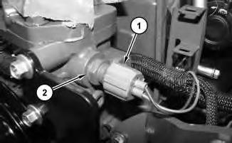
Illustration 1
1. Disconnect harness assembly (1) .
2. Remove coolant temperature sensor (2) .
Installation Procedure
g02851436
1. Install coolant temperature sensor (2) in the reverse order of removal.
a. Tighten temperature sensor (2) to a torque of 17.5 ± 5.5 N·m (155 ± 49 lb in).
i04815979
Product: MULTI TERRAIN LOADER
Model: 297D2 MULTI TERRAIN LOADER BL7
Configuration: 297D2 & 297D2 XHP Multi Terrain Loader BL700001-UP (MACHINE) POWERED BY C3.8 Engine
Disassembly and Assembly
C3.8 Engines for Caterpillar Built Machines
i06620851
Crankshaft - Install
SMCS - 1202-012
Installation Procedure
Table 1
- Three Bond 1217D -
1. Refer to Specifications, "Crankshaft" for more information. If necessary, replace the crankshaft or recondition the crankshaft.
2. Ensure that the parent bores for the crankshaft bearings in the cylinder block are clean. Ensure that the threads for the bearing bolts in the cylinder block are clean and free from damage.
3. Clean the crankshaft bearings and the thrust washers. Inspect the bearings and the thrust washers for wear or damage. If necessary, replace the bearingsand the thrust washers.
Note: If the crankshaft bearings are replaced, check whether oversize bearingswere previously installed. If the thrust washers are replaced, check whether oversize thrust washers were previously installed.
4. Ensure that all of the lubrication passages are clean and free of debris.
This is the sample of the manual
Click on the download link for complete Manual
1
g02861383
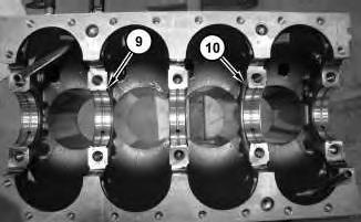
5. Install the upper thrust bearing (10) and the upper main bearings (9).
Note: The upper thrust bearing (10) is installed at the Number (4) bearing cap with the oil groove facing outward.
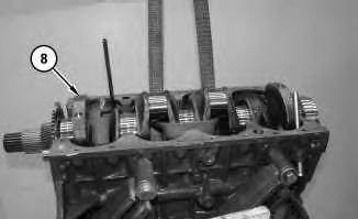
Illustration 2
g02861360
6. Use a suitable lifting device to install crankshaft (8). The weight of crankshaft (8) is approximately 32 kg (70 lb).
Note: Do not damage the finished surfaces on the crankshaft.