PreviousScreen
Product: COMPACT TRACK LOADER
Model: 289D COMPACT TRACK LOADER A9Z
Configuration: 289D Compact Track Loader A9Z00001-UP (MACHINE) POWERED BY C3.3B Engine
Disassembly and Assembly
C2.6 and C3.3B
Engines for Caterpillar Built Machines
Media Number -UENR0137-09
Alternator - Remove and Install
SMCS - 1405-010
S/N- A9W1-UP
S/N- A9Z1-UP
S/N- CE21-UP
S/N- DML1-UP
S/N- EML1-UP
S/N- F8C1-UP
S/N- FHL1-UP
S/N- FMR1-UP
S/N- FTK1-UP
S/N- GBJ1-UP
S/N- GTK1-UP
S/N- H1Y1-UP
S/N- HAM1-UP
S/N- HEL1-UP
Shutdown SIS
i05244466
S/N- HMR1-UP
S/N- JBE1-UP
S/N- JRD1-UP
S/N- JRF1-UP
S/N- JRS1-UP
S/N- JSL1-UP
S/N- JSN1-UP
S/N- KTS1-UP
S/N- L661-UP
S/N- L771-UP
S/N- L881-UP
S/N- LST1-UP
S/N- MLT1-UP
S/N- MPW1-UP
S/N- NTL1-UP
S/N- PPT1-UP
S/N- RCX1-UP
S/N- SEN1-UP
S/N- STK1-UP
S/N- TAZ1-UP
S/N- TLK1-UP
S/N- WCT1-UP
Removal Procedure
Start By: A. Remove V belt.
1. Turn the battery disconnect to the OFF position.
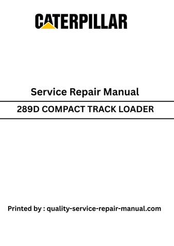
Illustration 1
2. Disconnect harnessassemblies(2) and (3) from alternator (1) .
3. Remove nut (4) .
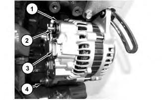
Illustration 2
4. Remove nut (7) and pulley (6) .
5. Remove bolts (5) and (6) .
6. Remove alternator (1) .
Installation Procedure
1. Install alternator (1) in the reverse order of removal.
g02798717
g02798718
a. Ensure pulley (6) is correctly oriented.
b. Tighten nut (7) to a torque of 58 to 79 N·m (43 to 58 lb ft).
Copyright 1993 - 2020 Caterpillar Inc. All Rights Reserved. Private Network For SIS Licensees. Mon May 18 13:46:19 UTC+0530 2020
PreviousScreen
Product: COMPACT TRACK LOADER
Model: 289D COMPACT TRACK LOADER A9Z
Configuration: 289D Compact Track Loader A9Z00001-UP (MACHINE) POWERED BY C3.3B Engine
Disassembly and Assembly
C2.6 and C3.3B
Engines for Caterpillar Built Machines
Bearing Clearance - Check
SMCS - 1203-535; 1219-535
Measurement Procedure
Table 1
Required Tools
198-9142
Shutdown SIS
198-9143
198-9144
Plastic Gauge (Green) 0.025 to 0.076 mm (0.001 to 0.003 inch)
Plastic Gauge (Red) 0.051 to 0.152 mm (0.002 to 0.006 inch)
Plastic Gauge (Blue) 0.102 to 0.229 mm (0.004 to 0.009 inch)
Plastic Gauge (Yellow)
to 0.510 mm (0.009 to 0.020 inch)
Note: Refer to Specification UENR0995 "Engine Design" for non-specified engine Torque Values.
Note: Plastic gauge may not be necessary when the engine is in the chassis.
i05242994
NOTICE
Keep all parts clean from contaminants.
Contaminants may cause rapid wear and shortened component life.
Note: Caterpillar does not recommend the checking of the actual bearing clearances particularly on small engines. The checking can result in the possibility of obtaining inaccurate information and the possibility of damaging the bearing or the journal surfaces. Each Caterpillar engine bearing is quality checked for specific wall thickness.
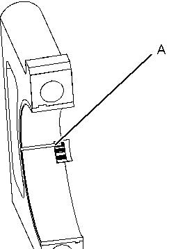
Note: The measurements should be within specifications and the correct bearings should be used. If the crankshaft journals and the bores for the block and the rods were measured during disassembly, no further checks are necessary. However, if the technician still wants to measure the bearing clearances, Tooling (A) is an acceptable method. Tooling (A) is less accurate on journalswith small diametersif clearancesare less than 0.10 mm (0.004 inch).
NOTICE
Lead wire, shim stock or a dial bore gauge can damage the bearing surfaces.
The technician must be careful to use Tooling (A) correctly. The following points must be remembered:
• Ensure that the backs of the bearings and the bores are clean and dry.
• Ensure that the bearing locking tabs are properly seated in the tab grooves.
• The crankshaft must be free of oil at the contact pointsof Tooling (A).
1. Put a piece of Tooling (A) on the crown of the bearing that is in the cap.
Note: Do not allow Tooling (A) to extend over the edge of the bearing.
2. Use the correct torque-turn specifications in order to install the bearing cap. Do not use an impact wrench. Be careful not to dislodge the bearing when the cap isinstalled.
Note: Do not turn the crankshaft when Tooling (A) is installed.
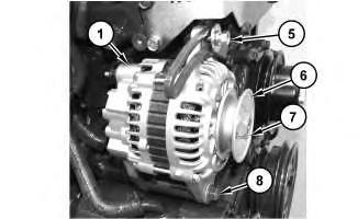
3. Carefully remove the cap, but do not remove Tooling (A). Measure the width of Tooling (A) while Tooling (A) is in the bearing cap or on the crankshaft journal. Refer to Illustration 1.
This is the sample of the manual
Click on the download link for complete Manual
Illustration 1 g01152855
TypicalExample
4. Remove all of Tooling (A) before you install the bearing cap.
Note: When Tooling (A) is used, the readings can sometimes be unclear. For example, all parts of Tooling (A) are not the same width. Measure the major width in order to ensure that the parts are within the specification range. Refer to SpecificationsManual, "Connecting Rod Bearing Journal" and Specifications Manual, "Main Bearing Journal" for the correct clearances.
Copyright 1993 - 2020 Caterpillar Inc. All Rights Reserved. Private Network For SIS Licensees. Mon May 18 13:45:35 UTC+0530 2020
PreviousScreen
Product: COMPACT TRACK LOADER
Model: 289D COMPACT TRACK LOADER A9Z
Configuration: 289D Compact Track Loader A9Z00001-UP (MACHINE) POWERED BY C3.3B Engine
Disassembly and Assembly
C2.6 and C3.3B
Engines for Caterpillar Built Machines
Media Number -UENR0137-09
Bridge Dowels - Remove and Install - C3.3B
SMCS - 1100-010
S/N- A9W1-UP
S/N- A9Z1-UP
S/N- CE21-UP
S/N- DML1-UP
S/N- EML1-UP
S/N- F8C1-UP
S/N- FMR1-UP
S/N- FTK1-UP
S/N- GBJ1-UP
S/N- GTK1-UP
S/N- HAM1-UP
S/N- HEL1-UP
S/N- HMR1-UP
S/N- JBE1-UP
Shutdown SIS
i05242591
S/N- JRD1-UP
S/N- JRF1-UP
S/N- JRS1-UP
S/N- JSL1-UP
S/N- JSN1-UP
S/N- KTS1-UP
S/N- L661-UP
S/N- L771-UP
S/N- L881-UP
S/N- LST1-UP
S/N- MLT1-UP
S/N- MPW1-UP
S/N- NTL1-UP
S/N- PPT1-UP
S/N- RCX1-UP
S/N- SEN1-UP
S/N- STK1-UP
S/N- TAZ1-UP
S/N- TLK1-UP
S/N- WCT1-UP
Removal Procedure
Table 1
Required Tools
Start By:
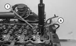
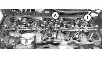
A. Remove valve springs of bridge dowel being repaired.
Note: Refer to Specification UENR0995 "Engine Design" for non-specified engine Torque Values.
1
1. Install Tooling (A) and remove bridge dowel (1) .
Installation Procedure
Table 2
Illustration
g02882621
Illustration 2
g02882716
Illustration 3
g02882838
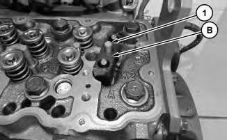
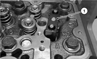
1. Use a press or hammer to drive bridge dowel (1) to a height that is flush with Tooling (B) .
End By: Install valve springsof bridge dowel being repaired.
Copyright 1993 - 2020 Caterpillar Inc. All Rights Reserved. Private Network For SIS Licensees. Mon May 18 13:43:09 UTC+0530 2020
PreviousScreen
Product: COMPACT TRACK LOADER
Model: 289D COMPACT TRACK LOADER A9Z
Configuration: 289D Compact Track Loader A9Z00001-UP (MACHINE) POWERED BY C3.3B Engine
Disassembly and Assembly
C2.6 and C3.3B
Engines for Caterpillar Built Machines
Media Number -UENR0137-09
Shutdown SIS
Camshaft and Valve Lifters - Remove and Install - C3.3B
SMCS - 1209-010; 1210-010
S/N- A9W1-UP
S/N- A9Z1-UP
S/N- CE21-UP
S/N- DML1-UP
S/N- EML1-UP
S/N- F8C1-UP
S/N- FMR1-UP
S/N- FTK1-UP
S/N- GBJ1-UP
S/N- GTK1-UP
S/N- HAM1-UP
S/N- HEL1-UP
S/N- HMR1-UP
S/N- JBE1-UP
i05242925
S/N- JRD1-UP
S/N- JRF1-UP
S/N- JRS1-UP
S/N- JSL1-UP
S/N- JSN1-UP
S/N- KTS1-UP
S/N- L661-UP
S/N- L771-UP
S/N- L881-UP
S/N- LST1-UP
S/N- MLT1-UP
S/N- MPW1-UP
S/N- NTL1-UP
S/N- PPT1-UP
S/N- RCX1-UP
S/N- SEN1-UP
S/N- STK1-UP
S/N- TAZ1-UP
S/N- TLK1-UP
S/N- WCT1-UP
Removal Procedure
Table 1 RequiredTools Tool Part Number
Description
A - Magnets 8
B 390-1149 Driver 1
Start By:
A. Remove the rocker shaft and pushrods.
B. Remove the flywheel housing.
C. Remove the oil pan. (Only necessary if valve lifters will be removed.)
Note: Refer to Specification UENR0995 "Engine Design" for non-specified engine Torque Values.
NOTICE
Keep all parts clean from contaminants.
Contaminants may cause rapid wear and shortened component life.
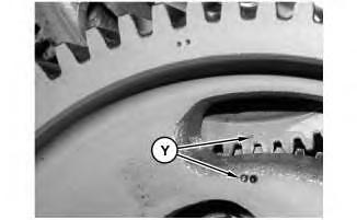
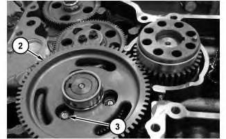
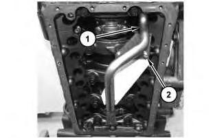
Illustration 1
g02795978
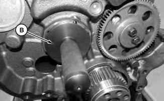
1. Ensure that Timing Marks (Y) on the idler gear and the camshaft gear are aligned. Refer to illustration 1.
2
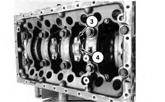
2. Use Tooling (A) to hold up the valve lifters (1) in order to remove the camshaft.
3
Do not damage the lobesor the bearingswhen the camshaft is removed or installed.
3. Remove bolts (3) .
4. Carefully remove camshaft (2) from the cylinder block.
5. Remove Tooling (A) . Use a suitable container to catch the valve lifters(1) asthe valve lifters (1) slide out the bottom of the cylinder block.
Illustration
g02798975
Illustration
g02796757
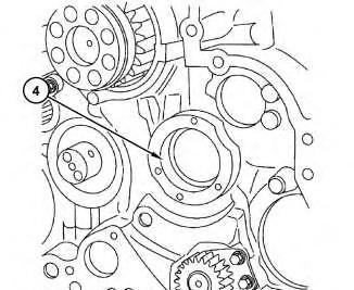
Illustration 4 g02880896
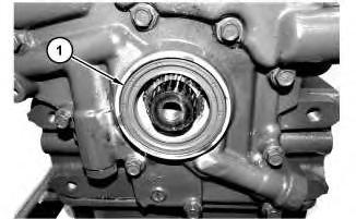
6. Remove the camshaft cover (4) .
Installation Procedure
1. Install camshaft (1) in the reverse order of removal.
5
Illustration
g02881018
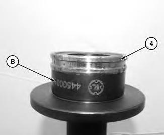
a. Place camshaft cover (4) on Tooling (B) .
Illustration 6 g02881076
b. Use Tooling (B) to install the camshaft cover (4) .
c. Tighten bolts (3) to a torque of 24.0 ± 27.0 N·m (17.70 ± 19.91 lb ft).
Copyright 1993 - 2020 Caterpillar Inc. All Rights Reserved. Private Network For SIS Licensees.
Mon May 18 13:43:56 UTC+0530 2020
PreviousScreen
Product: COMPACT TRACK LOADER
Model: 289D COMPACT TRACK LOADER A9Z
Configuration: 289D Compact Track Loader A9Z00001-UP (MACHINE) POWERED BY C3.3B Engine
Disassembly and Assembly
C2.6 and C3.3B
Engines for Caterpillar Built Machines
Media Number -UENR0137-09
Camshaft Gear - Remove and Install
SMCS - 1210-010-GE
Removal Procedure
Table 1
RequiredTools
Tool Part Number Part Description Qty
A 1P-0510 Driver Group 1
B 8B-7551 Puller Assembly 1
C 8H-0663 Bearing Puller 1
Start By:
A. Remove the camshaft.
Shutdown SIS
Note: Refer to Specification UENR0995 "Engine Design" for non-specified engine Torque Values.
NOTICE
Care must be taken to ensure that fluidsare contained during performance of inspection, maintenance, testing, adjusting and repair of the product. Be prepared to collect the fluid with suitable containers before opening any compartment or disassembling any component containing fluids.
i05242932
Dispose of all fluids according to local regulationsand mandates.
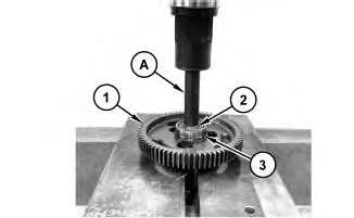
Illustration 1
g02796778
1. Use Tooling (A) in order to remove camshaft gear (1) from camshaft (2) .
2. If necessary, apply heat to raise the temperature of the race (3) of the roller bearing to remove.
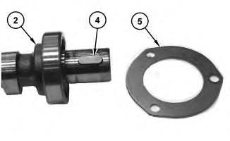
Illustration 2
3. Remove plate (5) from camshaft (2) .
g02796779
4. If necessary, remove the key (4) from the nose of camshaft (2) .
Installation Procedure
1. Install camshaft gear (1) in the reverse order of removal.
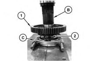
Illustration 3 g02807848
a. Use Tooling (B) and Tooling (C) in order to install camshaft gear (1) onto camshaft (2) .
b. Ensure that the camshaft gear and the key are clean and free from wear and damage.
Copyright 1993 - 2020 Caterpillar Inc. All Rights Reserved. Private Network For SIS Licensees. Mon May 18 13:44:08 UTC+0530 2020
PreviousScreen
Product: COMPACT TRACK LOADER
Model: 289D COMPACT TRACK LOADER A9Z
Configuration: 289D Compact Track Loader A9Z00001-UP (MACHINE) POWERED BY C3.3B Engine
Disassembly and Assembly
C2.6 and C3.3B
Engines for Caterpillar Built Machines
Connecting Rod Bearings - Remove and Install
SMCS - 1219-010
Removal Procedure
Start By:
a. Remove the engine oil pan.
Shutdown SIS
Note: Refer to Specification UENR0995 "Engine Design" for non-specified engine Torque Values.
NOTICE
Keep all parts clean from contaminants.
Contaminants may cause rapid wear and shortened component life.
NOTICE
Discard all used Connecting Rod fasteners.
Note: If all connecting rod bearings require replacement, the procedure can be carried out on two cylindersat the same time. The procedure can be carried out on the following pairs of cylinders. 1
i06892088
with 4 and 2 with 3. Ensure that both pairsof the connecting rod bearingsare installed before changing from one pair of cylinders to another pair of cylinders. Refer to Disassembly and Assembly, "Connecting Rod Bearings- Install" for the correct procedure.
Illustration 1
g02798265
1. Remove bolt (2), the O-ring seal, and oil pump screen (1).
Illustration 2
g02798267
2. The connecting rod and the connecting rod cap should have an etched Number (X) on the side. The number on the connecting rod and the connecting rod cap must match. If necessary, make a temporary mark on the connecting rod and connecting rod cap (4) in order to identify the cylinder number.
3. Remove bolts (3). Remove connecting rod cap (4) from the connecting rod.
Illustration 3
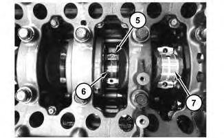
4. Carefully push connecting rod (5) into the cylinder bore until connecting rod (5) is clear of the crankshaft. Remove lower bearing shell (7) and then remove upper bearing shell (6) from connecting rod (5). Keep the bearing shellstogether.
5. Repeat Step 3 through Step 4 for the remaining bearing shells.
Installation Procedure
NOTICE
Keep all parts clean from contaminants.
Contaminants may cause rapid wear and shortened component life.
NOTICE
Discard all used Connecting Rod fasteners.
1. Ensure that the bearing shells are clean and free from wear and damage. If necessary, replace the bearing shells.
Illustration 4
Illustration 5
g02798267
Note: Connecting rods and bearing are marked with color codes. The color codesare blue and unmarked. The bearings must match up with the corresponding connecting rods. It is possible to have different color codesin the same engine.
2. Install upper bearing shell (6) into connecting rod (5). Ensure that the locating tab for the upper bearing shell is correctly seated in the slot in connecting rod (5).
Note: The ends of the upper bearing shell must be centered in the connecting rod. The endsof the upper bearing shell are to be positioned equally in relation to the mating faces of the connecting rod.
3. Lubricate upper bearing shell (6) with clean engine oil.
4. Carefully pull connecting rod (5) against the crankshaft.
5. Clean connecting rod cap (4). Install lower bearing shell (7) into connecting rod cap (4). Ensure that the locating tab for lower bearing shell (7) iscorrectly seated in the slot in connecting rod cap (4).
6. Lubricate the crankshaft and lubricate lower bearing shell (7) with clean engine oil.
g02798268
7. Install connecting rod cap (4) to the connecting rod.
Note: Ensure that etched Number on connecting rod cap (4) matches etched Number on the connecting rod. Ensure the correct orientation of the connecting rod cap. The locating tab for the upper bearing shell and the lower bearing shell should be on the same side.
8. For the C3.3B install new bolts(3) to the connecting rod. Apply clean engine oil to the threads of bolts. Tighten the bolts evenly to a torque of 69 to 73 N·m (51 to 54 lb ft).
9. For the C2.6 install new bolts(3) to the connecting rod. Apply clean engine oil to the threads of bolts. Tighten the bolts evenly to a torque of 45 to 49 N·m (33 to 36 lb ft).
Illustration 6
g02798265
10. Position engine oil screen (1) and install the O-ring seal and bolt (2).
11. Repeat Step 2 through Step 8 for the remaining connecting rod bearings.
Note: If all connecting rod bearings require replacement, the procedure can be carried out on two cylindersat the same time. The procedure can be carried out on the following pairs of cylinders. 1 with 4 and 2 with 3. Ensure that both pairsof the connecting rod bearingsare installed before changing from one pair of cylinders to another pair of cylinders. Refer to Disassembly and Assembly, "Connecting Rod Bearings - Install" for the correct procedure.
End By:
a. Install the engine oil pan.
Copyright 1993 - 2020 Caterpillar Inc.
PreviousScreen
Product: COMPACT TRACK LOADER
Model: 289D COMPACT TRACK LOADER A9Z
Configuration: 289D Compact Track Loader A9Z00001-UP (MACHINE) POWERED BY C3.3B Engine
Disassembly and Assembly
C2.6 and C3.3B
Engines for Caterpillar Built Machines
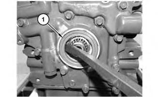
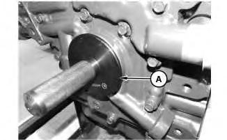
Crankshaft Front Seal - Remove and Install
SMCS - 1160-010
Removal Procedure
Start By:
A. Remove the crankshaft pulley.
Note: Refer to Specification UENR0995 "Engine Design" for non-specified engine Torque Values.
NOTICE
Care must be taken to ensure that fluidsare contained during performance of inspection, maintenance, testing, adjusting and repair of the product. Be prepared to collect the fluid with suitable containers before opening any compartment or disassembling any component containing fluids.
Dispose of all fluids according to local regulationsand mandates.
i05242559
1
2
1. Use a suitable pry bar to remove crankshaft front seal (1) .
Installation Procedure
Table 1
RequiredTools
Note: The crankshaft front seal should be installed dry. Lubricate the inner rubber portion of the crankshaft front seal.
Illustration
g02795123
Illustration
g02795124
Illustration 3
Illustration 4
1. Lubricate the inner rubber portion of crankshaft front seal (1) . Apply Tooling (B) on crankshaft front seal (1) . Position crankshaft front seal (1) on Tooling (A) . Install crankshaft front seal (1) on the crankshaft.
End By: Install the crankshaft pulley.
Copyright 1993 - 2020 Caterpillar Inc. All Rights Reserved. Private Network For SIS Licensees. Mon May 18 13:42:07 UTC+0530 2020
g02796112
g02795123
This is the sample of the manual
Click on the download link for complete Manual
PreviousScreen
Product: COMPACT TRACK LOADER
Model: 289D COMPACT TRACK LOADER A9Z
Configuration: 289D Compact Track Loader A9Z00001-UP (MACHINE) POWERED BY C3.3B Engine
Disassembly and Assembly
C2.6 and C3.3B
Engines for Caterpillar Built Machines
Crankshaft Pulley - Remove and Install
SMCS - 1205-010
Removal Procedure
Start By:
A. Remove the v-belt.
Note: Refer to Specification UENR0995 "Engine Design" for non-specified engine Torque Values.
NOTICE
Keep all parts clean from contaminants.
Contaminants may cause rapid wear and shortened component life.
i05242553