

Previous Screen

Product: NO EQUIPMENT SELECTED
Model: NO EQUIPMENT SELECTED
Configuration: NO EQUIPMENT SELECTED
Disassembly and Assembly
C3.4 Engines for Caterpillar Built Machines
MediaNumber-KENR6941-04
PublicationDate-01/03/2012
Alternator - Remove and Install
SMCS - 1405-010
Removal Procedure
Start By:

Shutdown SIS
DateUpdated-01/03/2012
i02639317
Remove the V-Belt. Refer to Disassembly and Assembly, "V-Belts - Remove and Install". A.
NOTICE
Keep all parts clean from contaminants.
Contaminants may cause rapid wear and shortened component life.
Turn the battery disconnect switch to the OFF position. 1.
Make temporary identification marks on the connections of the harness assembly. 2.
https://127.0.0.1/sisweb/sisweb/techdoc/techdoc_print_page.jsp?returnurl=/sisweb/sisweb
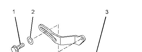
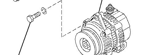
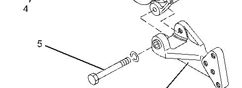

Illustration 1g01343570
Typical Example
3.
Disconnect the harness assembly from alternator (3) .
Loosen bolt (4). Remove bolt (1) and washer (2) from alternator (3) .
4. Remove bolt (5) from alternator (3). Remove the alternator from alternator bracket (6) .
5. Installation Procedure
https://127.0.0.1/sisweb/sisweb/techdoc/techdoc_print_page.jsp?returnurl=/sisweb/sisweb
Illustration 2g01343570
Typical example
1. Install bolt (1) and washer (2) finger tight.
Position alternator (3) on bracket (6) and install bolt (5) finger tight.
2.
3.
Install the V-belt. Refer to Disassembly and assembly, "V-belts - Remove and Install" for the correct procedure.
4.
Tighten bolts (1) and (4) to a torque of 11 N·m (97 lb in). Tighten bolt (5) to a torque of 35 N·m (26 lb ft).
5.
Connect the harness assembly to alternator (3) .
https://127.0.0.1/sisweb/sisweb/techdoc/techdoc_print_page.jsp?returnurl=/sisweb/sisweb
Turn the battery disconnect switch to the ON position.
https://127.0.0.1/sisweb/sisweb/techdoc/techdoc_print_page.jsp?returnurl=/sisweb/sisweb
Previous Screen
Product: NO EQUIPMENT SELECTED
Model: NO EQUIPMENT SELECTED
Configuration: NO EQUIPMENT SELECTED
Disassembly and Assembly
C3.4 Engines for Caterpillar Built Machines
MediaNumber-KENR6941-04
PublicationDate-01/03/2012
DateUpdated-01/03/2012
Balancer - Assemble
SMCS - 1220-016
Assembly Procedure Required Tools
NOTICE
Keep all parts clean from contaminants.
Contaminants may cause rapid wear and shortened component life.
Ensure that all components of the balancer are clean and free from damage. 1.
https://127.0.0.1/sisweb/sisweb/techdoc/techdoc_print_page.jsp?returnurl=/sisweb/sisweb
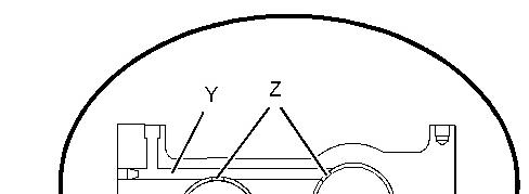
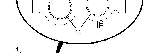
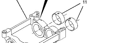

Illustration 1g01344574
If new bushing (11) is installed to the balancer, follow Steps 2.a and 2.b.
2. Align oil holes (Z) in bushing (11) to drilling (Y) in balancer (1) .
b.
a. Use Tooling (C) to install bushing (11) to balancer (1). Ensure that the oil holes (Z) are correctly aligned to drilling (Y) .
https://127.0.0.1/sisweb/sisweb/techdoc/techdoc_print_page.jsp?returnurl=/sisweb/sisweb
This is the sample of the manual
Click on the download link for complete Manual
3.
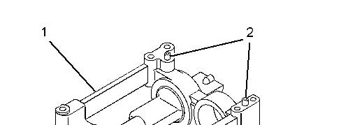
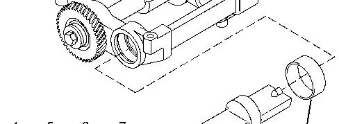
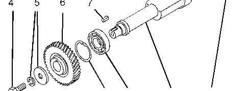

Illustration 2g01344515
Use Tooling (C) in order to press bearings (9) into balancer (1) .
Note: Do not press on the inner race of the bearing as this could result in damage to the bearing.
4.
Use Tooling (B) to install retaining rings (8) .
Note: Ensure that the retaining rings are fully located into the grooves in the balancer.
5.
Lubricate balancer shafts (10) and bushing (11) with clean engine oil. Carefully install the balancer shafts to balancer (1) .
6.
Install keys (7) .
https://127.0.0.1/sisweb/sisweb/techdoc/techdoc_print_page.jsp?returnurl=/sisweb/sisweb
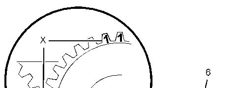


Illustration 3g01344665
Timing marks
Align gears (6) with keys (7) and install the gears to balancer shafts (10). Ensure that the gears are installed in the correct position. 7.
Note: The gears have different Markings (X). The right hand gear is marked 1,1 and 2,2. The left hand gear is marked 2. Refer to Illustration 3.
Apply Tooling (D) to the threads of bolts (4). Install bolts (4) and washers (5). Tighten the bolts to a torque of 33 N·m (24 lb ft). 8.
https://127.0.0.1/sisweb/sisweb/techdoc/techdoc_print_page.jsp?returnurl=/sisweb/sisweb
Previous Screen
Product: NO EQUIPMENT SELECTED
Model: NO EQUIPMENT SELECTED
Configuration: NO EQUIPMENT SELECTED
Disassembly and Assembly
C3.4 Engines for Caterpillar Built Machines
MediaNumber-KENR6941-04
PublicationDate-01/03/2012
DateUpdated-01/03/2012
Balancer - Disassemble
SMCS - 1220-015
Disassembly Procedure
Required Tools
Keep all parts clean from contaminants.
Contaminants may cause rapid wear and shortened component life.
https://127.0.0.1/sisweb/sisweb/techdoc/techdoc_print_page.jsp?returnurl=/sisweb/sisweb
Illustration 1g01344515
https://127.0.0.1/sisweb/sisweb/techdoc/techdoc_print_page.jsp?returnurl=/sisweb/sisweb
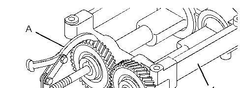
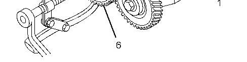
Illustration 2g01344528
Illustration 3g01344665
https://127.0.0.1/sisweb/sisweb/techdoc/techdoc_print_page.jsp?returnurl=/sisweb/sisweb
Timing marks
1.
Remove bolts (4) and washers (5). Use Tooling (A) in order to remove gears (6). Ensure that balancer shaft (10) is protected from damage.
Note: Gears (6) have different Markings (X). Refer to Illustration 3. Identify the position of the gears for installation.
Remove keys (7). Use Tooling (B) in order to remove retaining rings (8) .
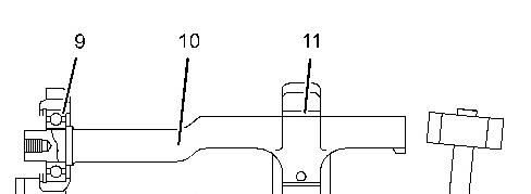
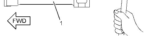
Illustration 4g01344533
3. Use Tooling (A) in order to remove bearing (9) from balancer shaft (10) . 4.
Carefully tap the assembly of bearing (9) and balancer shaft (10) forward until the shaft is clear of bushing (11). Refer to Illustration 4.
Note: Ensure that the balancer shaft is protected from damage.
Slide balancer shaft (10) back through bushing (11) until the shaft is clear of the balancer. 5. If necessary, use Tooling (C) in order to remove bushing (11) from balancer (1) .
https://127.0.0.1/sisweb/sisweb/techdoc/techdoc_print_page.jsp?returnurl=/sisweb/sisweb
Previous Screen
Product: NO EQUIPMENT SELECTED
Model: NO EQUIPMENT SELECTED
Configuration: NO EQUIPMENT SELECTED
Disassembly and Assembly
C3.4 Engines for Caterpillar Built Machines
MediaNumber-KENR6941-04
PublicationDate-01/03/2012
Balancer - Install
SMCS - 1220-012
Installation Procedure
Table 1
Required Tools
Tool
9U-7324 Indicator Bracket 1
7H-1942 Dial Indicator 1
3S-3268 Indicator Contact Point 1
7H-1940 Universal Attachment 1
Shutdown SIS
DateUpdated-01/03/2012
i02639299
NOTICE
Keep all parts clean from contaminants.
Contaminants may cause rapid wear and shortened component life.
https://127.0.0.1/sisweb/sisweb/techdoc/techdoc_print_page.jsp?returnurl=/sisweb/sisweb
Illustration 1g01344665
Timing marks
https://127.0.0.1/sisweb/sisweb/techdoc/techdoc_print_page.jsp?returnurl=/sisweb/sisweb
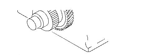
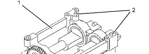
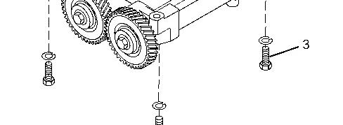

Illustration 2g01344983
Ensure that dowels (2) are seated in balancer (1). Ensure that marks 2,2 and 2 on gears (6) are aligned. Refer to Illustration 1. 1.
https://127.0.0.1/sisweb/sisweb/techdoc/techdoc_print_page.jsp?returnurl=/sisweb/sisweb
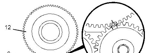
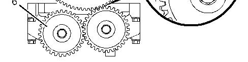
Illustration 3g01344971
Alignment of the timing marks
2. Install bolts (3). Tighten the bolts to a torque of 30 N·m (22 lb ft).
Align dowels (2) with the holes in the cylinder block. Align mark 1,1 on gear (6) to mark 1 on crankshaft gear (12). Refer to Illustration 3. Position balancer (1) on the engine. The balancer weighs approximately 23 kg (51 lb).
3.
4.
Use Tooling (F) in order to check the backlash between gears (6). Refer to Specifications, "Gear Group (Front)".
5.
Use Tooling (F) in order to check the backlash between gears (6) and (12). Refer to Specifications, "Gear Group - Front" for further information.
End By: Install the engine oil pan. Refer to Disassembly and Assembly, " Engine Oil Pan - Remove and Install".
1993 - 2018 Caterpillar Inc.
https://127.0.0.1/sisweb/sisweb/techdoc/techdoc_print_page.jsp?returnurl=/sisweb/sisweb
Previous Screen
Product: NO EQUIPMENT SELECTED
Model: NO EQUIPMENT SELECTED
Configuration: NO EQUIPMENT SELECTED
Disassembly and Assembly
C3.4 Engines for Caterpillar Built Machines
MediaNumber-KENR6941-04
Balancer - Remove
SMCS - 1220-011
Removal Procedure
Start By:
PublicationDate-01/03/2012
Shutdown SIS
DateUpdated-01/03/2012 i02639298
Remove the engine oil pan and remove the oil strainer. Refer to Disassembly and Assembly, "Engine Oil Pan - Remove and Install". A.
NOTICE
Keep all parts clean from contaminants.
Contaminants may cause rapid wear and shortened component life.
NOTICE
Care must be taken to ensure that fluids are contained during performance of inspection, maintenance, testing, adjusting and repair of the product. Be prepared to collect the fluid with suitable containers before opening any compartment or disassembling any component containing fluids.
Dispose of all fluids according to local regulations and mandates.
https://127.0.0.1/sisweb/sisweb/techdoc/techdoc_print_page.jsp?returnurl=/sisweb/sisweb
Ensure that number one piston is at the top center position on the compression stroke. Refer to Systems Operation, Testing and Adjusting, "Finding Top Center Position for No. 1 Piston". 1.
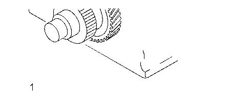
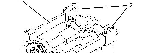
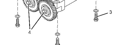

Illustration 1g01344508
Note: If the balancer will be disassembled, loosen bolts (4) before the balancer is removed from the engine.
2.
Support the weight of the balancer. The balancer weighs approximately 23 kg (51 lb). Remove bolts (3) and remove balancer (1) from the engine.
3.
Do not remove dowels (2) unless the dowels are damaged.
https://127.0.0.1/sisweb/sisweb/techdoc/techdoc_print_page.jsp?returnurl=/sisweb/sisweb
https://127.0.0.1/sisweb/sisweb/techdoc/techdoc_print_page.jsp?returnurl=/sisweb/sisweb
Previous Screen
Product: NO EQUIPMENT SELECTED
Model: NO EQUIPMENT SELECTED
Configuration: NO EQUIPMENT SELECTED
Disassembly and Assembly
C3.4 Engines for Caterpillar Built Machines
MediaNumber-KENR6941-04
PublicationDate-01/03/2012
Bearing Clearance - Check
SMCS - 1203-535; 1219-535
Measurement Procedure Required Tools Tool
Table 1
198-9142
198-9143
198-9144
Plastic Gauge (Green)
to 0.076 mm (0.001 to 0.003 inch)
Plastic Gauge (Red) 0.051 to 0.152 mm (0.002 to 0.006 inch)
Plastic Gauge (Blue) 0.102 to 0.229 mm (0.004 to 0.009 inch)
198-9145
Plastic Gauge (Yellow) 0.230 to 0.510 mm (0.009 to 0.020 inch)
Note: Plastic gauge may not be necessary when the engine is in the chassis.
NOTICE
Keep all parts clean from contaminants.
DateUpdated-01/03/2012
https://127.0.0.1/sisweb/sisweb/techdoc/techdoc_print_page.jsp?returnurl=/sisweb/sisweb
Contaminants may cause rapid wear and shortened component life.
Note: Cat does not recommend the checking of the actual bearing clearances particularly on small engines. This is because of the possibility of obtaining inaccurate results and the possibility of damaging the bearing or the journal surfaces. Each Cat engine bearing is quality checked for specific wall thickness.
Note: The measurements should be within specifications and the correct bearings should be used. If the crankshaft journals and the bores for the block and the rods were measured during disassembly, no further checks are necessary. However, if the technician still wants to measure the bearing clearances, Tooling (A) is an acceptable method. Tooling (A) is less accurate on journals with small diameters if clearances are less than 0.10 mm (0.004 inch).
NOTICE
Lead wire, shim stock or a dial bore gauge can damage the bearing surfaces.
The technician must be very careful to use Tooling (A) correctly. The following points must be remembered:
Ensure that the backs of the bearings and the bores are clean and dry.
Ensure that the bearing locking tabs are properly seated in the tab grooves.
The crankshaft must be free of oil at the contact points of Tooling (A).
1.
Put a piece of Tooling (A) on the crown of the bearing that is in the cap.
Note: Do not allow Tooling (A) to extend over the edge of the bearing.
2.
Use the correct torque-turn specifications in order to install the bearing cap. Do not use an impact wrench. Be careful not to dislodge the bearing when the cap is installed.
Note: Do not turn the crankshaft when Tooling (A) is installed.
3.
Carefully remove the cap, but do not remove Tooling (A). Measure the width of Tooling (A) while Tooling (A) is in the bearing cap or on the crankshaft journal. Refer to Illustration 1.
https://127.0.0.1/sisweb/sisweb/techdoc/techdoc_print_page.jsp?returnurl=/sisweb/sisweb
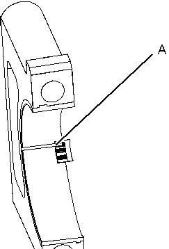

Illustration 1g01152855
Typical Example
Remove all of Tooling (A) before you install the bearing cap. 4.
Note: When Tooling (A) is used, the readings can sometimes be unclear. For example, all parts of Tooling (A) are not the same width. Measure the major width in order to ensure that the parts are within the specification range. Refer to Specifications Manual, "Connecting Rod Bearing Journal" and Specifications Manual, "Main Bearing Journal" for the correct clearances.
Copyright 1993 - 2018 Caterpillar Inc. All Rights Reserved. Private Network For SIS Licensees. Wed Nov 21 13:44:11
https://127.0.0.1/sisweb/sisweb/techdoc/techdoc_print_page.jsp?returnurl=/sisweb/sisweb
Previous Screen
Product: NO EQUIPMENT SELECTED
Model: NO EQUIPMENT SELECTED
Configuration: NO EQUIPMENT SELECTED
Disassembly and Assembly
C3.4 Engines for Caterpillar Built Machines
MediaNumber-KENR6941-04
PublicationDate-01/03/2012
Camshaft - Remove and Install
SMCS - 1210-010
Removal Procedure
Start By:
Shutdown SIS
DateUpdated-01/03/2012
i02639294
Remove the front housing. Refer to Disassembly and Assembly, "Housing (Front) - Remove and Install".
NOTICE
Keep all parts clean from contaminants.
Contaminants may cause rapid wear and shortened component life.
The engine should be mounted on a suitable stand and placed in the inverted position.
Rotate the crankshaft so that number one piston is at the top center position on the compression stroke. Refer to Systems Operation, Testing and Adjusting, "Finding Top Center Position for No.1 Piston".
Remove the rocker shaft and pushrods. Refer to Disassembly and Assembly, "Rocker Shaft and Pushrod - Remove".
https://127.0.0.1/sisweb/sisweb/techdoc/techdoc_print_page.jsp?returnurl=/sisweb/sisweb
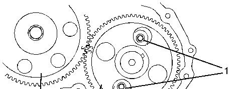
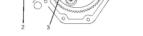
Illustration 1g01349741
Typical example
Ensure that gears (2) and (3) are marked in order to show alignment. Refer to Illustration 1. 4.
Note: Identification will ensure that the camshaft can be installed in the original position. Remove bolts (1) . 5.
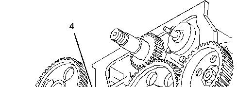
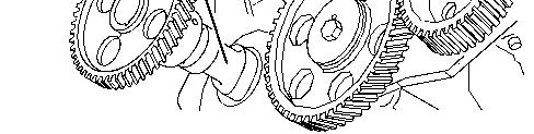
Illustration 2g01350309
https://127.0.0.1/sisweb/sisweb/techdoc/techdoc_print_page.jsp?returnurl=/sisweb/sisweb
This is the sample of the manual
Click on the download link for complete Manual
Typical example
NOTICE
Do not damage the lobes or the bearings when the camshaft is removed or installed.
Carefully remove camshaft assembly (4) from the cylinder block. 6. If necessary, remove the camshaft gear. Refer to Disassembly and Assembly, "Camshaft Gear.Remove and Install".
Installation Procedure
Table 1
Required Tools
9U-7324 Indicator Bracket 1
7H-1942 Dial Indicator 1
3S-3268 Indicator Contact Point 1
7H-1940 Universal Attachment 1
NOTICE
Keep all parts clean from contaminants.
Contaminants may cause rapid wear and shortened component life.
Ensure that the camshaft assembly is clean and free from wear or damage. If necessary, install the camshaft gear. Refer to Disassembly and Assembly, "Camshaft Gear.- Remove and Install". 1. Lubricate the camshaft assembly with clean engine oil prior to installation. 2.
https://127.0.0.1/sisweb/sisweb/techdoc/techdoc_print_page.jsp?returnurl=/sisweb/sisweb