

Product: MULTI TERRAIN LOADER
Model: 277C MULTI TERRAIN LOADER JWF
Configuration: 277C Multi Terrain Loader JWF00001-UP (MACHINE) POWERED BY 3044C Engine
Disassembly and Assembly
279C2 Compact Track Loader and 287C, 277C, 277C2 and 297C Multi Terrain Loaders Engine Supplement
Media Number -KENR5191-03
Publication Date -01/08/2011
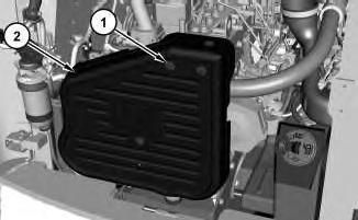
Air Cleaner - Remove and Install
SMCS - 1051-010
Removal Procedure
Date Updated -17/08/2011
i02667975
1. Tilt the radiator. Refer to Operation and Maintenance Manual, "Radiator Tilting".
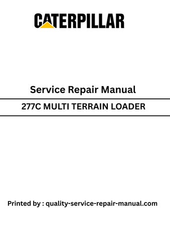
Illustration 1 g01340815
2. Disconnect harnessassembly (2). Disconnect hoses (1) and (5). Remove bolts(3) and air cleaner (4) .
Installation Procedure
1. Tilt the radiator. Refer to Operation and Maintenance Manual, "Radiator Tilting".
2. Position air cleaner (4) and install bolts (3). Connect hoses (1) and (5). Connect harness assembly (2) .
3. Tilt the radiator back to the original position. Refer to Operation and Maintenance Manual, "Radiator Tilting".
Copyright 1993 - 2020 Caterpillar Inc. All Rights Reserved. Private Network For SIS Licensees. Fri Jun 12 12:08:02 UTC+0530 2020
Product: MULTI TERRAIN LOADER
Model: 277C MULTI TERRAIN LOADER JWF
Configuration: 277C Multi Terrain Loader JWF00001-UP (MACHINE) POWERED BY 3044C Engine
Disassembly and Assembly
279C2 Compact Track Loader and 287C, 277C, 277C2 and 297C Multi Terrain Loaders Engine Supplement
Media Number -KENR5191-03
Publication Date -01/08/2011
Alternator - Remove and Install
SMCS - 1405-010
Removal Procedure
Start By:
Date Updated -17/08/2011
i03037501
A. Disconnect the battery. Refer to Disassembly and Assembly, "Battery and Battery CableSeparate and Connect".
Note: Put identification marks on all hoses, on all hose assemblies, on all wires, and on all tube assembliesfor installation purposes. Plug all hose assembliesand all tube assemblies. This helps to prevent fluid loss, and this helps to keep contaminants from entering the system.
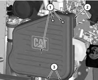
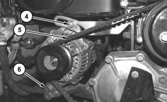
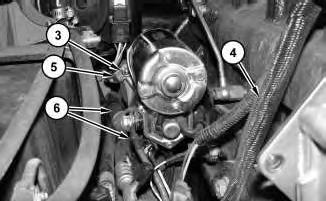
Illustration 1 g01367148
1. Remove screws (1) and loosen bolts (3) . Remove cover (2) .

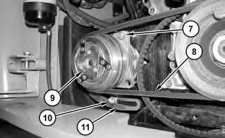
Illustration 2
g01367156
2. Remove bolts (4) and (6) . Remove belt (5) .
Illustration 3
g01336097
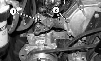
3. Position alternator (7) in order to accessharnessassembly (8) . Disconnect harness assembly (8) and remove alternator (7) .
Installation Procedure
4
5
1. Position alternator (7) in order to allowaccess to connect harness assembly (8) . Connect harnessassembly (8) .
2. Install alternator (7) . Install belt (5) . Install bolts (4) and (6) . Refer to Operation and Maintenance Manual, "Belt - Inspect/Adjust/Replace" for the proper belt tension.
3. Position cover (2) between the bracket assembly (9) and plate (10) . Apply Tooling (A) onto screws (1) and install screws(1) . Tighten screws(1) to a torque of 12 ± 3 N·m (9 ± 2 lb ft).
4. Apply Tooling (A) onto bolts (3) and install bolts (3) . Tighten bolts (3) to a torque of 15 ± 3 N·m (11 ± 2 lb ft).
End By: Connect the battery. Refer to Disassembly and Assembly, "Battery and Battery CableSeparate and Connect". Copyright 1993 - 2020 Caterpillar Inc.
Fri Jun 12 12:03:37 UTC+0530 2020
Product: MULTI TERRAIN LOADER
Model: 277C MULTI TERRAIN LOADER JWF
Configuration: 277C Multi Terrain Loader JWF00001-UP (MACHINE) POWERED BY 3044C Engine
Disassembly and Assembly
279C2 Compact Track Loader and 287C, 277C, 277C2 and 297C Multi Terrain Loaders Engine Supplement
Media Number -KENR5191-03
Publication Date -01/08/2011
Date Updated -17/08/2011
Battery and Battery Cable - Separate and Connect
SMCS - 1401-029-KA
Removal Procedure
Start By:
A. Tilt the cab. Refer to Disassembly and Assembly, "Cab - Tilt".
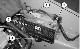
Illustration 1
1. Disconnect negative battery cable (2) .
2. Disconnect positive battery cable (1) .
g01321826
3. Remove bolt (4) and the clamp. Remove battery (3). The weight of the battery is approximately 18 kg (40 lb).
Installation Procedure
i02636401
This is the sample of the manual
Click on the download link for complete Manual
Illustration 2
1. Install battery (3). The weight of the battery is approximately 18 kg (40 lb). Position the clamp and install bolt (4) .
2. Connect positive battery cable (1) .
3. Connect negative battery cable (2) .
End By: Lower the cab. Refer to Disassembly and Assembly, "Cab - Tilt".
Copyright 1993 - 2020 Caterpillar Inc. All Rights Reserved. Private Network For SIS Licensees. Fri Jun 12 12:03:06 UTC+0530 2020
Product: MULTI TERRAIN LOADER
Model: 277C MULTI TERRAIN LOADER JWF
Configuration: 277C Multi Terrain Loader JWF00001-UP (MACHINE) POWERED BY 3044C Engine
Disassembly and Assembly
279C2 Compact Track Loader and 287C, 277C, 277C2 and 297C Multi Terrain Loaders Engine Supplement
Media Number -KENR5191-03 Publication Date -01/08/2011 Date Updated -17/08/2011
Cab - Tilt
SMCS - 7301-084
Raising the Cab
Do not go beneath cab unlesscabisempty and support lever is engaged.
Failure to follow the instructionsor heed the warnings could result in injury or death.
i02674905
Do not tilt the cab using an open door. The door must be closed and latched when lifting the cab. The door may become dislodged from its hinges and may cause serious personal injury or death.
1. Park the machine on level ground.
Note: Empty the water tank (if equipped) before you tilt the cab.
2. Lower the loader arms. If you tilt the cab upward with the loader lift arms in the RAISED position, you must engage the brace for the loader lift arms. See Operation and Maintenance Manual, "Loader Lift Arm Brace Operation" for the processfor engaging the brace for the loader lift arms.
3. Release the hydraulic system pressure. Refer to Disassembly and Assembly, "Hydraulic System Pressure - Release".
4. Close the cab door and ensure that the door islatched.
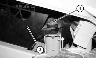
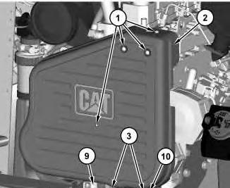
Illustration 1
5. Remove bolts (1) .
g01344027
Note: Note the location of the rubber mountsand the spacers for assembly purposes.
6. Raise cab (2) .
2 g01210136
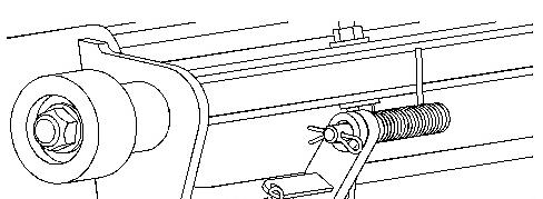
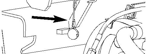
Illustration 3 g01210140
Cabsupportlever
7. Raise the cab until the cab support lever is in the ENGAGED position.
Lowering the Cab
Illustration 4 g01210140
Cabsupportlever
Copyright 1993 - 2020 Caterpillar Inc.
Rights Reserved.
Network For SIS Licensees. Fri Jun 12 12:09:07 UTC+0530 2020
Product: MULTI TERRAIN LOADER
Model: 277C MULTI TERRAIN LOADER JWF
Configuration: 277C Multi Terrain Loader JWF00001-UP (MACHINE) POWERED BY 3044C Engine
Disassembly and Assembly
279C2 Compact Track Loader and 287C, 277C, 277C2 and 297C
Multi Terrain Loaders Engine Supplement
Media Number -KENR5191-03
Publication Date -01/08/2011 Date Updated -17/08/2011
Electric Starting Motor - Remove and Install
SMCS - 1453-010
Removal Procedure
Start By:
i02659677
A. Remove the alternator. Refer to Disassembly and Assembly, "Alternator - Remove and Install".
Note: Put identification marks on all hoses, on all hose assemblies, on all wires, and on all tube assembliesfor installation purposes. Plug all hose assembliesand all tube assemblies. This helps to prevent fluid loss, and this helps to keep contaminants from entering the system.
NOTICE
Care must be taken to ensure that fluids are containedduring performance of inspection, maintenance, testing, adjusting and repair of the product. Be prepared to collect the fluid with suitable containers before opening any compartment or disassembling any component containing fluids.
Refer to Special Publication, NENG2500, "Caterpillar Dealer Service Tool Catalog" for tools and suppliessuitable to collect and contain fluids on Caterpillar products.
Dispose of all fluids according to local regulations and mandates.
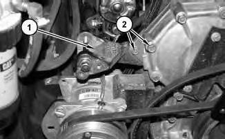
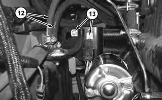
Illustration 1
g01339584
1. Remove bolts (2) and bracket assembly (1) .
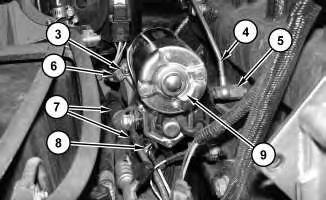
Illustration 2
g01340563
2. Disconnect harnessassembly (8) and cable assemblies (7) .
3. Disconnect tube assembly (4) and remove fitting (5).
Note: Fitting (5) must be removed in order to access the inside nut.
4. Remove nuts(3) and disconnect cable assembly (6). Remove electric starting motor (9) .
Installation Procedure
Note: Cleanliness is an important factor. Before assembly, thoroughly clean all partsin cleaning fluid. Allow the parts to air dry. Do not use wiping cloths or rags to dry parts. Lint may be deposited on the partswhich may cause trouble. Inspect all parts. If any parts are worn or damaged, use new parts for replacement. Dirt and other contaminants can damage the precision component. Perform assembly procedureson a clean work surface. Keep components covered and protected at all times.
2.
3.
Care must be taken to ensure that fluids are containedduring performance of inspection, maintenance, testing, adjusting and repair of the product. Be prepared to collect the fluid with suitable containers before opening any compartment or disassembling any component containing fluids.
Refer to Special Publication, NENG2500, "Caterpillar Dealer Service Tool Catalog" for tools and suppliessuitable to collect and contain fluids on Caterpillar products.
Dispose of all fluids according to local regulations and mandates.

4. Install bracket assembly (1) and bolts (2) .
End By: Install the alternator. Refer to Disassembly and Assembly, "Alternator - Remove and Install".
Copyright 1993 - 2020 Caterpillar Inc. All Rights Reserved. Private Network For SIS Licensees. Fri Jun 12 12:03:58 UTC+0530 2020
Product: MULTI TERRAIN LOADER
Model: 277C MULTI TERRAIN LOADER JWF
Configuration: 277C Multi Terrain Loader JWF00001-UP (MACHINE) POWERED BY 3044C Engine
Disassembly and Assembly
279C2 Compact Track Loader and 287C, 277C, 277C2 and 297C Multi Terrain Loaders Engine Supplement
Media
i04351954
Engine - Install
SMCS - 1000-012
Installation Procedure
Table 1 Required Tools
1
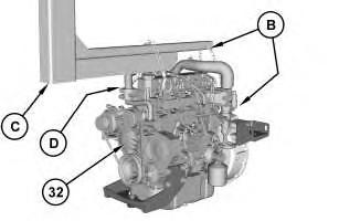
1. Attach Tooling (B) , Tooling (C) , Tooling (D) , and a suitable lifting device to engine (32) . The weight of engine (34) is approximately 340 kg (750 lb).
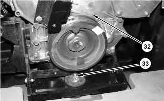
Illustration 2
2. Position engine (32) in the machine. Install bolt (33) . Tighten bolt (33) to a torque of 90 ± 10 N·m (66 ± 7 lb ft).
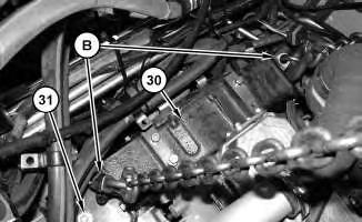
Illustration 3
3. Install nuts(31) . Remove Tooling (B) from housing (30) .
Note: Nylon rods are installed at the factory in order to support the bolts for nuts (31) during the installation process.
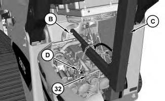
Illustration 4
TypicalExample of Tooling (C) .
4. Remove Tooling (B) , Tooling (C) , Tooling (D) , and the suitable lifting device from engine (32) .
5
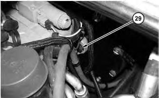
5. Install bolts (29) .
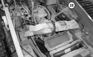
Illustration 6
7
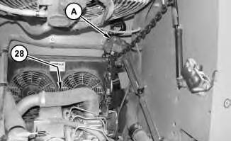
6. Remove the suitable cribbing and the suitable lifting device from pumps (28) . Remove Tooling (A) from pumps(28) .
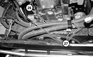
Illustration 8
7. Position hoses(26) . Install all clamps (27) that secure hoses (26) to the engine.
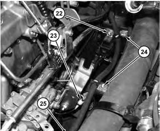
9
8. Connect hose (25) . Install bolts (22) and (24) .
9. Connect harness assembly (23) . Install all mounting hardware that retains harness assembly (23) to the engine.
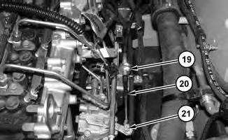
10
10. Connect cable assembly (20) and install pin assembly (21) . Tighten nut (19) .
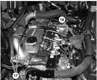
11
11. Install duct (16) . Connect hoses (17) and (18) .
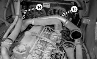
Illustration 12
12. Install tube assembly (15) and tighten hose clamp (14) .
13
13. Connect hoses (12) and install bolts (13) .
14
14. Position refrigerant compressor (9) . Install bracket (11) , bolts(10) , belt (8) , and nut (7) . Refer to Operation and Maintenance Manual, "Belts - Inspect/Replace"for the proper belt tension.
15
15. Connect cable assembly (5) and install nut (3) . Connect harness assembly (4) and cable assemblies(6) . Install all mounting hardware.
16
16. Install guard (2) and bolts(1) . End By:
a. Tilt the cab. Refer to Disassembly and Assembly, "Cab - Tilt".
b. Remove the muffler. Refer to Disassembly and Assembly, "Muffler - Remove and Install".
c. Install the air cleaner. Refer to Disassembly and Assembly, "Air Cleaner - Remove and Install".
This is the sample of the manual
Click on the download link for complete Manual
Product: MULTI TERRAIN LOADER
Model: 277C MULTI TERRAIN LOADER JWF
Configuration: 277C Multi Terrain Loader JWF00001-UP (MACHINE) POWERED BY 3044C Engine
Disassembly and Assembly
279C2 Compact Track Loader and 287C, 277C, 277C2 and 297C Multi Terrain Loaders Engine Supplement
Engine - Remove
SMCS - 1000-011
Removal Procedure
Table 1
Required Tools
Start By:
A. Remove the air cleaner. Refer to Disassembly and Assembly, "Air Cleaner - Remove and Install".
B. Remove the muffler. Refer to Disassembly and Assembly, "Muffler - Remove and Install".
C. Tilt the cab. Refer to Disassembly and Assembly, "Cab - Tilt".